Toggle Switch (PartTerminologyID 4780): Contact Configuration, Current Rating, and Panel Integration Compatibility
Written by Arthur Simitian | PartsAdvisory
Introduction
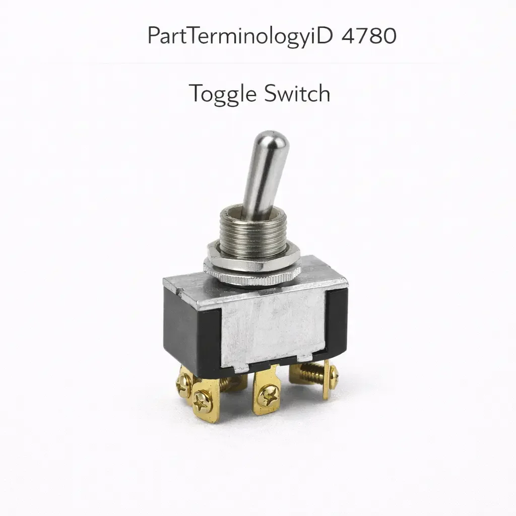
The toggle switch is a manually operated lever-actuated switch in which a projecting lever or bat handle is moved between two or more defined positions to open or close electrical circuits. In vehicle applications, toggle switches are used for accessory activation, lighting control, auxiliary equipment switching, and in commercial and off-road applications for controlling winches, light bars, compressors, and other aftermarket electrical systems. The toggle switch's distinctive lever handle provides tactile and visual confirmation of the switch state, making it intuitive in environments where gloves are worn or where the driver cannot look at the control panel.
Returns on PartTerminologyID 4780 come from a combination of incorrect contact configuration, inadequate current rating for the connected circuit, and incorrect panel mounting dimensions. These three attributes are straightforward to specify but are frequently omitted from listings, particularly for generic aftermarket toggle switches that are listed by panel cutout size without stating the contact configuration or current rating.
What the Toggle Switch Does
Circuit Control Through Lever Position
The toggle switch controls one or more electrical circuits by the position of its lever. In the most common two-position design, one lever position closes the circuit and the other opens it. The lever remains in the selected position until manually moved, making the toggle a latching switch by design. This is distinct from a push button switch, which is momentary by default unless specifically designed to latch.
On three-position designs the lever has a center position as well as two end positions. The center position may be the off state with both end positions being on states for different circuits, or the center may be one active state with the two end positions controlling different functions. On-off-on, on-off-momentary, and off-on-on are common three-position configurations used in vehicle accessory and auxiliary equipment applications.
Single Pole and Multi-Pole Designs
A single pole toggle switch controls one circuit path with one common terminal and one or two output terminals depending on the number of throw positions. A double pole toggle switch controls two independent circuit paths simultaneously with a single lever movement, providing two separate switched circuits that are mechanically linked but electrically isolated.
Double pole toggle switches are used when two circuits must be switched simultaneously, such as when both a positive and a negative circuit must be interrupted for safety or isolation purposes, or when two separate devices must be activated or deactivated together without allowing one to be on without the other.
Current Rating and Circuit Protection
The toggle switch is used across a wide range of current applications in vehicles, from low-current signal circuits carrying a few milliamperes to high-current accessory circuits carrying 20 or 30 amperes. The contact current rating of the switch must meet or exceed the maximum continuous current of the connected circuit. A switch with an undersized contact rating will overheat under sustained current, producing contact arcing, contact welding, and eventual switch failure or fire risk.
Contact current ratings for toggle switches are typically expressed as a maximum continuous current at a specified voltage. The rating at 12 VDC is the relevant specification for most vehicle applications. Some switches are rated at both AC and DC, and the DC rating is typically lower than the AC rating for the same switch because DC current does not cross zero during each cycle, which makes arc extinction more difficult.
Design and Construction
Lever and Actuator Designs
Toggle switch levers are available in several styles. The bat handle is the most common vehicle application design, a short cylindrical or rectangular lever that provides a secure grip with one finger. The paddle handle is a broader, flatter lever used on panel-mounted switches where precise lever position is less important than switch visibility and accessibility. The safety cover design adds a hinged clear or red cover that must be flipped open before the switch can be actuated, providing protection against accidental activation of circuits that control high-current loads or safety-critical systems.
Panel Mounting
Toggle switches mount in circular or rectangular panel cutouts. The body of the switch passes through the panel cutout and a mounting nut or snap-retention tabs hold the switch body to the panel from the back. The panel cutout diameter must match the switch body diameter exactly. An oversized cutout allows the switch to rattle and shift, affecting both appearance and contact durability. An undersized cutout prevents installation.
On vehicles with molded instrument panel inserts, the toggle switch mounting positions are designed for specific switch body diameters. Confirming the mounting hole diameter before ordering prevents returns from switches that do not fit the panel.
Sealing and Environmental Rating
Vehicle toggle switches in engine bay, cargo area, or exterior-accessible locations require environmental sealing to resist moisture, dust, and contamination. Sealed toggle switches include a rubber boot over the lever and a sealed body that prevents moisture intrusion through the panel cutout and the lever shaft. Unsealed switches used in exterior or exposed locations will develop contact corrosion from moisture exposure, producing intermittent contact and eventual switch failure.
Interior cabin toggle switches are typically unsealed because the cabin environment does not require the level of protection needed for exterior applications. Installing an unsealed switch in an exterior application is a common cause of premature toggle switch failure.
Common Failure Modes
Contact Wear from Overloading
The most common cause of toggle switch failure in vehicle applications is using a switch with a contact current rating that is too low for the connected load. A switch rated for 15 amperes installed in a winch circuit drawing 30 amperes under load will have its contacts arc on each switching event. Over a small number of switching cycles the contact surfaces become pitted and develop increased resistance, producing voltage drop that reduces the voltage available to the connected load. Eventually the contacts weld, either in the open state (load cannot be activated) or the closed state (load cannot be deactivated).
Lever Fatigue and Detent Wear
The lever pivot mechanism and the detent ball or spring that holds the lever in position can wear over time, allowing the lever to rest between defined positions or to shift under vibration. A lever that moves to an intermediate position opens or partially opens the contact set, producing an intermittent high-resistance connection. This failure mode is more common on switches in high-vibration environments such as off-road vehicles and commercial trucks.
Moisture Intrusion in Unseal Designs
An unsealed toggle switch in a wet or high-humidity environment will develop corrosion on the contact surfaces within the switch body. The corrosion increases contact resistance and eventually produces an open circuit. On switches used in marine or outdoor environments, the transition from occasional intermittent contact to complete failure can occur within a single season if the switch is not sealed.
Symptoms of a Failing Toggle Switch
Connected Load Does Not Operate in Either Lever Position
A complete failure to operate in either lever position points to an open circuit either in the switch contacts or in the wiring. Disconnect the switch connector and test continuity between the contact terminals in each lever position. A contact set that does not show continuity in either position confirms an open circuit in the switch. If both positions show continuity correctly, the fault is in the wiring or the connected load.
Load Operates Intermittently
Intermittent load operation that does not correlate consistently with lever position points to a high-resistance contact set or a loose lever mechanism. A contact with elevated resistance may produce enough voltage drop to prevent the connected load from operating correctly even though continuity is technically present. Measure voltage drop across the switch contacts while the load is operating to confirm contact resistance.
Load Cannot Be Deactivated
A load that continues to operate regardless of lever position points to a contact set that is welded closed. Disconnect the switch connector to confirm whether the load stops with the switch disconnected. If it does, the switch contacts are welded. If the load continues after switch disconnection, the circuit has a short that is keeping the load powered independently of the switch.
Cataloging Attributes: What to Confirm Before Listing
Contact configuration: State the configuration explicitly using standard terminology: SPST (single pole single throw), SPDT (single pole double throw), DPST (double pole single throw), or DPDT (double pole double throw). Add the position count and momentary designation if applicable: SPDT on-off-on, SPDT on-off-momentary, or similar. This is the most critical electrical attribute and must be present in every listing.
Contact current rating: State the maximum continuous current in amperes at 12 VDC. Do not state the AC rating as a substitute for the DC rating on vehicle application listings. The DC rating is the relevant specification.
Panel mounting hole diameter: State the body diameter for the panel cutout in millimeters or inches. This is the primary physical fitment attribute.
Environmental sealing: State whether the switch is sealed or unsealed. For sealed switches, state the IP rating if available. For unseal switches, explicitly note that they are intended for indoor or cabin use only.
Lever style: State the lever type: bat handle, paddle handle, or safety cover. On applications where a specific lever style is required by the original installation, the lever style must match.
Terminal type: State the terminal connection type: solder lug, screw terminal, or quick-connect blade terminal with the blade size.
Common Cataloging Mistakes
The most common mistake is listing toggle switches with only the panel mounting hole size and a current rating without stating the contact configuration. A buyer who needs an SPDT on-off-on switch for a three-position auxiliary light control cannot determine from a listing that states only the panel hole size and current rating whether the switch performs the correct function. Contact configuration must be stated.
The second mistake is listing the AC current rating rather than the DC rating for vehicle application switches. A switch listed as a 20-ampere switch using its AC rating may have a DC rating of only 10 or 12 amperes. In a 15-ampere vehicle circuit this would produce contact arcing and premature failure. The DC rating at 12 volts must be the stated rating for all vehicle application listings.
The third mistake is not stating the environmental sealing designation. A buyer replacing a sealed toggle switch in an engine bay application who receives an unsealed switch will have a switch that fails within one season from moisture exposure. The sealing specification must be stated and confirmed against the application requirement.
Status in New Databases
PIES/PCdb: PartTerminologyID 4780, Toggle Switch
PIES 8.0 / PCdb 2.0: No change in PartTerminologyID or terminology label
Summary
PartTerminologyID 4780, Toggle Switch, covers a broad range of lever-actuated electrical switches used across vehicle control panel, accessory, and auxiliary equipment applications. The contact configuration, DC current rating, panel mounting hole diameter, and environmental sealing designation are the four attributes that determine whether the replacement functions correctly in the specific application. A listing that states only the panel hole size generates returns from every buyer whose application requires a specific contact configuration or current rating that was not stated. Contact configuration and DC current rating must be present in every listing without exception.