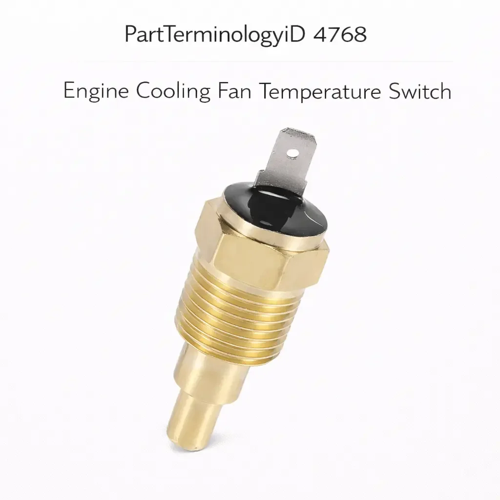
Engine Cooling Fan Temperature Switch (PartTerminologyID 4768): Activation Threshold, Fan Speed Stage, and System Integration
Written by Arthur Simitian | PartsAdvisory
Introduction
The engine cooling fan temperature switch is a thermostatic switch mounted in the engine coolant circuit that activates the electric cooling fan or fans when coolant temperature rises to a defined threshold. It is the primary control input for electric cooling fan activation on vehicles that do not use the ECM or a dedicated fan control module to manage fan operation. On vehicles with a two-speed or multi-speed fan system, multiple switches are used, each calibrated to a different temperature threshold corresponding to the appropriate fan speed stage.
The engine cooling fan temperature switch is a specific application of the broader coolant temperature switch category, and it shares PartTerminologyID space with the general coolant temperature switch under some catalog systems. What distinguishes the cooling fan temperature switch from other coolant temperature switches is its specific calibration for fan activation duty, its mounting location in a part of the coolant circuit that reflects system temperature accurately for fan control purposes, and in multi-stage systems, its designation as a low-speed, high-speed, or auxiliary fan switch with a threshold calibrated for each specific stage.
Returns on this PartTerminologyID are driven by the same omissions that affect the general coolant temperature switch category, with the additional complication that multi-stage fan systems require multiple switches at different thresholds and a listing that does not specify the fan speed stage as well as the threshold will generate returns from buyers who receive the wrong stage switch for their application.
The importance of correct fan switch calibration extends beyond simple cooling protection. Insufficient fan activation, caused by a switch with a threshold that is too high, allows coolant to reach higher temperatures during low-speed driving and idling than the engine management system expects. This affects the temperature at which the engine management system commands enrichment and timing retard, influences how quickly the catalytic converter reaches operating temperature after a cold start, and can cause the engine to operate in a thermal range where emissions are higher than designed. A correctly calibrated fan switch is not only a cooling protection component but a component that keeps the entire engine management and emissions system operating within its designed parameters.
This guide covers the complete picture for PartTerminologyID 4768: how the switch functions within the cooling fan circuit, how multi-stage fan systems are structured, how the switch fails, how to diagnose it accurately, and what catalog attributes must be present to prevent returns.
What the Engine Cooling Fan Temperature Switch Does
Single-Stage Fan Activation
On vehicles with a single-speed electric cooling fan, the cooling fan temperature switch provides the sole thermostatic control input for fan operation. When coolant temperature rises to the switch threshold, the switch closes its circuit and activates the fan relay, which supplies current to the fan motor. The fan runs at full speed until the coolant temperature drops below the switch's reset threshold, at which point the switch opens and the fan relay deactivates.
The single-stage design is common on older vehicles, smaller displacement engines, and vehicles where the cooling demand is modest enough that a single fan speed is adequate across all operating conditions. The threshold is typically calibrated to activate the fan slightly above the thermostat opening temperature, ensuring the fan assists cooling when the engine is at or near its normal operating temperature under low-speed or stationary conditions where ram air cooling through the radiator is minimal.
Two-Stage Fan Systems
On vehicles with a two-stage electric fan system, two separate coolant temperature switches control low-speed and high-speed fan operation at different temperature thresholds. The low-speed switch has a lower activation threshold, typically in the range of 85 to 95 degrees Celsius on most passenger car applications. It activates the fan at low speed when the engine is at normal operating temperature to provide continuous cooling during low-speed driving and extended idling.
The high-speed switch has a higher activation threshold, typically 100 to 110 degrees Celsius. It activates the fan at high speed when coolant temperature approaches the overtemperature range, such as during low-speed towing, extended idling in hot weather, or after a high-load highway run when the vehicle stops and loses ram air cooling.
The two switches must be correctly matched to their respective fan speed stages. A low-speed switch installed in the high-speed position will activate high-speed fan operation at normal operating temperature, creating unnecessary noise and electrical load. A high-speed switch installed in the low-speed position will delay low-speed fan activation until coolant temperature approaches the high-speed activation point, reducing cooling efficiency during normal operation.
Auxiliary Fan Control
On vehicles with a primary mechanical engine-driven fan and a secondary electric auxiliary fan, the cooling fan temperature switch controls only the auxiliary fan. The auxiliary fan activates when coolant temperature exceeds the switch threshold, supplementing the mechanical fan during low-speed operation when the mechanical fan's airflow is reduced. The auxiliary fan switch threshold is typically calibrated to activate the auxiliary fan before coolant temperature reaches the overtemperature warning threshold, providing a cooling buffer before the driver receives a warning.
Interaction with the AC System
On many vehicles the cooling fan circuit is shared between the cooling fan temperature switch and the AC pressure switch or AC system control. The fan activates when either the cooling fan temperature switch closes or the AC pressure switch closes. This ensures the fan runs whenever the AC compressor is operating, providing airflow through the condenser even when coolant temperature alone would not require fan activation.
A cooling fan temperature switch that fails open will not prevent the fan from running when the AC is active, because the AC pressure switch provides a parallel activation path. This means a failed cooling fan temperature switch may not produce obvious symptoms during AC operation but will produce overheating during slow-speed driving without AC, which is a specific and identifiable symptom pattern.
ECM Fan Control on Modern Vehicles
On modern vehicles the ECM manages cooling fan activation directly through the fan control module or the fan relay, using input from the coolant temperature sensor rather than from a discrete temperature switch. On these vehicles the cooling fan temperature switch may still be present as a backup protection circuit separate from the primary ECM-managed fan circuit, or it may have been eliminated entirely in favor of software-controlled fan management.
When the cooling fan temperature switch is a backup circuit on ECM-managed systems, the switch threshold is set above the normal ECM-commanded fan activation temperature. The switch activates the fan only if the primary ECM fan control has failed to activate it at the lower temperature, providing a last-resort protection against overheating from a primary fan control fault.
Design and Construction
Mounting Location
The cooling fan temperature switch is typically mounted in the lower radiator tank, the coolant outlet housing on the engine, the thermostat housing, or a dedicated boss in the engine block. The mounting location determines which portion of the coolant circuit the switch senses. Lower radiator tank mounting provides a good indication of the radiator's ability to cool the fluid before it returns to the engine. Engine outlet or thermostat housing mounting provides a better indication of the actual engine coolant temperature leaving the engine.
The lower radiator tank mounting location is particularly common on European and Asian platforms where the fan switch is designed to respond to the cooled coolant temperature returning from the radiator. If the coolant temperature at the lower radiator tank remains below the threshold, it indicates the radiator is dissipating heat adequately and the fan does not need to run. If the cooled coolant temperature is still above the threshold, the radiator is not keeping up with the heat rejection demand and fan assist is needed.
On two-stage systems the two switches may be mounted at the same location in different threaded fittings, or at different locations that reflect different aspects of the cooling system's thermal state. Confirming the correct mounting location for each switch in a two-stage system is as important as confirming the correct threshold. Installing a low-speed switch in the high-speed switch location and vice versa will produce the same symptom as installing switches with reversed thresholds.
Thread Specification
Thread specifications for cooling fan temperature switches follow the same variations as general coolant temperature switches: metric threads in various diameters and pitches, NPT threads in standard pipe sizes, and in some applications proprietary thread forms specific to the vehicle manufacturer. The thread must engage fully and seal correctly. Tapered thread designs seal on the thread engagement. Straight thread designs require a sealing washer.
Common thread specifications include M10 x 1.0, M12 x 1.5, M14 x 1.5, and various NPT sizes. Thread mismatches produce either a loose fit with coolant leakage or cross-threading that damages the fitting in the radiator tank or engine housing. Confirming the thread specification from the vehicle service manual or from the original switch is the most reliable pre-installation step.
Contact Configuration and Current Rating
Cooling fan temperature switches that control a fan relay directly carry only the relay coil current through their contacts, typically 0.2 to 0.5 amperes. Switches that control the fan motor directly, found on some older and simpler systems, must carry the full fan motor current, which can reach 10 to 20 amperes depending on the fan motor size.
The contact current rating must be adequate for the circuit position the switch occupies. A relay coil-rated switch installed directly in a fan motor circuit will arc and fail rapidly under motor current. Confirming whether the switch controls a relay or connects directly to the motor is an essential pre-ordering step, and the appropriate contact current rating must be stated in every listing.
Normally Open versus Normally Closed
Cooling fan temperature switches are predominantly normally open designs that close when temperature rises above the threshold and open when it drops below the reset threshold. This allows the fan to remain off during cold startup, which is desirable for warm-up efficiency and cabin heating response. A normally closed switch design in this application would run the fan continuously from cold start, which is not the intended behavior on most applications.
On systems that use the cooling fan for both engine cooling and condenser cooling with an AC-commanded activation path, some designs use a normally closed switch that opens the dedicated AC fan circuit above a high-pressure threshold. These are the exception rather than the rule and must be confirmed from the service documentation before a replacement is ordered.
Common Failure Modes
Open Circuit Failure
A switch that fails open will not activate the fan regardless of coolant temperature. On vehicles where the cooling fan temperature switch is the sole fan activation input and the AC is not in use, this failure will allow the engine to overheat during low-speed operation or extended idling without any fan assistance. The first symptom is often an overtemperature warning lamp during stop-and-go traffic in hot weather.
Closed Circuit Failure
A switch that fails closed will activate the fan continuously from cold start. The fan running continuously from startup is the primary symptom. This is less immediately hazardous than an open circuit failure but reduces fuel economy, increases electrical system load, and can reduce fan motor life from continuous operation.
Calibration Drift
A switch whose activation threshold has drifted to a higher temperature will activate the fan later than designed, reducing the cooling protection margin at the lower end of the temperature range. A switch whose threshold has drifted lower will activate the fan earlier than designed, increasing fan run time unnecessarily. Both directions of calibration drift reduce cooling system efficiency relative to the designed operating point.
Thread Degradation and Coolant Leakage
Repeated installation and removal cycles, cross-threading during previous service, or use of incorrect thread sealant can damage the thread engagement and produce coolant leakage at the switch base. Even a slow coolant leak at the fan switch location should be addressed promptly because coolant can contact electrical connections on the switch terminal and accelerate terminal corrosion.
Connector Terminal Corrosion
The switch terminal connector is exposed to the engine bay environment and is subject to corrosion from moisture and road contamination. Corroded terminals produce a high-resistance connection that prevents the switch from completing the fan relay circuit reliably. Intermittent fan activation that worsens in wet weather often points to connector corrosion rather than a switch contact fault.
Symptoms of a Failing Engine Cooling Fan Temperature Switch
Engine Overheats at Idle or Low Speed Without Warning in Normal Traffic
If the engine overheats during stop-and-go traffic or extended idling without the AC active, and the cooling fan is not running, the cooling fan temperature switch is the most probable cause. Confirm the fan does not run by observation or by checking fan relay activation. If the fan relay does not activate when coolant temperature is above the switch threshold, the switch circuit has failed open. This symptom is most common on hot summer days when ambient temperature is high and the engine's thermal load is at its peak. A switch that functioned marginally through mild weather may fail to provide adequate activation on the first genuinely hot day of the season.
Cooling Fan Runs Continuously from Cold Start
A fan that runs immediately from cold start and never stops points to a switch that has failed closed. Disconnect the switch connector and confirm whether the fan stops. If it does, the switch has failed in the closed state. If the fan continues to run after switch disconnection, the fan is being commanded from a different activation source such as the AC circuit or a fan module command rather than from the switch. On some platforms the ECM can command the fan independently of the temperature switch as part of its thermal management strategy, which may cause the fan to continue running after switch disconnection if the ECM is independently commanding the fan.
Engine Overheats Only During AC Operation
On systems with a shared AC and cooling fan circuit, if the cooling fan temperature switch has failed open but the AC pressure switch still provides an activation path, the fan will run during AC operation but not during non-AC operation. Overheating during slow-speed non-AC driving but not during AC-equipped driving is a specific symptom that points to the cooling fan temperature switch as the failed component. This symptom pattern is valuable because it narrows the diagnosis efficiently before any testing is performed.
Fan Activates Late Under Heavy Load
If the fan activates later than expected during heavy load conditions, such as during a hill climb or towing, and coolant temperature rises higher than normal before the fan begins operating, the switch threshold may have drifted to a higher activation point. Compare the actual coolant temperature at which the fan activates (observed through a scan tool) to the switch specification to confirm calibration drift. A switch with calibration drift toward a higher threshold provides reduced protection margin and should be replaced even if the cooling system has not yet reached overtemperature.
Diagnostic Process
Step One: Confirm Fan Activation by Observation
With the engine at operating temperature (above the switch activation threshold) and the AC off, confirm whether the cooling fan is running. If it is not running when coolant temperature is above the threshold, the fan circuit has a fault. Use a scan tool to confirm actual coolant temperature rather than relying on the temperature gauge, because gauge calibration may differ from actual temperature. A gauge that reads mid-scale may correspond to a coolant temperature that is above or below the fan switch threshold depending on the gauge sender calibration.
Step Two: Bridge the Switch Terminals
Disconnect the switch connector and bridge the two switch terminals with a jumper wire. If the fan activates with the terminals bridged, the switch has failed open and the circuit downstream of the switch (relay and fan motor) is functional. If the fan does not activate with the terminals bridged, the fault is in the relay, the fan motor, or the wiring between the switch and the relay coil. This is the fastest single test that separates a switch fault from a downstream circuit fault.
Step Three: Test Switch Continuity at Temperature
With the switch removed and placed in water heated to the specified activation temperature (confirmed with a thermometer), test continuity between the switch terminals. A normally open switch should show continuity at the activation temperature. Allow the water to cool to the reset temperature and confirm continuity opens at or below the reset threshold. This test confirms both the activation and reset calibration of the switch and can identify a switch with calibration drift before installation of a replacement.
Step Four: Inspect the Connector and Wiring
Disconnect the switch connector and inspect terminals for corrosion and loose retention. Corroded terminals are a common cause of intermittent fan activation that is misdiagnosed as a switch fault. Test the wiring from the switch signal terminal to the fan relay coil to confirm circuit continuity and low resistance. A high-resistance connection between the switch and the relay coil will reduce the voltage available to the coil, potentially preventing relay activation even when the switch is producing a clean contact closure.
Step Five: Confirm Threshold on Multi-Stage Systems
On two-stage fan systems, confirm which switch position is being tested (low-speed or high-speed) and compare the switch threshold to the specification for that stage. Use a scan tool to monitor coolant temperature while bridging each switch position individually to confirm which stage is failing. Bridging only the low-speed switch position should activate low-speed fan operation. Bridging only the high-speed switch position should activate high-speed fan operation. If either stage does not respond to bridging, the fault is in the relay or motor for that stage rather than in the switch.
Cataloging Attributes: What to Confirm Before Listing
Activation temperature threshold: State the activation temperature in degrees Celsius. This is the most critical attribute. On multi-stage fan systems, state the threshold for each stage separately and designate which stage each threshold corresponds to.
Fan speed stage designation: State explicitly whether the switch is for low-speed fan activation, high-speed fan activation, or a single-speed system. This designation is required in addition to the threshold value because the threshold alone does not prevent the wrong stage switch from being ordered on platforms where both stages have a similar external appearance.
Reset temperature: State the reset temperature in degrees Celsius. The hysteresis between activation and reset determines how long the fan runs after the temperature drops below the activation threshold. This affects cooling system efficiency and fan run time after the heat source is removed.
Circuit output type: State normally open or normally closed. Cooling fan temperature switches are nearly always normally open, but this must be confirmed and stated rather than assumed.
Thread specification and sealing method: State the thread diameter, pitch, and thread form. State whether the switch uses tapered thread sealing or a sealing washer, and whether the sealing washer is included.
Contact current rating: State the relay coil current rating or the direct motor current rating as applicable. Confirm whether the switch controls a relay or the motor directly.
Mounting location: For multi-stage systems, state the intended mounting location (lower radiator tank, thermostat housing, engine block boss) as well as the stage and threshold. On platforms where both stage switches mount in the same location in adjacent fittings, the mounting location alone does not distinguish them, but it is still necessary to confirm correct installation positioning.
Common Cataloging Mistakes
The most common mistake on multi-stage fan systems is listing switches without the fan speed stage designation. Two switches for the same vehicle platform with different thresholds appear nearly identical in a catalog listing that shows only vehicle fitment and a generic description. Without the stage designation and threshold value, the buyer has no way to confirm which switch corresponds to their specific complaint: a fan that does not activate at low speed or a fan that activates at low speed but not high speed.
The second mistake is omitting the reset temperature. On vehicles where the cooling fan runs excessively after a normal driving cycle has ended, a switch with a reset temperature that is too close to the activation temperature may be cycling rapidly or may be failing to reset promptly after the heat source is removed. The reset temperature is a necessary specification for confirming hysteresis compatibility.
The third mistake is not confirming whether the switch controls a relay or connects directly to the fan motor. On older platforms where direct motor connection was common, a relay-coil-rated switch installed in a direct motor circuit will arc under motor current. The circuit position must be confirmed and the appropriate contact current rating must be stated for each listing.
The fourth mistake is conflating the cooling fan temperature switch with the general coolant temperature switch or the overtemperature warning switch. All three are coolant temperature switches in the broad sense, but they are calibrated for different thresholds and connected to different circuits. A cooling fan activation switch installed in an overtemperature warning lamp circuit will illuminate the warning lamp at normal operating temperature. An overtemperature warning switch installed in a fan activation circuit will not activate the fan until coolant temperature is dangerously high.
Related Components and Systems
Electric Cooling Fan Motor
The fan motor is the component the switch ultimately activates through the relay circuit. A fan motor that runs correctly when battery voltage is applied directly but does not run when the temperature switch activates the relay has a relay fault or a wiring fault between the relay contacts and the motor. Confirming motor operation by direct power application is the step that isolates switch and relay faults from motor faults.
Cooling Fan Relay
The fan relay is the intermediate component between the temperature switch and the fan motor on most applications. The relay coil receives the activation signal from the temperature switch, and the relay contacts supply battery current to the fan motor. A failed relay coil will not respond to the switch signal, and failed relay contacts will not supply current to the motor even when the coil is energized. Relay testing is the step between confirming the switch is activating its output and confirming the motor is receiving power.
Radiator and Coolant System Health
The cooling fan temperature switch provides thermal protection only within the limits of the cooling system's physical capacity. A cooling system with a marginal radiator, a restricted water pump, a failing thermostat, or low coolant level will allow coolant temperature to rise faster than the fan can manage. In these conditions the fan may run continuously and the overtemperature warning may still activate. Before attributing persistent overheating to a switch fault, confirm the cooling system's physical condition including radiator cleanliness, coolant level and condition, thermostat function, and water pump output.
AC Condenser Fan
On vehicles where a single fan serves both the radiator and the AC condenser, the cooling fan temperature switch and the AC pressure switch share control of the same fan relay or fan motor. Understanding this shared control architecture is important for diagnosing fan faults that appear only during AC operation or only during non-AC operation, as the symptom pattern reveals which activation path has failed.
Frequently Asked Questions
My cooling fan runs all the time even when the engine is cold. What is causing this?
A cooling fan that runs from cold start and never stops is most likely caused by a temperature switch that has failed in the closed position, or by a fan relay that is stuck in the activated state, or by the AC system commanding the fan through a separate activation path. Disconnect the temperature switch connector and observe whether the fan stops. If it does, the switch has failed closed. If it continues to run, the AC system or another command source is keeping the relay activated.
Can a failed cooling fan temperature switch cause the AC to stop working?
Not directly, unless the AC system's condenser cooling relies entirely on the electric cooling fan and the fan is not running because the switch has failed open. Without adequate airflow through the condenser, refrigerant head pressure rises until the AC high-pressure switch cuts off the compressor, which stops AC cooling. This is an indirect relationship rather than a direct electrical connection, and the root cause is the failed temperature switch preventing fan operation rather than the switch directly affecting the AC circuit.
How do I know which switch to replace on a two-speed fan system?
Identify which fan speed is not working. If the fan does not activate at all during normal driving without AC, the low-speed switch has failed. If the fan activates at low speed during normal driving but does not shift to high speed when the engine is under load in hot weather, the high-speed switch has failed. Confirm by monitoring coolant temperature with a scan tool while observing fan behavior, and by bridging each switch position individually to confirm which position is not activating the fan.
Is it safe to drive with a failed cooling fan temperature switch?
Driving with a failed open cooling fan temperature switch is safe on highways where ram air cooling maintains adequate coolant temperature without fan assistance. In stop-and-go traffic or extended idling in hot weather, a failed open switch removes the fan's contribution to cooling and can allow coolant temperature to rise to the overtemperature warning level. Repair should be completed before extended urban driving in hot conditions.
Status in New Databases
PIES/PCdb: PartTerminologyID 4768, Engine Cooling Fan Temperature Switch
PIES 8.0 / PCdb 2.0: No change in PartTerminologyID or terminology label
Summary
The engine cooling fan temperature switch is a thermostatic control component that activates the electric cooling fan at a defined coolant temperature threshold to maintain engine thermal management under low-speed and stationary operating conditions. On multi-stage fan systems multiple switches with different thresholds control different fan speed stages, and correct listing requires stating both the threshold and the stage designation for each switch. A switch with the wrong threshold, the wrong stage designation, or the wrong contact current rating for its circuit position will either fail to provide adequate cooling or will activate the wrong fan speed at the wrong temperature.
Catalog listings for PartTerminologyID 4768 must state the activation temperature threshold, the fan speed stage designation for multi-stage applications, the reset temperature, the circuit output type, the thread specification, and the contact current rating. The combination of threshold and stage designation is what distinguishes individual switches in a multi-stage system from each other, and the absence of either attribute from a listing makes correct selection impossible when more than one variant covers the same vehicle application.