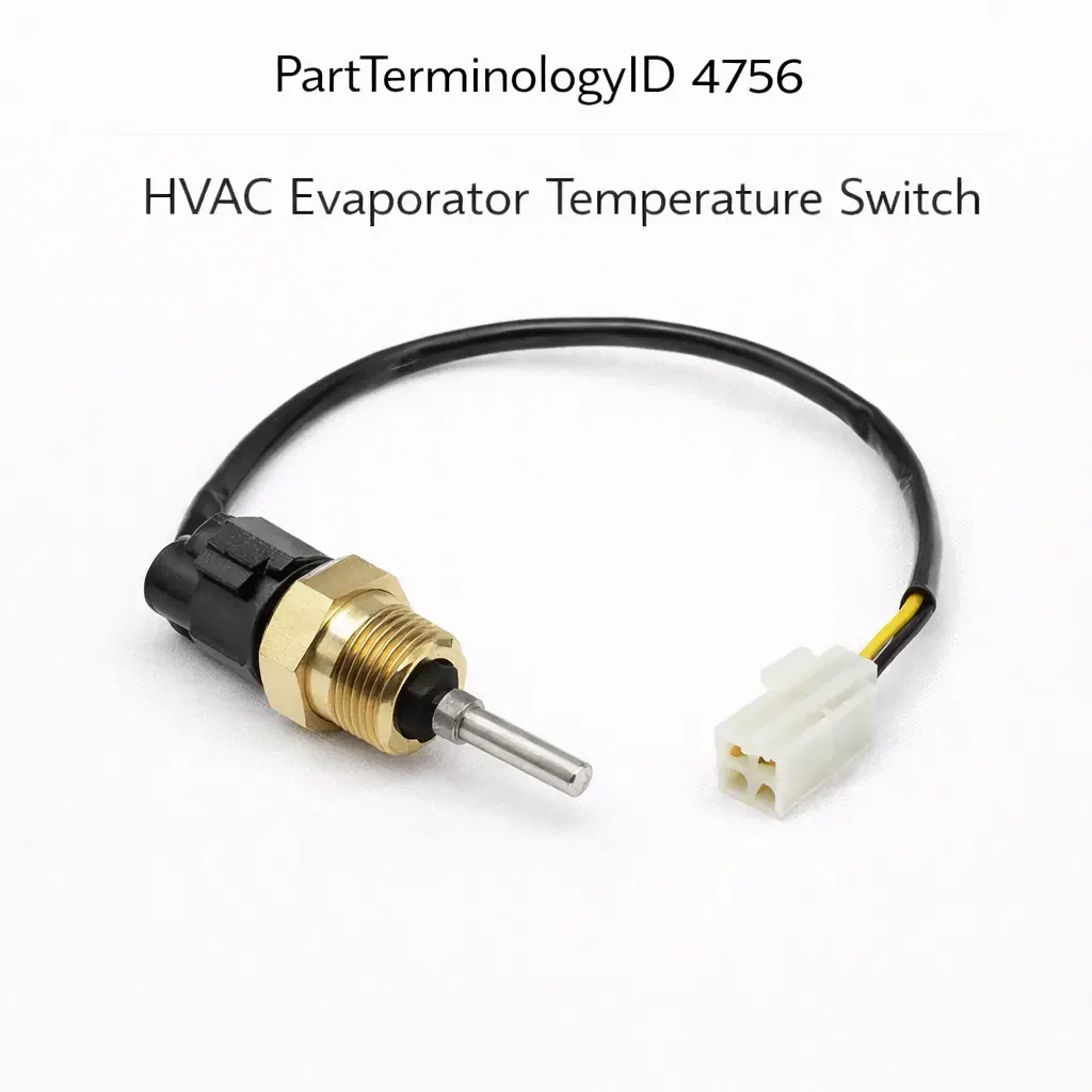
HVAC Evaporator Temperature Switch (PartTerminologyID 4756): Activation Threshold, Circuit Output Type, and Freeze Protection Calibration
Written by Arthur Simitian | PartsAdvisory
Introduction
The HVAC evaporator temperature switch is a thermostatic switch that monitors the surface temperature of the evaporator core in the vehicle's air conditioning system and cycles the compressor clutch off when evaporator temperature drops to the threshold at which ice formation would begin. Without this protection, moisture condensed on the evaporator fins would freeze, progressively reducing airflow through the core until the AC system delivers little or no cold air. The switch prevents this condition by interrupting compressor operation before the evaporator reaches the freezing point, allowing any accumulated condensate to drain before the cycle resumes.
The evaporator temperature switch is sometimes confused with the HVAC pressure in-cycle switch (PartTerminologyID 4636), which performs a similar compressor cycling function but monitors refrigerant pressure rather than evaporator surface temperature. Both components protect the AC system and cycle the compressor, but through different sensing mechanisms, at different points in the system, and with different calibration attributes. Confusing the two generates returns and leaves the underlying system protection issue unresolved. This guide covers the evaporator temperature switch specifically, with explicit distinction from the pressure switch where overlap might cause confusion.
What the HVAC Evaporator Temperature Switch Does
Evaporator Freeze Protection
The evaporator core operates at a surface temperature below the dew point of the cabin air passing through it, which causes moisture to condense on the fins. This is normal and desirable because it dehumidifies the cabin air. The condensate drains from the evaporator housing through a drain tube to the outside of the vehicle. The problem begins when the evaporator surface drops below 0 degrees Celsius: the condensate freezes on the fins instead of draining, and the ice layer progressively blocks airflow through the core.
The evaporator temperature switch prevents this by monitoring the evaporator surface temperature and opening the compressor clutch circuit when temperature reaches the activation threshold, typically set between 0 and 4 degrees Celsius depending on the application. With the compressor off, the refrigerant flow through the evaporator stops, the evaporator temperature rises as the cabin air continues to warm it, and any ice that has begun to form melts and drains. When the evaporator temperature rises above the switch's upper threshold (the reset threshold), the switch closes the compressor clutch circuit and cooling resumes.
Compressor Clutch Circuit Control
The evaporator temperature switch is wired in series with the compressor clutch circuit, similar to the pressure in-cycle switch. When the switch opens, the clutch circuit is broken and the compressor disengages. When the switch closes, the clutch circuit is completed (subject to other switches in the circuit also being closed) and the compressor can engage.
On systems where the compressor clutch circuit passes through multiple protective switches in series, all switches must be in the closed state simultaneously for the compressor to run. The evaporator temperature switch is one of these series switches. A switch that fails open will prevent the compressor from running at all, producing no cooling. A switch that fails closed removes the freeze protection function, allowing the evaporator to ice over.
Integration with the AC Control Module
On modern vehicles with a dedicated AC control module or HVAC control module, the evaporator temperature switch may be an input to the module rather than a direct switch in the clutch circuit. The module reads the switch state and commands the compressor clutch through its own output driver based on the switch input combined with other inputs including refrigerant pressure, cabin temperature, and compressor speed. On these systems the switch signal format must be compatible with the module input circuit.
Distinguishing the Evaporator Temperature Switch from the Pressure In-Cycle Switch
Both the evaporator temperature switch and the HVAC pressure in-cycle switch cycle the compressor to protect the AC system, and both are wired in or near the compressor clutch circuit. The distinction is in what they sense and at what point in the AC system they are installed.
The pressure in-cycle switch is mounted in the refrigerant circuit, typically on the high-pressure side or in a service port fitting. It monitors refrigerant pressure, not temperature. Its activation thresholds are expressed in psi or bar. It protects against both high-pressure overloads and low-pressure conditions caused by low refrigerant charge.
The evaporator temperature switch is mounted on or near the evaporator core inside the HVAC housing, typically through a probe that extends into the fins or a sensor clip that contacts the fin surface. It monitors evaporator surface temperature, not refrigerant pressure. Its activation threshold is expressed in degrees Celsius. It protects specifically against evaporator icing.
A pressure in-cycle switch cannot replace an evaporator temperature switch and vice versa. They sense different parameters, mount in different locations, and produce their protective action at different points in the operating cycle.
Design and Construction
Probe-Type Mounting
The most common evaporator temperature switch design uses a sensing probe that extends through the HVAC housing wall into contact with the evaporator fins. The probe contains the thermostatic sensing element and is positioned to contact the coldest area of the evaporator surface, which is typically near the refrigerant inlet where the refrigerant is coldest after expanding through the expansion valve.
The probe length and the HVAC housing penetration point are specific to the vehicle and must match exactly. A probe that is too short will not reach the evaporator fins and will sense housing air temperature rather than fin temperature, producing inaccurate activation timing. A probe that is too long may contact internal components of the HVAC housing and cause damage or produce a reading affected by the housing structure rather than the fin surface.
Clip-Type Mounting
Some evaporator temperature switches use a clip-type design that attaches to the evaporator fins directly rather than through a housing penetration. The clip holds the sensing element in contact with a specific fin location. Clip-type switches are typically found on applications where the HVAC housing does not have a dedicated switch port and the switch is accessed during evaporator service rather than from the engine bay.
Thermistor versus Bimetallic Sensing Elements
Evaporator temperature switches use either a bimetallic element or a thermistor as the temperature sensing mechanism. Bimetallic designs use a bimetallic disc that snaps between two states at the activation temperature, producing a definitive on-off contact change. Thermistor designs use a thermistor whose resistance change is interpreted by an AC control module to determine when to cycle the compressor. Bimetallic designs are standalone switches with a direct contact output. Thermistor designs require the AC module to process the signal and are not interchangeable with bimetallic switch designs even if both are calibrated to the same temperature threshold.
Common Failure Modes
Calibration Drift
The bimetallic element in a snap-action switch can lose its calibration over time from thermal fatigue, causing it to activate at a different temperature than its design threshold. A switch that activates at a temperature above its calibrated threshold will allow the evaporator to ice over before the compressor cycles off, resulting in reduced airflow and cooling. A switch that activates below its calibrated threshold will cycle the compressor off prematurely, reducing cooling capacity in conditions where the evaporator would not actually ice over.
Probe Seal Failure
On probe-type switches the seal between the probe and the HVAC housing must remain intact to prevent recirculated cabin air from bypassing the evaporator and to prevent condensate from reaching the switch body and electrical connections. A failed probe seal produces a reduction in AC efficiency as unconditioned air bypasses the evaporator, and can allow moisture to enter the switch housing and corrode the contacts.
Contact Failure from Moisture Exposure
Evaporator temperature switches are installed in a humid environment inside the HVAC housing where condensate is continuously present. Even with a sealed switch body, moisture can reach the electrical contacts over time through the connector seal or housing seal, causing contact corrosion and intermittent or absent switch function.
Thermistor Element Failure on Module-Controlled Systems
On systems where the switch contains a thermistor rather than a bimetallic contact, the thermistor can fail open or short, producing the same symptoms as a failed compressor clutch switch (no cooling) or no symptoms (no freeze protection). Module fault codes referencing the evaporator temperature input circuit are the most reliable indicator of thermistor element failure on these systems.
Symptoms of a Failing Evaporator Temperature Switch
AC System Does Not Cool, Compressor Does Not Run
A switch that has failed open will prevent the compressor from engaging regardless of system pressure or cabin temperature. Before replacing the switch on a no-cooling complaint, bridge the switch terminals to confirm the compressor engages. If it does, the switch has failed open. If the compressor still does not engage with the switch bridged, the fault is in another series switch or the clutch circuit.
AC Blows Warm After Running Normally, Then Cools Again After a Pause
This intermittent warm air pattern is the classic symptom of evaporator icing. The AC cools normally until ice blocks airflow, then delivers warm air until the ice melts. The switch is not providing freeze protection by cycling the compressor off before icing occurs. This indicates a switch that has failed in the closed position, has a calibration threshold that is too low, or is not correctly positioned to sense evaporator fin temperature.
AC System Cools But Cycles Frequently
If the compressor cycles on and off more frequently than expected under moderate temperature conditions, the switch activation threshold may have drifted to a higher temperature than calibrated, causing it to cycle the compressor off before the evaporator has reached maximum cooling capacity. This can also indicate a partially blocked evaporator drain that keeps the evaporator colder than normal, but switch calibration drift is the more common cause.
Diagnostic Process
Step One: Confirm Compressor Clutch Engagement
Visually confirm whether the compressor clutch is engaging when the AC is switched on. If the clutch does not engage, bridge the evaporator temperature switch terminals to confirm whether the switch is preventing engagement. If the clutch engages with the terminals bridged, the switch has failed open.
Step Two: Measure Switch Resistance or Continuity at Temperature
Remove the switch and place the sensing probe in ice water (approximately 0 degrees Celsius). A correctly functioning switch should open its contacts at or below this temperature. Then allow the probe to warm to room temperature. The switch should close its contacts as the temperature rises above the reset threshold. A switch that does not change state at the expected temperatures has failed or drifted.
Step Three: Check Probe Positioning
Confirm the switch probe is correctly positioned to contact the evaporator fins. A probe that is not reaching the fins will not sense evaporator temperature accurately. Confirm the probe length specification for the application before installing the replacement.
Step Four: Inspect the Evaporator Drain
If the AC ices over despite a correctly functioning switch, inspect the evaporator drain tube for blockage. A blocked drain retains condensate on the evaporator, increasing the rate of ice formation and the thermal load the switch must respond to. Clear any drain blockage before completing the diagnosis.
Step Five: Retrieve AC Module Fault Codes
On module-controlled systems, retrieve DTCs from the AC or HVAC control module. Codes referencing the evaporator temperature input confirm the switch circuit as the fault area and indicate the specific fault type.
Cataloging Attributes: What to Confirm Before Listing
Activation temperature threshold: State the compressor-off activation temperature and the reset temperature in degrees Celsius. Both values must be stated. A listing with only the activation threshold does not allow the buyer to confirm the hysteresis range between the off and on temperatures.
Circuit output type: State whether the switch produces a direct contact output (normally open or normally closed) or a thermistor resistance output for an AC control module input. These two output types are not interchangeable.
Probe length and mounting type: State the probe length and the mounting type (probe through housing wall, clip on fins, or other). An incorrect probe length will prevent correct evaporator temperature sensing regardless of calibration accuracy.
Connector pin count and body type: State the pin count. Evaporator temperature switches range from two-pin on direct contact designs to three-pin on designs with a separate signal and ground.
Distinction from pressure in-cycle switch: Every listing must clearly state that this is an evaporator temperature switch, not an AC pressure switch. Both components perform compressor cycling functions and both are sold as AC system switches. The distinction must be explicit.
Common Cataloging Mistakes
The most common mistake is omitting the activation temperature threshold. On platforms where multiple evaporator temperature switch variants were used with different thresholds, a listing without the threshold value forces the buyer to guess, and the wrong threshold produces either evaporator icing (threshold too high) or reduced cooling capacity (threshold too low).
The second mistake is not distinguishing the evaporator temperature switch from the pressure in-cycle switch. Both cycle the compressor, both are part of the compressor clutch circuit, and both are sometimes generically described as AC switches. A buyer who needs the evaporator temperature switch and receives a pressure in-cycle switch cannot install it in the HVAC housing because it has no temperature sensing probe, and the reverse creates a safety risk by removing pressure-based compressor protection.
The third mistake is not stating the probe length. On platforms where multiple evaporator housing designs were used across model years with different probe port depths, a switch with the correct calibration but incorrect probe length will not sense evaporator temperature correctly and will not provide effective freeze protection.
Related Components and Systems
AC Compressor Clutch
The AC compressor clutch is the electromagnetic coupling that connects and disconnects the compressor from the drive belt. The evaporator temperature switch controls this clutch through its series position in the clutch circuit. A clutch that does not disengage when the switch opens indicates that the switch output is not correctly wired in series with the clutch circuit, or that the switch output is being bypassed by a parallel path in the circuit. Confirm the switch is correctly wired before diagnosing a clutch that runs continuously.
AC Compressor Clutch Relay
On systems where the clutch circuit passes through a relay, the evaporator temperature switch activates the relay coil rather than directly switching the clutch current. The relay contacts carry the clutch current. A failed relay will prevent the clutch from engaging regardless of switch state. Confirming relay function by substituting a known-good relay is the fastest way to eliminate the relay as a fault source before testing the switch.
Expansion Valve or Orifice Tube
The expansion valve or orifice tube controls refrigerant flow into the evaporator and determines the evaporator operating temperature range. A stuck-open expansion valve allows excessive refrigerant flow, causing the evaporator to operate at a lower than normal temperature and triggering the evaporator temperature switch more frequently than expected. A stuck-closed valve reduces refrigerant flow, causing the evaporator to operate warmer than normal and potentially preventing the switch from activating at all. If the switch appears to be activating at the wrong temperature, the expansion valve condition should be evaluated before condemning the switch.
HVAC Evaporator Drain
The evaporator drain tube routes condensate from the HVAC housing to the exterior of the vehicle. A blocked drain retains condensate in the housing, increasing the volume of moisture available to freeze on the evaporator fins and reducing the effectiveness of the temperature switch as freeze protection. If an evaporator icing complaint recurs after a correct switch replacement, inspect and clear the drain tube before further diagnosis.
Frequently Asked Questions
My AC works fine in the morning but stops cooling on hot afternoons. Is this the evaporator temperature switch?
An AC system that cools correctly in the morning but delivers warm air during the hottest part of the day is more likely to have a refrigerant charge issue or a condenser airflow problem than an evaporator temperature switch fault. High ambient temperatures increase the head pressure of the AC system, and a marginally low refrigerant charge that is adequate in the morning may produce high-pressure cutout events during peak afternoon heat. Before replacing the evaporator temperature switch on this complaint, have the refrigerant charge and condenser fan operation confirmed.
Can I bypass the evaporator temperature switch to restore AC function temporarily?
Bridging the switch terminals will restore compressor operation if the switch has failed open, but it removes evaporator freeze protection. In moderate humidity conditions the evaporator may not ice over during a short-term bypass, but in high humidity conditions icing can begin within minutes. A bypass should be used only as a diagnostic step to confirm the switch is the fault, not as a repair strategy. Replace the switch before returning the vehicle to normal use.
Does the evaporator temperature switch affect cabin humidity?
Indirectly, yes. The dehumidification function of the AC system depends on the evaporator operating cold enough to condense moisture from the cabin air. A switch that cycles the compressor off too early reduces the time the evaporator is cold enough to condense moisture effectively, leaving more humidity in the cabin air. A switch that fails closed and allows evaporator icing removes airflow through the core entirely, stopping dehumidification along with cooling. Correct switch calibration is necessary for both effective cooling and effective dehumidification.
Status in New Databases
PIES/PCdb: PartTerminologyID 4756, HVAC Evaporator Temperature Switch
PIES 8.0 / PCdb 2.0: No change in PartTerminologyID or terminology label
Summary
The HVAC evaporator temperature switch is a freeze protection device that cycles the AC compressor off when evaporator surface temperature drops to the icing threshold. It is distinct from the HVAC pressure in-cycle switch, which performs a similar compressor cycling function through refrigerant pressure monitoring rather than temperature sensing. Confusing the two generates returns and leaves the correct protective function unrestored.
Every listing for PartTerminologyID 4756 must state both the activation and reset temperature thresholds, the circuit output type, the probe length and mounting type, and the connector pin count. The activation threshold is the most consequential attribute because an incorrect threshold directly determines whether the system provides effective freeze protection or cycles prematurely. The probe length is the installation compatibility attribute that ensures the sensing element actually contacts the evaporator fin surface at the correct depth for accurate temperature measurement.