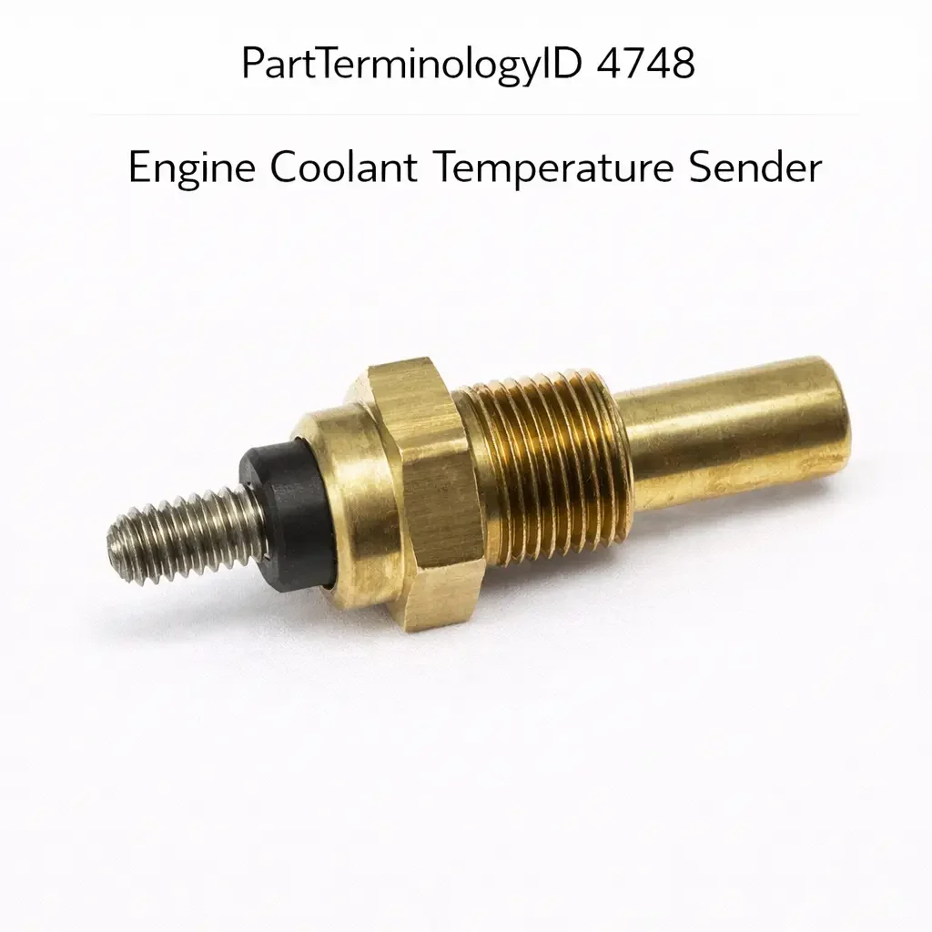
Engine Coolant Temperature Sender (PartTerminologyID 4748): Resistance Curve, Gauge Compatibility, and Sender versus Sensor Distinction
Written by Arthur Simitian | PartsAdvisory
Introduction
The engine coolant temperature sender is a variable-resistance thermistor mounted in the engine coolant circuit that produces a continuously changing resistance output as coolant temperature changes. Its output drives the coolant temperature gauge in the instrument cluster, providing the driver with a visual indication of engine thermal status across the full operating temperature range. On some applications a single sender unit serves both the temperature gauge and the ECM coolant temperature input. On others the gauge sender and the ECM sensor are separate components installed in different coolant passage locations.
The engine coolant temperature sender is one of the three related but distinct coolant temperature components cataloged in the switches and sensors category, and confusing it with the other two is the primary source of returns on this PartTerminologyID. The coolant temperature switch (PartTerminologyID 4740) is a binary threshold device that activates warning systems and fan relays. The coolant temperature sensor (typically cataloged under sensors) provides the ECM with a precision signal for fuel and ignition management. The coolant temperature sender (PartTerminologyID 4748) drives the instrument cluster gauge. Each of these three components performs a different function, connects to a different circuit, and is calibrated to a different specification. A listing that does not make this distinction clearly will route the wrong component to a buyer who needed one of the other two.
Understanding this distinction, and understanding what attributes of the sender specifically must be confirmed before a replacement is ordered, is the foundation for correct parts selection on this PartTerminologyID. This three-way confusion between sender, sensor, and switch is more persistent in the aftermarket than might be expected because all three components are thermistors or thermostatic devices mounted in coolant passages with similar thread specifications. On many engines they are installed within inches of each other, and a technician unfamiliar with the specific platform may order a replacement based on physical description rather than circuit identification, and install a component that fits but does not perform the intended function. This guide covers everything needed to select, catalog, and install the correct engine coolant temperature sender for any application.
What the Engine Coolant Temperature Sender Does
Gauge Circuit Signal Generation
The coolant temperature sender's output is a variable resistance that changes as a function of coolant temperature. As coolant temperature increases, the sender's resistance decreases in a non-linear curve. As temperature decreases, resistance increases. The instrument cluster gauge or its driving circuit applies a reference voltage through the sender and reads the voltage drop produced by the sender's resistance. The gauge circuit converts this voltage into a mechanical deflection of the gauge needle, displaying the engine temperature to the driver.
The resistance-temperature curve of the sender is matched to the calibration of the specific instrument cluster gauge or gauge driving circuit. A sender with a different resistance curve will cause the gauge to read incorrectly across all or part of the temperature range. The gauge may read low when the engine is at normal operating temperature, high during cold startup, or both at the same time if the curve shape differs from the original rather than just being offset. A gauge that reads incorrectly provides the driver with misleading information about the engine's thermal state, which can lead to either unnecessary concern or failure to notice genuine overheating.
Gauge Full-Scale and Midpoint Calibration
The sender's resistance at two specific temperatures is the most important calibration data: the resistance at the gauge midpoint temperature, which corresponds to the normal operating temperature where the needle should rest during steady-state driving, and the resistance at the full-scale or overtemperature position, which corresponds to the temperature at which the gauge should read at or near the top of its arc.
On most passenger vehicle applications, the normal operating temperature corresponds to a coolant temperature between 85 and 100 degrees Celsius. The gauge should display mid-scale at this temperature. If the replacement sender's resistance at this temperature differs from the original's resistance, the gauge will read off-center during normal operation, which some drivers notice and report as a gauge fault even when the engine temperature is correct.
Dual-Function Sender Applications
On older vehicles and some current applications, a single sender provides both the gauge circuit signal and the ECM coolant temperature input on a shared resistance output. This dual-function design uses a single thermistor element connected to both the gauge circuit and the ECM sensor input through a shared signal wire or through separate signal wires connected to the same thermistor.
Dual-function senders must match both the gauge calibration requirements and the ECM sensor input requirements simultaneously. A replacement sender that matches only the gauge calibration will produce incorrect fuel and timing management from the ECM. A replacement that matches only the ECM requirements will cause gauge misreading. On dual-function applications, the sender specification must be confirmed against both the gauge calibration and the ECM input requirements before ordering.
Distinguishing the Sender from the Sensor and the Switch
This distinction is critical and must be stated explicitly in every listing for PartTerminologyID 4748.
The engine coolant temperature switch (PartTerminologyID 4740) is a binary on-off device. It does not produce a variable resistance output. It either has continuity or it does not, based on whether temperature is above or below its single calibrated threshold. It connects to warning lamp circuits and fan relay circuits. It is not a sender.
The engine coolant temperature sensor is a precision variable-resistance or voltage-output thermistor calibrated to the ECM's input circuit. It typically has a steeper or differently shaped resistance-temperature curve than the gauge sender, optimized for the ECM's analog-to-digital conversion range and fuel mapping requirements. On most modern vehicles it is the primary or only coolant temperature input to the ECM and does not drive the gauge directly. It connects to the ECM's coolant temperature input circuit. It is not a sender in the gauge-driving sense, though it performs a similar measurement function.
The engine coolant temperature sender (PartTerminologyID 4748) drives the instrument cluster gauge. Its resistance-temperature curve is calibrated to the gauge circuit's deflection characteristics. It connects to the gauge circuit, not to the ECM (except on dual-function applications). It is the component that causes the temperature needle to move when the engine warms up.
All three components may look nearly identical externally. They may share the same thread specification and mounting location on some engines. The only reliable way to distinguish them is by confirming the circuit they connect to and the part number or resistance specification from the service documentation.
Design and Construction
NTC Thermistor Element
The sender uses a negative temperature coefficient (NTC) thermistor as its sensing element. NTC thermistors decrease in resistance as temperature increases, which is the opposite of a positive temperature coefficient (PTC) resistor. The NTC characteristic means the sender produces its highest resistance at cold engine temperatures and its lowest resistance at hot engine temperatures. The gauge circuit is designed to interpret this decreasing resistance as increasing temperature and to deflect the needle accordingly.
The NTC thermistor element is enclosed in a sealed housing that is exposed to coolant flow on one side and connected to the electrical circuit on the other. The housing material must be compatible with the coolant chemistry and must maintain its seal across the temperature and pressure range of the cooling system.
Thread Specification and Mounting
The sender mounts in a threaded fitting in the engine block, cylinder head, intake manifold water jacket, or coolant outlet housing. Thread specifications vary across applications and include metric and NPT thread forms in various diameters. The thread must engage fully in the fitting and the sender must seal the coolant passage.
On applications where the sender uses a straight thread, a sealing washer or O-ring provides the seal. On applications with a tapered thread, the thread engagement itself provides the seal, though thread sealant may be specified for additional security. The sealing method must match the fitting design. A sender installed without the required sealing washer will leak coolant from the thread area, and the leak may not be visible immediately but will worsen as the sealing surface erodes.
Connector and Terminal Design
The electrical connection to the sender is through a single terminal on most applications, with the sender body acting as the electrical ground through the threaded mounting in the engine block. On applications where a reliable body ground is not available, such as aluminum engine blocks or non-metallic coolant housings, the sender uses a two-terminal design with an isolated ground.
The connector body and terminal type must match the vehicle harness connector. On platforms that share a connector body type across multiple sensors and senders, the terminal assignment and wire color are the distinguishing features that confirm the gauge circuit connection versus the ECM input connection.
Common Failure Modes
Resistance Drift
The NTC thermistor element can drift from its calibrated resistance-temperature curve over time from thermal degradation, moisture intrusion, or contamination of the sensing element by coolant deposits. Resistance drift causes the gauge to read progressively incorrectly, typically showing higher than actual temperature when the thermistor resistance has decreased below its calibration curve, or lower than actual temperature when it has increased above the curve.
Resistance drift is the most common cause of a temperature gauge that reads higher or lower than normal during steady-state operation when the cooling system is confirmed to be functioning correctly. The gauge inaccuracy may be subtle at first and worsen gradually, making it difficult for the driver to identify the onset of the problem.
Open Circuit Failure
A thermistor element that has failed open circuit will produce maximum resistance at the gauge circuit input, causing the gauge to read at the cold end of the scale regardless of actual coolant temperature. This symptom is clearly incorrect and is typically reported immediately by the driver. An open circuit failure can result from a broken thermistor element, a failed internal connection, or a corroded terminal that has lost electrical contact.
Short Circuit to Ground
A sender that has failed short to ground will produce zero resistance at the gauge circuit input, causing the gauge to deflect to the full hot or maximum position regardless of actual coolant temperature. Depending on the gauge circuit design, a short to ground may also blow the gauge circuit fuse. This symptom is also clearly incorrect and is usually reported immediately.
Coolant Leakage at the Thread
A loose sender, a sender installed without the correct sealing washer, or a sender with a damaged thread will leak coolant at the mounting point. Even a slow seep that does not drip visibly can introduce air into the cooling system over time and can allow coolant to reach electrical connections on the sender terminal.
Connector Terminal Corrosion
The single terminal on most senders is exposed to the engine bay environment and is subject to corrosion from moisture and road contamination. A corroded terminal produces an intermittent high-resistance connection that causes the gauge to read erratically or to drop to cold intermittently during driving. Flexing the connector during testing can reproduce the symptom and confirm a terminal fault.
Symptoms of a Failing Engine Coolant Temperature Sender
Gauge Reads Cold Constantly
A gauge that does not move off the cold peg during normal engine operation, even after the engine has fully warmed up, points to an open circuit in the sender or its wiring. Confirm the engine has actually warmed up by checking the heater output temperature or using a scan tool to read the ECM coolant temperature sensor. If the engine is confirmed warm and the gauge still reads cold, the sender circuit has an open fault.
Gauge Reads Hot Constantly or Pegs at Maximum
A gauge that immediately reads at or near the maximum position from cold start or that remains pegged at maximum regardless of actual temperature points to a short to ground in the sender circuit. Confirm actual coolant temperature before assuming the engine is overheating. If actual temperature is normal and the gauge reads maximum, disconnect the sender connector. If the gauge drops to the cold position when the connector is disconnected, the sender has failed short to ground.
Gauge Reads Incorrectly but Within Scale
A gauge that reads consistently offset from where it normally rests during steady-state driving, such as reading noticeably lower than midscale during normal operation, points to resistance drift in the sender. The gauge is receiving a signal but the resistance at the sender's actual operating temperature does not match the gauge calibration at that temperature. Confirm actual coolant temperature and compare the sender's measured resistance at that temperature to the specification.
Gauge Fluctuates or Is Erratic
A gauge needle that moves erratically without corresponding actual temperature changes points to an intermittent electrical fault in the sender or its wiring. Connector terminal corrosion and wire fatigue in the harness near the sender are the most common causes. Reproduce the symptom by flexing the harness and connector while observing the gauge.
Diagnostic Process
Step One: Confirm Actual Coolant Temperature
Before testing the sender, confirm actual coolant temperature with a scan tool reading the ECM coolant temperature sensor or with an infrared thermometer. Knowing actual temperature is essential for distinguishing a sender fault from a genuine cooling system temperature anomaly.
Step Two: Disconnect the Sender and Observe the Gauge
Disconnect the sender connector with the engine at operating temperature. Observe the gauge. If the gauge drops to the cold position when the sender is disconnected, the sender circuit is intact and the open-circuit position is cold, which is consistent with a normally functioning circuit. If the gauge does not move when the sender is disconnected, the circuit has an existing open or the gauge is not receiving power.
Step Three: Measure Sender Resistance at Known Temperature
With the sender removed from the engine and placed in a container of water at a measured temperature, measure resistance between the sender terminal and the sender body. Compare the measured resistance to the resistance-temperature specification for the application. A resistance that falls outside the specification range at the measured temperature confirms a calibration fault or component failure.
Step Four: Test the Gauge Circuit
With the sender disconnected, substitute a known-resistance value equivalent to the sender's resistance at normal operating temperature using a calibrated resistor or a decade resistance box. Observe the gauge deflection. If the gauge deflects correctly with the substituted resistance but not with the sender, the sender has failed. If the gauge does not deflect correctly with the substituted resistance, the gauge circuit or cluster has a fault.
Step Five: Inspect the Thread Fitting
After removing the sender, inspect the coolant passage fitting for thread condition, coolant deposits around the thread, and evidence of previous leakage. Clean the fitting before installing the replacement. Apply thread sealant or a new sealing washer as required by the application specification.
Cataloging Attributes: What to Confirm Before Listing
Resistance at key temperature points: State the sender resistance in ohms at a minimum of two temperatures: the normal operating temperature corresponding to gauge midscale, and the maximum or overtemperature position. Ideally state resistance at three or more points across the operating range to allow confirmation of the full resistance-temperature curve shape. This is the most critical attribute for gauge accuracy and is the attribute most commonly absent from listings.
Gauge circuit compatibility: State the instrument cluster gauge type or gauge circuit design that the sender is calibrated for. On platforms where multiple gauge designs were used across trim levels or production years, this attribute prevents ordering a sender calibrated for the wrong gauge.
Dual-function versus single-function designation: State whether the sender is a single-function unit that drives only the gauge circuit or a dual-function unit that also provides the ECM coolant temperature input. Dual-function senders must meet additional specifications for ECM input accuracy.
Thread specification and sealing method: State the thread diameter, pitch, and thread form. State the sealing method and confirm whether the sealing washer or O-ring is included with the replacement.
Component type clarification: Every listing must explicitly state that this is a sender for the instrument cluster gauge, not a sensor for the ECM and not a switch for the warning system. This clarification prevents the most common misorder on this PartTerminologyID.
Connector pin count and body type: State the pin count and confirm the connector body type for the specific application.
Common Cataloging Mistakes
The most common and most impactful mistake is not distinguishing the sender from the sensor and the switch in the listing. All three components may be listed under similar descriptions, may share thread specifications, and may be installed in adjacent coolant passage locations on the same engine. A listing that describes the component as a coolant temperature component without specifying that it is the gauge sender rather than the ECM sensor or the warning switch will generate returns from buyers who needed one of the other two components.
The second mistake is omitting the resistance specification at key temperature points. Without resistance data, the buyer cannot confirm that the replacement sender's calibration matches the original. On platforms where multiple sender variants were used with different gauge calibrations across production years or trim levels, the resistance specification is the only attribute that distinguishes the correct sender from an incorrect one that has the same thread and connector.
The third mistake is not identifying dual-function senders. On applications where a single sender provides both the gauge signal and the ECM input, a single-function gauge sender installed as a replacement will cause the ECM to lose its coolant temperature input, defaulting to a fixed fuel and timing map and generating a coolant temperature sensor DTC. This produces a significant complaint that is directly caused by an incomplete listing.
The fourth mistake is omitting the sealing method and sealing hardware inclusion. As with the coolant temperature switch, a sender installed without the required sealing washer will leak coolant. The listing must state whether the sealing washer is included and what sealing method the application requires.
Installation Overview
Coolant temperature sender replacement is a straightforward procedure on most applications but requires attention to sealing and torque to prevent coolant leakage.
Coolant System Preparation
Allow the engine to cool completely before removing the sender. A hot cooling system is under pressure, and removing the sender with the system hot will release pressurized coolant that can cause burns. If the repair cannot wait for a complete cool-down, relieve system pressure by slowly opening the radiator cap or coolant reservoir cap with a rag over the cap to capture any steam or coolant release before fully opening.
Have a drain pan or a rag ready to catch coolant that will flow from the sender port when the sender is removed. On some applications the sender is installed in a location that allows coolant to drain from the fitting when the sender is removed. On others the coolant level is below the fitting and minimal coolant is lost during removal.
Thread Preparation and Sealant Application
Inspect the coolant passage fitting for thread condition and deposits from the previous sender. Clean the threads with a thread chaser or a wire brush if deposits are present. Confirm the thread specification of the replacement sender matches the fitting before applying any sealant.
For tapered thread applications, apply a small amount of PTFE thread sealant to the male threads of the sender, leaving the first thread clear of sealant to prevent contamination of the coolant. For straight thread applications with a sealing washer, install a new sealing washer on the sender before threading it into the fitting. Do not apply thread sealant to straight thread applications unless specifically required by the service documentation.
Torque Specification
Thread the sender in by hand until it is snug, then use a socket or wrench to tighten to the specified torque. Most coolant temperature sender applications specify a torque in the range of 15 to 25 Newton-meters. Over-torquing a tapered thread sender in an aluminum housing is a common cause of thread damage that converts a simple replacement into a thread repair. Use a calibrated torque wrench and observe the specification from the service manual.
Post-Installation
Top up the coolant to the correct level and run the engine to operating temperature. Monitor the temperature gauge for correct mid-scale reading during steady-state operation. Inspect the sender thread area for coolant seepage after the engine reaches operating temperature, as the heat expansion of the metal fitting can reveal a marginal seal that was not apparent at cold installation.
Related Components and Systems
Instrument Cluster Temperature Gauge
The instrument cluster temperature gauge is the component that displays the coolant temperature reading driven by the sender. A gauge that reads incorrectly after a correctly specified sender is installed points to a gauge circuit fault rather than a sender fault. Before condemning a new sender for causing gauge misreading, confirm the gauge circuit is receiving the correct signal from the sender using a decade resistance box substitution test.
Engine Coolant Temperature Sensor
On vehicles where the sender and the ECM sensor are separate components, both must be functioning correctly for complete coolant temperature monitoring. A failed ECM sensor generates fuel and timing management faults. A failed sender generates gauge misreading without affecting engine management. On vehicles where the two components are physically similar and installed in adjacent locations, labeling or wire color confirmation is essential before disconnecting either for testing.
Engine Coolant Temperature Switch
On vehicles where all three components are installed, the switch, the sensor, and the sender may be in nearby coolant passage locations with similar external appearances. Each connects to a different circuit and serves a different function. Confirming which circuit connects to which component before any testing or replacement prevents misidentification and unnecessary parts replacement.
Coolant System Health
The health of the coolant itself affects the sender's long-term accuracy and longevity. Degraded coolant with low inhibitor concentration can deposit corrosion products on the sender's sensing element, reducing thermal transfer and causing the gauge to read below actual temperature. Maintaining the coolant service interval prevents this degradation and extends sender service life. When replacing a sender on a high-mileage vehicle with long-overdue coolant service, performing the coolant flush concurrently is good practice.
Frequently Asked Questions
My temperature gauge reads slightly below the midpoint during normal driving. Is this the sender?
A gauge that consistently reads slightly below midscale during normal steady-state driving may indicate a sender whose resistance at normal operating temperature is slightly above the calibration midpoint resistance. Before replacing the sender, confirm that the engine is actually reaching normal operating temperature by checking heater output warmth and the ECM coolant temperature reading. A thermostat that is stuck slightly open can prevent the engine from fully reaching normal operating temperature, causing the gauge to read correctly for the actual (below normal) temperature rather than indicating a sender fault.
Can a coolant temperature sender affect fuel economy?
On single-function sender applications the sender does not connect to the ECM, so it has no direct effect on fuel management or fuel economy. On dual-function applications where the sender provides both the gauge signal and the ECM input, a failed or drifted sender that causes the ECM to see a lower than actual coolant temperature will cause the ECM to apply cold-engine fuel enrichment during normal operation, increasing fuel consumption. If a fuel economy complaint coincides with gauge misreading on a dual-function application, the sender is a suspect for both issues.
How do I know if my vehicle has a single-function or dual-function sender?
The fastest way to confirm is to trace the wiring at the sender connector. A single-function gauge sender typically has one signal wire that connects to the instrument cluster gauge circuit. A dual-function sender has one or two signal wires that connect to both the gauge circuit and the ECM sensor input circuit. The service manual wiring diagram will show both connection points. Alternatively, if disconnecting the sender connector causes the ECM to generate a coolant temperature sensor DTC in addition to affecting the gauge, the sender is providing the ECM input as well.
Is it normal for the temperature gauge to fluctuate slightly during driving?
Minor needle fluctuation during driving, particularly during changes between idle and highway speeds or when the cooling fan cycles on and off, is normal and reflects real changes in coolant temperature within a narrow range around the thermostat operating temperature. Consistent reading at a stable position during steady-state cruise is the expected behavior. Significant or erratic fluctuation that does not correspond to operating conditions points to an intermittent electrical fault in the sender circuit.
Should I use thread sealant when installing a coolant temperature sender?
The answer depends on the thread type and the sealing method specified for the application. Tapered thread applications (NPT threads) typically benefit from a small amount of PTFE thread sealant on the male threads to prevent coolant seepage. Straight thread applications that use a sealing washer should not have thread sealant applied to the threads because it can prevent the sealing washer from seating correctly. Always confirm the sealing method from the service manual before applying any sealant.
Status in New Databases
PIES/PCdb: PartTerminologyID 4748, Engine Coolant Temperature Sender
PIES 8.0 / PCdb 2.0: No change in PartTerminologyID or terminology label
Summary
The engine coolant temperature sender is the variable-resistance thermistor that drives the instrument cluster temperature gauge. It is distinct from the coolant temperature sensor that provides the ECM with a fuel and ignition management input, and from the coolant temperature switch that activates warning systems and fan relays. Confusing these three components is the primary source of returns on PartTerminologyID 4748, and every listing must explicitly identify the component as the gauge sender.
Catalog listings must state the resistance at key temperature points, the gauge circuit compatibility, whether the sender is single-function or dual-function, the thread specification and sealing method, and the connector pin count. The resistance specification at normal operating temperature is the attribute that determines whether the gauge reads correctly during steady-state driving, and its absence from a listing prevents any buyer from confirming calibration compatibility before ordering.
PartTerminologyID 4748, Engine Coolant Temperature Sender, covers a simple component with a straightforward function that generates returns almost exclusively from listing attribute omissions. Complete attribute data converts this high-return PartTerminologyID into a straightforward purchase for the buyer and a low-return listing for the seller.