Engine Coolant Temperature Switch (PartTerminologyID 4740): Activation Threshold, Circuit Output Type, and Warning System Compatibility
Written by Arthur Simitian | PartsAdvisory
Introduction
The engine coolant temperature switch is a thermostatic electrical switch mounted in the engine coolant circuit that changes its electrical state when coolant temperature reaches or exceeds its calibrated threshold. Unlike the engine coolant temperature sensor, which produces a continuously variable resistance signal used by the ECM for fuel and ignition management, the coolant temperature switch is a binary device that is either open or closed depending on whether coolant temperature is above or below a single defined threshold. Its outputs are used for discrete functions: illuminating the overtemperature warning indicator in the instrument cluster, activating the electric cooling fan, triggering auxiliary fan relays, or in older systems activating the carburetor choke pull-off.
The coolant temperature switch is one of the most frequently misidentified components in the engine cooling system because it shares a similar physical appearance with the coolant temperature sensor and is mounted in similar locations. Confusing the two products generates returns and can lead to incorrect diagnosis of cooling system complaints. Understanding what distinguishes the switch from the sensor, and what attributes must be confirmed for the switch specifically, is the foundation for correct parts selection on this PartTerminologyID.
This guide covers the full picture: how the switch functions, how it integrates with cooling system and warning system circuits, how it fails, how to diagnose it accurately, and what catalog attributes must be present to prevent returns.
What the Engine Coolant Temperature Switch Does
Overtemperature Warning Activation
The most common application for the coolant temperature switch is the engine overtemperature warning system. The switch is calibrated to close or open its circuit when coolant temperature exceeds a defined threshold, typically between 105 and 120 degrees Celsius depending on the cooling system design and the engine's normal operating temperature range. When the threshold is reached, the switch changes state and the instrument cluster overtemperature warning lamp illuminates.
On older vehicles the switch output connects directly to the warning lamp circuit. The switch closes the circuit to ground or completes the circuit to the lamp supply voltage, depending on the lamp circuit design, and the lamp illuminates. On modern vehicles the switch output connects to a BCM input, and the BCM drives the warning lamp through its own output after processing the switch signal.
The warning threshold must be calibrated above the engine's maximum normal operating temperature to prevent nuisance warnings during normal hot-weather operation, but below the temperature at which engine damage begins to occur. A switch with a threshold that is too low will generate overtemperature warnings during normal high-load driving. A switch with a threshold that is too high will fail to warn the driver before engine damage begins from genuine overheating.
Electric Cooling Fan Activation
On vehicles with an electric cooling fan, one or more coolant temperature switches control fan activation at defined temperature thresholds. A two-speed fan system typically uses two switches: a lower-threshold switch that activates the fan at low speed when coolant reaches normal warm operating temperature, and a higher-threshold switch that activates the fan at high speed when coolant approaches the overtemperature range.
Each switch in a two-speed fan system must be calibrated to its specific threshold. A low-speed fan switch installed in the high-speed position will activate high-speed fan operation too early, creating excessive electrical load and cabin noise under normal operating conditions. A high-speed switch installed in the low-speed position will delay low-speed fan activation, reducing cooling efficiency and potentially allowing coolant to reach higher temperatures than the system is designed to sustain during slow-speed driving.
Auxiliary Fan and Air Conditioning Integration
On vehicles where the auxiliary electric fan assists the primary engine cooling fan, the auxiliary fan activation is often controlled by a coolant temperature switch rather than by the AC pressure switch or the ECM. The auxiliary fan switch activates the fan when coolant temperature rises above the threshold regardless of whether the air conditioning is active, ensuring that the fan assists cooling during heavy load or traffic conditions even when AC is not in use.
On some platforms the coolant temperature switch is also an input to the AC compressor lockout circuit. When coolant temperature rises above a defined threshold indicating the engine is at or near its thermal limit, the switch opens the AC compressor clutch circuit, reducing the engine load from the compressor and allowing the cooling system to recover without the additional heat rejection demand of the AC condenser.
Carburetor Choke and Emissions Functions
On older carbureted engines the coolant temperature switch was used to control the electric choke pull-off, the carburetor automatic choke heater circuit, and in some cases the EGR vacuum control. These functions required the switch to activate at specific temperatures during the cold warm-up phase rather than at the overtemperature end of the range. Replacement switches for these applications must be calibrated for the warm-up temperature range rather than the overtemperature range, and the two types are not interchangeable despite appearing similar.
Design and Construction
Thermostatic Contact Mechanism
The coolant temperature switch contains a bimetallic disc or a wax-element piston that responds to temperature changes in the surrounding coolant. As temperature rises, the bimetallic element deflects or the wax element expands, eventually moving far enough to actuate the internal contact set at the calibrated threshold temperature. When temperature drops below the threshold, the element returns to its original position and the contact set returns to its resting state.
The calibration tolerance of the switch, meaning the range of temperatures within which the contact can change state while still meeting the specification, is typically plus or minus five degrees Celsius for most applications. A switch at the edge of its calibration tolerance may activate or deactivate slightly outside the nominal threshold, which can produce early or late activation relative to the designed operating point.
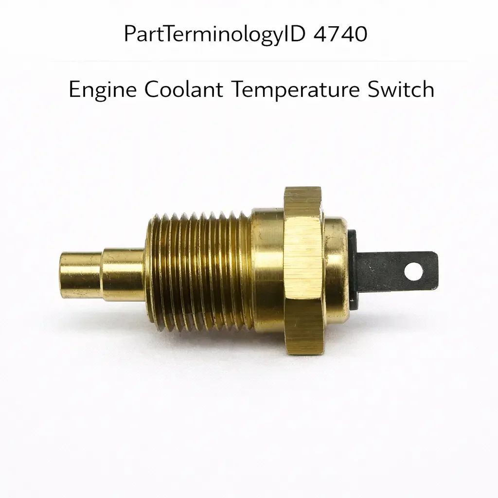
Thread Specification and Sealing
The coolant temperature switch mounts directly in the engine block, cylinder head, intake manifold, or coolant outlet housing through a threaded fitting. The thread must match the fitting in the coolant passage exactly and the switch must seal the coolant passage to prevent coolant leakage. Most coolant temperature switches use a tapered thread form that seals on the thread engagement, or a straight thread with a sealing washer or O-ring. The sealing method must be correct for the fitting type.
Common thread specifications include M14 x 1.5 metric, M16 x 1.5 metric, 3/8-18 NPT, and 1/2-14 NPT, among others. A switch with the wrong thread specification will either not engage fully in the fitting or will cross-thread. A switch that cross-threads can damage the fitting thread in the engine block or coolant housing, converting a simple switch replacement into a more involved repair.
Normally Open versus Normally Closed
Coolant temperature switches are manufactured in both normally open and normally closed configurations. A normally open switch has no continuity at rest and closes its circuit when temperature rises above the threshold. A normally closed switch has continuity at rest and opens its circuit when temperature rises above the threshold.
The correct configuration depends on the circuit the switch is used in. Warning lamp circuits that illuminate when the switch closes require a normally open switch. Fan relay circuits that activate when the switch provides a ground path require a normally open switch in most configurations. Some circuits use a normally closed switch where the absence of continuity is the active state. Installing the wrong configuration reverses the circuit logic, causing the warning to illuminate continuously during normal operation and extinguish during overtemperature, or causing the fan to run continuously during normal operation and shut off during overtemperature.
Single versus Dual Terminal Designs
Most coolant temperature switches have two terminals: a supply or signal terminal and a ground terminal, or in some designs the switch body acts as the ground through the threaded mounting in the engine block and only a single signal terminal is present. Dual terminal designs with an isolated ground are used on platforms where the engine block ground path is not reliable enough for the switch circuit, or where the switch is mounted in a non-metallic housing such as a plastic coolant outlet.
Common Failure Modes
Calibration Drift
The bimetallic element or wax-element piston within the switch can lose accuracy over time from thermal fatigue, contamination of the coolant passage around the sensing element, or physical stress from over-torquing during a previous installation. A switch with calibration drift may activate at a temperature significantly different from its nominal threshold, causing early fan activation, premature warning lamp illumination, or delayed warning that allows the engine to overheat before the lamp triggers.
Contact Wear and Oxidation
The internal contacts develop oxidation and wear through repeated thermal cycling. A switch that activates and deactivates hundreds of times per year as the engine heats and cools will develop contact resistance over time. Increased contact resistance produces a weak signal that the connected circuit may not reliably interpret, causing intermittent fan activation or intermittent warning lamp behavior.
Coolant Leakage at the Switch Thread
A coolant temperature switch that is loose, cross-threaded, or installed without the correct sealing washer or O-ring will leak coolant at the switch base. Even a slow leak that does not produce visible drips can introduce air into the cooling system over time, reducing cooling efficiency. Coolant leakage at the switch is also a fire risk if the leaked coolant contacts hot exhaust components.
Contamination of the Sensing Element
Coolant contamination from corrosion inhibitor breakdown, electrolysis, or mixing of incompatible coolant types can deposit scale on the sensing element, insulating it from the coolant temperature and causing the switch to read lower than actual coolant temperature. A switch with a contaminated sensing element will activate late or not at all, reducing the protection provided by the warning and fan systems.
Connector Corrosion
The coolant temperature switch connector is located in the engine bay and is subject to heat, moisture, and vibration. Corroded or loose connector terminals produce intermittent switch signals that are difficult to reproduce consistently during diagnosis. A warning lamp that flickers occasionally or a fan that activates and deactivates without corresponding coolant temperature changes often points to a connector issue rather than a switch contact failure.
Distinguishing the Coolant Temperature Switch from the Coolant Temperature Sensor
This distinction is the most important conceptual clarification for correct parts selection on this PartTerminologyID and the most common source of incorrect parts ordering.
The coolant temperature sensor (also cataloged as the engine coolant temperature sensor) produces a continuously variable resistance signal that changes smoothly as coolant temperature changes across the full operating range. The ECM reads this resistance to calculate the precise coolant temperature used for fuel injection quantity, ignition timing, idle speed, and emissions control. The sensor has a non-linear resistance-temperature curve and connects to the ECM through a dedicated sensor input circuit with a reference voltage and a pull-up resistor. It is a precision measurement device.
The coolant temperature switch (PartTerminologyID 4740) produces a binary on or off output at a single defined temperature threshold. It does not provide a continuous signal and does not communicate with the ECM for fuel or ignition management. It connects to warning lamp circuits, fan relay circuits, or auxiliary system control circuits. It is a threshold-triggered switching device.
The two components are not interchangeable. A coolant temperature sensor installed in a switch circuit will not produce the correct binary output. A coolant temperature switch installed in a sensor circuit will not produce the resistance curve the ECM requires and will cause the ECM to default to a fixed fuel and timing map, typically a cold-engine map, which will run rich and produce black smoke and poor fuel economy. Every catalog listing for PartTerminologyID 4740 must explicitly state that the component is a switch, not a sensor, to prevent this mismatch.
Symptoms of a Failing Coolant Temperature Switch
Overtemperature Warning Lamp Does Not Illuminate During Overheating
A switch that has failed in the open position will not illuminate the warning lamp even when coolant temperature exceeds the activation threshold. This is the most dangerous failure mode because it removes the driver's only warning of an overheating condition. A driver who does not receive the overtemperature warning may continue driving until engine damage from overheating occurs. This failure is difficult to detect proactively because the switch only operates at temperatures that indicate a fault condition.
Overtemperature Warning Lamp Illuminates During Normal Operation
A switch that has failed in the closed position, or one with significant calibration drift toward a lower activation temperature, will illuminate the warning lamp during normal operation when coolant temperature is within the normal range. Before replacing the switch on this complaint, confirm actual coolant temperature with a scan tool or infrared thermometer. If actual temperature is normal, the switch has failed in the closed state or its activation threshold has drifted below the normal operating temperature.
Cooling Fan Does Not Activate at Operating Temperature
On applications where the switch controls cooling fan activation, a switch that fails open will prevent the fan from activating. In stop-and-go traffic where ram air cooling is minimal, the engine will overheat without fan assistance. This symptom often appears first during slow-speed driving in hot weather. Confirm fan activation by bridging the switch terminals to test whether the fan activates when the switch circuit is manually closed.
Cooling Fan Runs Continuously
A fan switch that has failed in the closed position will keep the fan running at all times, including during cold start when the fan is not needed. This increases parasitic electrical load and cabin noise without providing any additional cooling benefit. It also prevents the engine from reaching normal operating temperature quickly in cold weather because the fan is circulating air through the radiator continuously.
Intermittent Warning or Fan Activation
Intermittent behavior that does not correspond to actual coolant temperature changes points to a connector fault or a contact resistance issue within the switch rather than a calibration failure. Temperature-correlated intermittent behavior, where the symptom appears consistently at a specific driving phase, points to calibration drift.
Diagnostic Process
Step One: Confirm Actual Coolant Temperature
Before testing the switch, confirm actual coolant temperature using a scan tool that reads the coolant temperature sensor signal or an infrared thermometer aimed at the thermostat housing. Knowing the actual temperature at the time of the symptom is essential for distinguishing a switch calibration fault from a genuine cooling system problem.
Step Two: Test Switch Continuity at Temperature
With the switch in the vehicle and the engine at operating temperature, test continuity between the switch terminals. A normally open switch should show continuity once coolant temperature exceeds the activation threshold. A normally closed switch should show no continuity above the threshold. If the switch does not change state at the expected temperature, it has failed or drifted from its calibration.
Step Three: Test the Switch Circuit
With the switch connector disconnected and a known-good jumper wire bridging the switch terminals, confirm the connected circuit (warning lamp, fan relay) activates correctly. If the circuit activates with the terminals bridged but not with the switch connected, the switch has failed. If the circuit does not activate even with the terminals bridged, the fault is in the circuit downstream of the switch.
Step Four: Inspect the Connector and Wiring
Disconnect the switch connector and inspect terminals for corrosion, bent pins, or loose retention. Test continuity from the switch signal terminal back to the instrument cluster or relay coil to confirm the circuit is intact.
Step Five: Verify No Coolant Leakage After Replacement
After installing the replacement switch, run the engine to operating temperature and inspect the switch thread area for coolant seepage. A seeping switch must be tightened or resealed before the vehicle is returned to service. Confirm the correct thread sealant or sealing washer is used for the specific application.
Cataloging Attributes: What to Confirm Before Listing
Activation temperature threshold: State the switching temperature in degrees Celsius and Fahrenheit. This is the most consequential attribute and must be confirmed from the OE specification. On platforms where multiple switches are used at different locations for different functions (overtemperature warning, low-speed fan, high-speed fan), each switch has a different threshold and they are not interchangeable. State the specific function and threshold for each switch in the listing.
Circuit output type: State normally open or normally closed. This is the second most consequential attribute. A wrong output type reverses the circuit logic for every function the switch controls.
Thread specification: State the thread diameter, pitch, and thread form. State whether the switch uses a tapered thread seal or a straight thread with a sealing washer, and whether the sealing washer is included. Thread mismatches produce coolant leaks. Missing sealing washers produce the same result.
Connector pin count and terminal type: State the pin count and whether the switch uses a single terminal (body ground) or a two-terminal isolated ground design.
Function designation: State the specific function the switch is designed for: overtemperature warning, low-speed fan activation, high-speed fan activation, AC lockout, or other. On platforms where multiple switches are installed in adjacent locations, function designation prevents ordering the wrong threshold switch for a specific circuit.
Switch versus sensor clarification: Every listing must explicitly state that the component is a switch, not a sensor, and include a note that the coolant temperature switch is not the same as the coolant temperature sensor. This clarification prevents a significant number of misorders on platforms where both components are listed under similar descriptions.
Common Cataloging Mistakes
The most common mistake is not clearly distinguishing the coolant temperature switch from the coolant temperature sensor in the listing title, description, and attributes. These two products are frequently confused by buyers, particularly on platforms where both are installed in adjacent coolant passage fittings and have similar external appearances. A listing for PartTerminologyID 4740 that does not explicitly state it covers a switch rather than a sensor will generate returns from buyers who needed the sensor and incorrectly ordered the switch, and vice versa.
The second mistake is omitting the activation temperature threshold. On platforms where two or three coolant temperature switches are installed at different locations for different functions, all at similar threads and connector types, the threshold is the only attribute that distinguishes them. A listing without the threshold cannot be differentiated from the other switches on the same platform, and the buyer must guess which threshold matches their application. This produces returns from every buyer whose application requires the non-default threshold.
The third mistake is not stating the circuit output type. Two switches with the same threshold and thread specification but opposite output types are electrically incompatible. On platforms where both normally open and normally closed versions were used, a listing that does not state the output type will generate returns from half of all buyers on that platform.
The fourth mistake is omitting the thread sealing method and sealing washer inclusion. On applications that require a sealing washer, a switch installed without one will leak coolant from the first use. If the listing does not state whether a sealing washer is included, the buyer may install the switch without one and return it claiming a defective product when the actual cause is missing hardware.
Related Components and Systems
Engine Coolant Temperature Sensor
The engine coolant temperature sensor is a precision measurement device that provides a continuous resistance signal to the ECM. It is cataloged separately from the coolant temperature switch and performs a different function. On many engines both the sensor and one or more switches are installed in different coolant passage locations. The sensor and switch look similar externally on some platforms and use similar thread specifications, making physical comparison unreliable for distinguishing them. The definitive distinction is the connector: the sensor connects to the ECM wiring harness, and the switch connects to the warning system or fan relay circuit.
Radiator Electric Fan Motor
The radiator fan motor is the component that the coolant temperature switch activates through the fan relay on fan-controlled applications. A fan that does not activate when the switch circuit is bridged has a motor fault or a relay fault rather than a switch fault. Always test the fan motor directly before replacing the switch on a fan activation complaint.
Fan Relay
The fan relay is the intermediate component between the coolant temperature switch and the fan motor on most applications. The switch activates the relay coil, and the relay contacts carry the motor current. A failed relay coil or failed relay contacts produce the same symptom as a failed switch. Testing the relay coil by measuring resistance between the coil terminals and testing the relay contacts by applying voltage to the coil and measuring continuity across the load contacts distinguishes a relay fault from a switch fault.
Thermostat
The engine thermostat controls coolant flow through the radiator and is the primary regulator of engine operating temperature. A stuck-open thermostat prevents the engine from reaching normal operating temperature, causing fuel enrichment and excessive wear from running consistently below the designed operating temperature. A stuck-closed thermostat causes rapid overheating. Both conditions produce temperature-related symptoms that can initially appear similar to a coolant temperature switch fault. Confirming actual coolant temperature with a scan tool or external thermometer before testing the switch isolates switch faults from thermostat faults efficiently.
Frequently Asked Questions
How do I know if my vehicle has a coolant temperature switch or only a coolant temperature sensor?
Many vehicles have both. The coolant temperature sensor connects to the ECM and is part of the main engine management wiring harness. The coolant temperature switch connects to a separate circuit for the warning lamp, fan relay, or auxiliary system. If the warning lamp circuit connects directly to a switch-type component near the thermostat housing or cylinder head rather than to a module output, the vehicle has a coolant temperature switch. A vehicle with only a coolant temperature sensor uses the ECM to drive the warning lamp and fan relay through software thresholds rather than a discrete switch.
Can I use a coolant temperature sensor instead of a switch?
No. The sensor and switch serve different functions and are not interchangeable. The sensor produces a continuously variable resistance signal. The switch produces a binary open or closed output. Installing a sensor in a switch position will produce no warning lamp activation or fan activation because the sensor does not switch its circuit in the way the warning or fan relay circuit requires. Installing a switch in a sensor position will prevent the ECM from calculating fuel and timing from coolant temperature, causing the engine to run on a fixed default map.
My overtemperature warning came on briefly and then went off. Is the switch faulty?
A brief overtemperature warning that extinguishes after a short time may indicate the engine temperature reached the switch threshold momentarily, which is a genuine overtemperature event rather than a switch fault. It may also indicate an intermittent connector fault or a switch with calibration drift near the normal operating range. Check the cooling system for adequate coolant level, thermostat function, and fan operation before attributing a brief warning to a switch fault. If the cooling system checks out correctly and the brief warning recurs, test the switch calibration by confirming the threshold at which it activates.
Does coolant type affect the coolant temperature switch?
Coolant chemistry can affect the switch sensing element over time. OAT (organic acid technology) and HOAT (hybrid OAT) coolants that have degraded past their service life can deposit corrosion products on the switch sensing element, reducing its thermal response accuracy. Using the correct coolant type for the vehicle and maintaining the coolant change interval prevents this degradation. A switch that appears to have drifted from its calibration on a high-mileage vehicle with long-overdue coolant service may recover to correct calibration after a coolant flush and replacement with fresh coolant of the correct specification.
Is the coolant temperature switch covered under any recall or service bulletin?
On certain platforms where premature coolant temperature switch failure was identified as a pattern, manufacturers have issued technical service bulletins recommending switch replacement at specific intervals or when specific symptoms appear. Check the relevant TSB database for the specific vehicle before ordering a replacement switch, as some TSBs specify an updated part number that supersedes the original and addresses the failure mechanism that caused the premature failures.
Status in New Databases
PIES/PCdb: PartTerminologyID 4740, Engine Coolant Temperature Switch
PIES 8.0 / PCdb 2.0: No change in PartTerminologyID or terminology label
Summary
The engine coolant temperature switch is a binary threshold-switching device that controls overtemperature warning indicators, electric cooling fan activation, and auxiliary system functions based on a single calibrated temperature threshold. It is distinct from the engine coolant temperature sensor, which provides a continuous variable resistance signal to the ECM for fuel and ignition management. Confusing the two generates misorders, and every listing for PartTerminologyID 4740 must explicitly identify the component as a switch rather than a sensor.
Catalog listings must state the activation temperature threshold, the circuit output type, the thread specification and sealing method, and the specific function the switch performs. The threshold is the attribute that distinguishes multiple switches installed on the same engine at different temperature set points. The circuit output type is the attribute that determines whether the switch activates the connected circuit above or below the threshold. Together these two attributes, combined with thread specification and connector pin count, define the replacement switch completely and prevent the returns that result from listings that rely on vehicle fitment alone.