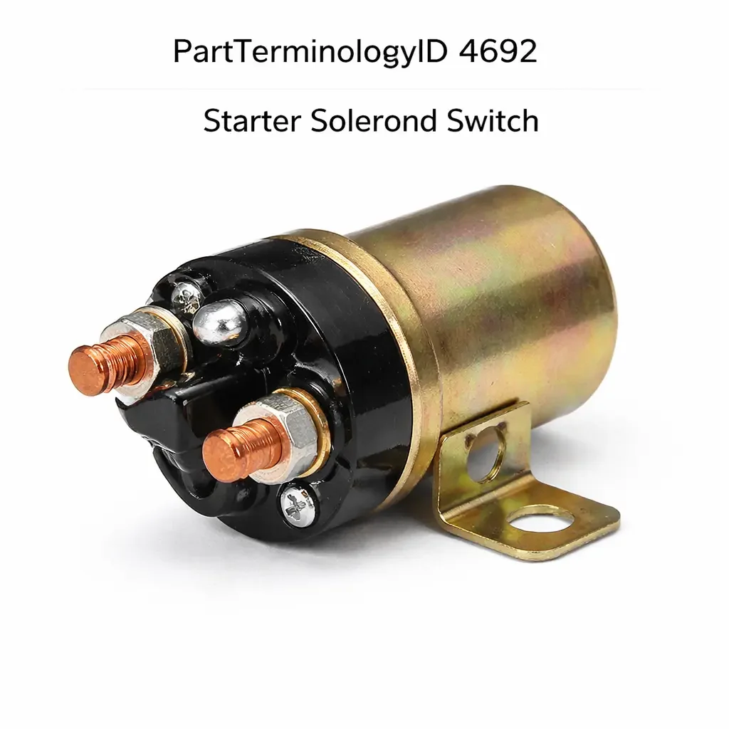
Starter Solenoid Switch (PartTerminologyID 4692): Contact Current Rating, Coil Voltage Specification, and Starter Motor Compatibility
Written by Arthur Simitian | PartsAdvisory
Introduction
The starter solenoid switch is the high-current electrical relay mounted on or integrated with the starter motor that performs two functions simultaneously when energized: it shifts the starter drive pinion into mesh with the engine ring gear, and it closes the high-current main contacts that connect the battery directly to the starter motor windings. It is the component that converts a low-current signal from the ignition switch or starter relay into the several hundred amperes of current the starter motor requires to crank the engine.
When the starter solenoid switch fails, the most common symptom is a no-crank condition where the engine does not turn over when the ignition is placed in the start position. The failure may be complete, producing a single click with no crank, or intermittent, producing a no-crank condition on some attempts but not others. Both symptoms are consistent with several possible causes including the solenoid itself, the battery, the battery cables, and the starter motor windings, making accurate diagnosis essential before parts are ordered.
The starter solenoid switch generates returns when it is selected without confirming the contact current rating, the coil voltage specification, and the terminal configuration for the specific application. These three attributes determine whether the replacement will engage correctly, survive the current demands of cranking, and connect to the vehicle's starting circuit without wiring modifications.
What the Starter Solenoid Switch Does
Pinion Engagement
When the solenoid coil is energized by the ignition switch or starter relay, the electromagnetic force pulls the solenoid plunger inward. The plunger is mechanically linked to the starter drive fork, which shifts the drive pinion forward along the armature shaft and into mesh with the engine's ring gear. The pinion must engage the ring gear fully before the main contacts close and the starter motor begins to spin at cranking speed. This sequencing prevents the pinion from slamming into the ring gear at full motor speed, which would damage both components.
The engagement sequence is managed by the solenoid's internal design. The pull-in winding draws high current to pull the plunger rapidly into the engaged position. Once the plunger reaches the engaged position, the hold-in winding, which draws lower current, maintains the plunger position while the main contacts are closed and the motor cranks.
Main Contact Closure
As the plunger reaches the fully engaged position, a copper contact disc mounted on the end of the plunger bridges the two main terminal studs of the solenoid, closing the battery-to-motor circuit. The main contacts carry the full starter motor current, which ranges from 150 amperes at no load to over 400 amperes under a cold-crank heavy load on a large displacement engine. The contact disc and the main terminal studs must be rated for this current and must maintain low contact resistance under repeated high-current closure events.
Contact resistance at the main contacts is a critical parameter. Even a small increase in contact resistance from wear or oxidation produces significant voltage drop under cranking current, reducing the voltage available to the starter motor and causing slow cranking or a no-start condition on engines with high compression ratios or in cold weather where oil viscosity increases cranking resistance.
Hold-In and Pull-In Winding Function
The solenoid coil contains two separate windings. The pull-in winding connects between the solenoid S terminal and the motor terminal, drawing current through the motor winding during engagement. The hold-in winding connects between the S terminal and ground. Both windings work together to pull the plunger rapidly into position. Once the main contacts close, the voltage across the pull-in winding drops to near zero because both ends of the winding are at battery voltage, leaving only the hold-in winding energized to maintain the plunger position.
A solenoid with a failed pull-in winding will engage slowly or not at all under cold conditions when additional pulling force is needed. A solenoid with a failed hold-in winding will pull in under normal conditions but release the plunger when the main contacts close, producing a rapid chattering engagement rather than a sustained crank.
Design and Construction
Integral Solenoid Design
On most modern starter motors the solenoid is an integral component of the starter assembly, mounted directly on the starter motor housing. The solenoid plunger engages the drive fork through a lever inside the housing. On these designs the solenoid is replaced as a standalone component if it fails, with the motor assembly remaining in place. However, on some platforms the solenoid is only available as part of a complete starter assembly and cannot be purchased separately. Confirm part availability before ordering.
Remote Solenoid Design
Some vehicles, particularly older domestic applications and certain commercial vehicles, use a remote starter solenoid mounted on the firewall or inner fender rather than on the starter motor. The remote solenoid performs only the main contact closure function; pinion engagement is handled by a separate mechanism at the starter motor. Remote solenoids are heavy-duty relay contacts designed to carry full cranking current and are typically serviceable without removing the starter motor from the vehicle.
Terminal Configuration
Starter solenoids have three or four external terminals depending on the design. The B terminal (battery) is the large stud connected to the battery positive cable. The M terminal (motor) is the large stud connected to the starter motor battery terminal. The S terminal (switch) is the small terminal that receives the ignition switch or starter relay signal. Some solenoids include an R terminal that connects to the ignition coil or ballast resistor to bypass the resistance during cranking and provide full voltage to the ignition system.
The terminal configuration, including the position and size of each terminal stud and the location of the S terminal connector, must match the vehicle's starter cable and wiring harness. A solenoid with the correct coil and contact specifications but with terminals in different positions will require cable modifications to install correctly.
Common Failure Modes
Main Contact Wear and Pitting
The most common failure mode is wear and pitting of the main contact disc and the terminal stud contact faces. Each cranking event subjects the contacts to an arc as the circuit opens and closes under high current. Over thousands of cranking events, the arc erodes the contact surfaces, developing craters and raised edges that increase contact resistance and eventually prevent the contacts from closing cleanly.
On high-mileage vehicles the contact disc can wear through entirely, producing a no-crank condition where the solenoid engages the pinion but the main contacts do not close. On some solenoid designs the contact disc is serviceable as a standalone repair part, allowing the solenoid to be rebuilt without replacing the complete assembly.
Pull-In Winding Failure
The pull-in winding is subject to thermal stress from the high current it draws during each engagement. Repeated short cranking events in rapid succession, such as an engine that requires multiple start attempts, generate more heat than the winding is designed to dissipate continuously. Extended cranking events on hard-starting engines accelerate winding degradation. A failed pull-in winding produces a solenoid that clicks but does not engage, or engages weakly only when the battery is at full charge and ambient temperature is moderate.
Hold-In Winding Failure
A failed hold-in winding produces a chattering solenoid that engages and immediately releases, producing a rapid clicking sound rather than a sustained crank. This symptom is distinctive and reliably identifies the hold-in winding as the fault before any testing is performed.
Plunger Return Spring Failure
The return spring that pulls the plunger back to the disengaged position when the solenoid coil is de-energized can weaken or break. A weakened return spring allows the plunger to rest in a partially engaged position, which can cause the pinion to drag against the ring gear when the engine is running. A broken return spring leaves the solenoid in the engaged position continuously, which will burn out the starter motor winding from continuous current flow if the ignition is left in the run position.
Symptoms of a Failing Starter Solenoid Switch
Single Click, No Crank
A single click when the ignition is placed in start, followed by no cranking, is the classic main contact failure symptom. The solenoid coil is energized and the plunger engages, producing the click, but the main contacts do not close correctly and the motor does not receive battery voltage. Distinguish this from a dead battery, which produces no click at all, and from a seized starter motor, which produces a click but the motor shaft does not turn even when battery voltage is applied directly.
Rapid Clicking
Rapid repeated clicking when the ignition is in start indicates the solenoid is engaging and releasing rapidly. This symptom has two common causes: a severely discharged battery that cannot maintain solenoid coil current once the main contacts close and begin to draw motor current, and a failed hold-in winding that releases the plunger when the pull-in winding drops out. Test battery voltage under load before replacing the solenoid on a rapid clicking complaint.
Intermittent No-Crank
An intermittent no-crank condition, where the engine starts normally on some attempts but produces a no-crank on others, points to contact pitting that produces inconsistent closure depending on the rotational position of the contact disc when the solenoid engages. Intermittent faults of this type become progressively more frequent as contact wear advances.
Slow Cranking
Slow cranking without a complete no-crank condition can result from elevated main contact resistance rather than complete contact failure. The motor receives battery voltage but with a higher than designed voltage drop across the solenoid contacts, reducing available motor voltage and cranking speed. This symptom is most noticeable in cold weather when cranking resistance is highest.
Diagnostic Process
Step One: Test the Battery
Before testing the solenoid, confirm the battery is fully charged and capable of delivering adequate cranking current. A battery with a failed cell can produce sufficient voltage at rest but collapse under cranking load, producing symptoms identical to a solenoid failure. Test battery voltage under load with a battery tester or a carbon pile tester before proceeding.
Step Two: Test the S Terminal Signal
With a multimeter set to DC voltage, measure the voltage at the solenoid S terminal while the ignition is in the start position. Battery voltage at the S terminal confirms the ignition switch, neutral safety switch, and starter relay are all functioning correctly and the solenoid coil is receiving the correct activation signal. Absent or low voltage at the S terminal points to a fault in the starting circuit upstream of the solenoid.
Step Three: Test Main Contact Voltage Drop
With the solenoid engaging and the starter attempting to crank, measure voltage drop across the solenoid main contacts by measuring voltage between the B terminal stud and the M terminal stud while cranking. A voltage drop greater than 0.5 volts across the main contacts confirms excessive contact resistance. Normal contact drop is less than 0.2 volts.
Step Four: Test Coil Continuity
With the solenoid disconnected from the vehicle, test the pull-in winding by measuring resistance between the S terminal and the M terminal. Test the hold-in winding by measuring resistance between the S terminal and the solenoid housing ground. Compare both readings to the specification for the application. An open circuit on either winding confirms a winding failure.
Step Five: Inspect Plunger and Return Spring
With the solenoid removed, manually depress and release the plunger to confirm it moves smoothly through its full travel and returns positively under spring force. A plunger that sticks or returns sluggishly points to a worn plunger bore or a weakened return spring.
Cataloging Attributes: What to Confirm Before Listing
Contact current rating: State the maximum main contact current rating in amperes. This must meet or exceed the cranking current requirement of the starter motor for the specific application. A solenoid with an undersized contact rating will overheat the contacts under normal cranking loads and fail prematurely.
Coil voltage specification: State 12-volt or 24-volt. Commercial diesel and heavy truck applications commonly use 24-volt systems. A 12-volt solenoid coil in a 24-volt system will burn out the coil winding on the first cranking event. A 24-volt solenoid coil in a 12-volt system will draw insufficient current to produce adequate magnetic force for reliable plunger engagement.
Terminal configuration: State the position and size of the B, M, S, and R terminals where applicable. Include whether the S terminal uses a spade connector, a screw terminal, or a push-on terminal. A solenoid with correct electrical specifications but incorrect terminal positions cannot be installed without cable modification.
Integral versus remote design: State whether the solenoid is designed for integral mounting on the starter motor or remote mounting on the firewall or chassis.
Plunger stroke and fork engagement: For integral solenoid applications, state the plunger stroke dimension. The plunger stroke must match the drive fork geometry of the starter motor. An incorrect stroke will not fully engage the pinion or will over-travel and damage the drive fork.
Common Cataloging Mistakes
The most common mistake is omitting the coil voltage specification on listings that cover both passenger car and commercial vehicle applications. On engine families used in both 12-volt passenger cars and 24-volt commercial trucks, a listing that does not state coil voltage will route 12-volt solenoids to 24-volt applications and vice versa. Both mismatches produce immediate failure on the first cranking event.
The second mistake is not stating the contact current rating. Two solenoids covering the same vehicle application may have different contact current ratings if the vehicle was available with different engine displacements that draw different cranking currents. A solenoid rated for a four-cylinder application installed on a large displacement V8 will have undersized contacts for the V8 cranking current and will fail under repeated cold-crank loads.
The third mistake is omitting the terminal configuration from the listing. On platforms where multiple starter solenoid designs were used across production years, different terminal configurations may share the same vehicle application range. A buyer who receives a solenoid with correct electrical specifications but incorrect terminal positions cannot complete the installation without fabricating new cable ends or extensions, producing an immediate return.
Related Components and Systems
Starter Motor
The starter motor and solenoid work as an integrated system. A solenoid that engages correctly but the motor does not spin points to a failed motor armature, field windings, or brushes rather than a solenoid fault. Conversely, a motor that spins freely when battery voltage is applied directly but does not engage through the solenoid points to a solenoid plunger or fork fault. Distinguishing between the two requires testing each component independently before ordering a replacement for either.
On applications where the solenoid is not available separately and only a complete starter assembly is offered, confirming the specific fault before ordering prevents the unnecessary expense of replacing a functional motor when only the solenoid has failed.
Neutral Safety Switch
The neutral safety switch is the component that allows the solenoid coil circuit to be completed only when the transmission is in Park or Neutral. A failed neutral safety switch will prevent the solenoid from receiving the S terminal activation signal regardless of ignition switch position, producing a symptom identical to a failed solenoid coil. Confirming S terminal voltage before testing the solenoid coil is the step that separates these two fault sources efficiently.
Battery and Battery Cables
The battery and its cables are the power source for both the solenoid coil and the main contact circuit. A battery with a failed cell will produce adequate open-circuit voltage but collapse under cranking load, producing the same no-crank symptom as a failed solenoid main contact. Battery cable resistance, particularly at corroded terminal connections, produces voltage drop that reduces available cranking voltage. These conditions must be confirmed as acceptable before the solenoid is tested or replaced.
Starter Relay
On systems where a starter relay is used between the ignition switch and the solenoid S terminal, the relay is the component that supplies activation current to the solenoid coil. A failed starter relay produces no voltage at the solenoid S terminal, which presents as a solenoid fault until S terminal voltage is tested. Always test S terminal voltage before condemning the solenoid.
Frequently Asked Questions
Why does my starter click once but not crank?
A single click with no crank is the characteristic symptom of failed or worn main contacts in the solenoid. The coil is energized and the plunger moves, producing the audible click, but the contact disc does not bridge the main terminal studs correctly. Confirm the battery is fully charged before replacing the solenoid because a severely discharged battery can produce a single click with no crank from insufficient main contact hold voltage rather than from contact wear.
Can I replace just the contact disc and terminal studs without replacing the whole solenoid?
On some solenoid designs the contact disc and terminal studs are available as a repair kit and the solenoid body can be rebuilt. This is more common on older domestic and commercial applications than on current import platforms. If the solenoid body, plunger, and coil windings are in good condition and only the contacts are worn, a contact kit repair is a cost-effective alternative to complete solenoid replacement. Confirm whether a contact kit is available for the specific solenoid before ordering a complete replacement.
Does the starter solenoid have anything to do with the fuel system or ignition?
On some older applications the solenoid R terminal connects to the ignition coil primary circuit or to a ballast resistor bypass. During cranking, the solenoid provides full battery voltage to the ignition coil by bypassing the ballast resistor, improving ignition energy during the cranking period when battery voltage is depressed by starter motor load. A solenoid without the R terminal installed in an application that requires it will produce weaker spark during cranking and may cause hard starting even when the engine turns over at correct speed.
How many times can a starter solenoid cycle before it wears out?
There is no defined cycle life specification for most solenoid designs. Longevity depends on cranking current demands, ambient temperature, frequency of use, and the quality of the solenoid construction. On passenger cars driven daily in moderate climates, a quality OE solenoid can last the vehicle's lifetime. On commercial vehicles with frequent engine starts, fleet use with multiple daily start cycles, or vehicles that require extended cranking due to a hard-starting engine condition, solenoid contact wear can develop within a few years of service. Addressing any underlying hard-start condition that causes extended or repeated cranking events preserves solenoid contact life.
Status in New Databases
PIES/PCdb: PartTerminologyID 4692, Starter Solenoid Switch
PIES 8.0 / PCdb 2.0: No change in PartTerminologyID or terminology label
Summary
The starter solenoid switch is a high-current electromechanical relay that simultaneously engages the starter pinion and closes the battery-to-motor main contacts on each cranking event. It fails through main contact wear and pitting, pull-in or hold-in winding failure, and plunger return spring degradation, each producing a characteristic symptom that guides the diagnosis before any testing begins. Accurate diagnosis requires battery testing, S terminal voltage confirmation, main contact voltage drop measurement, and coil continuity testing in that sequence.
Catalog listings for PartTerminologyID 4692 must state the contact current rating, the coil voltage specification, and the terminal configuration for every listing. The coil voltage specification is the most immediately consequential attribute because a voltage mismatch produces coil failure on the first use. The contact current rating prevents premature contact wear on high-displacement applications. The terminal configuration prevents installation failures that produce returns even when the electrical specification is correct. These three attributes, combined with vehicle fitment data, are the minimum required for a complete and accurate listing.