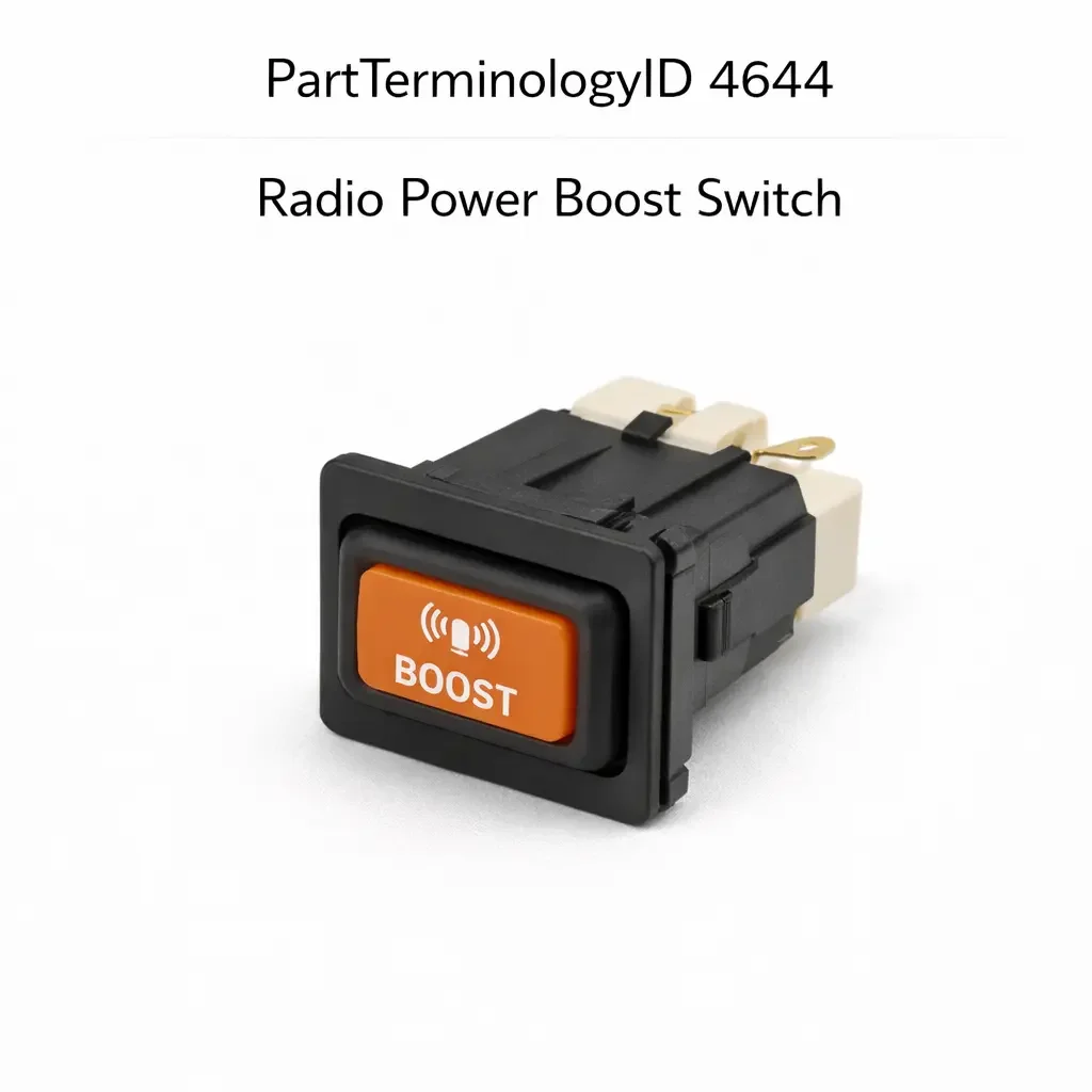
Radio Power Boost Switch (PartTerminologyID 4644): Signal Output Type, Amplifier Trigger, and Audio System Integration
Written by Arthur Simitian | PartsAdvisory
Introduction
The radio power boost switch is the control interface that activates the external amplifier circuit in a factory-equipped or dealer-installed boosted audio system. It signals the head unit or audio control module to route the audio signal through the external amplifier rather than the head unit's internal amplifier, producing higher output power to the speakers. When it fails or is replaced with an incorrectly specified part, the amplifier may not activate, may activate continuously regardless of switch state, or may produce no audio output even when the head unit is functioning correctly.
What the Radio Power Boost Switch Does
The radio power boost switch sends a command signal to the head unit, audio control module, or amplifier directly, depending on the system architecture. On systems where the head unit manages amplifier activation, the switch input signals the head unit to enable its amplifier remote output, which provides a trigger voltage to the amplifier's remote turn-on terminal. On systems with a dedicated audio control module, the switch signal is processed by the module, which then activates the amplifier through its own output circuit.
The switch does not carry audio signal current or amplifier power current. It carries only a low-current control signal. The amplifier draws its operating power directly from the vehicle's electrical system through a dedicated fused supply circuit.
On some factory systems the boost switch also adjusts the head unit's output level or EQ curve when the boost mode is active, switching between a standard output calibration and a boosted output calibration optimized for the external amplifier's input sensitivity. A replacement switch that produces an incorrect signal level for the boost input may activate the amplifier but not trigger the output level adjustment, producing distorted audio at high volume from a mismatch between the head unit output level and the amplifier's input sensitivity.
What Makes This Part Generate Returns
Signal output type is the primary return driver. Radio power boost switches use either a switched ground output, a switched voltage output, or a resistor-coded output depending on the head unit or audio module design. A switched ground switch installed in a switched voltage application will pull the module input to ground rather than supplying the expected voltage, which the module interprets as an absent or invalid signal. A resistor-coded switch with incorrect resistor values will produce a voltage level the module does not recognize as a valid boost command.
Amplifier trigger compatibility is the second return driver. On systems where the switch directly triggers the amplifier remote input rather than routing through a head unit or module, the switch output must match the amplifier's remote input voltage requirement. An output that supplies a voltage above or below the amplifier's remote trigger threshold will either fail to activate the amplifier or damage its remote input circuit.
Head unit integration is the third return driver. On platforms where the radio power boost switch is integrated into the head unit's control interface rather than being a standalone switch, a replacement that is not calibrated for the specific head unit's input circuit will not communicate correctly with the head unit regardless of physical fit.
Cataloging Attributes: What to Confirm Before Listing
Signal output type: State switched ground, switched voltage, or resistor-coded. State the output voltage or resistance value for each switch state. This is the most consequential attribute and must be confirmed from the OE specification.
Amplifier trigger voltage: State the trigger voltage supplied by the switch output on systems where the switch connects directly to the amplifier remote input. State the minimum and maximum acceptable trigger voltage range for the amplifier if available.
Head unit compatibility: State the head unit part number or family the switch is designed to interface with on platforms where the switch is calibrated for a specific head unit input circuit.
Connector pin count and type: State the pin count. Radio power boost switches range from two-pin on simple switched ground designs to four-pin or more on designs with additional outputs for EQ or output level switching.
Illumination: State whether the switch includes an active or inactive status indicator and whether the lamp circuit is continuously powered or function-switched.
Common Cataloging Mistakes
The most common mistake is listing radio power boost switches without stating the signal output type. On platforms where both a switched ground and a resistor-coded boost switch were used across different production dates or audio system option levels, a listing that does not state the output type will generate returns from buyers on the non-default audio configuration.
The second mistake is not distinguishing systems where the switch triggers the head unit from systems where it triggers the amplifier directly. These two circuit architectures require different switch output specifications and are not interchangeable. A switch designed to trigger the head unit input will not produce the correct voltage level for a direct amplifier remote trigger circuit.
Status in New Databases
PIES/PCdb: PartTerminologyID 4644, Radio Power Boost Switch
PIES 8.0 / PCdb 2.0: No change in PartTerminologyID or terminology label
Summary
PartTerminologyID 4644, Radio Power Boost Switch, is an audio system control component whose return rate is driven by signal output type mismatch and amplifier trigger incompatibility. Every listing must state the signal output type, the output voltage or resistance value for each switch state, and whether the switch triggers the head unit input or the amplifier remote input directly. Head unit compatibility and connector pin count must also be stated. A listing that relies on vehicle fitment alone without these attributes will generate returns from every buyer whose vehicle has a non-default audio system configuration.