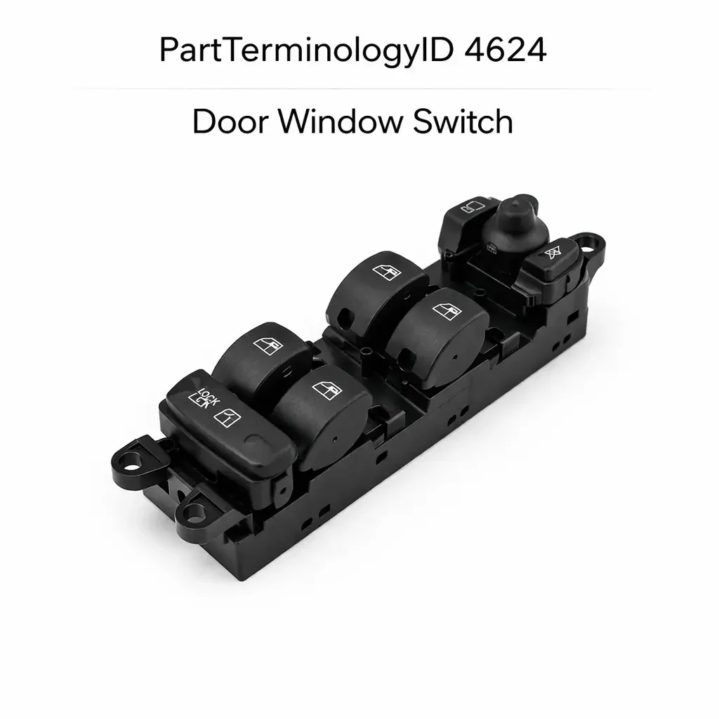
Door Window Switch (PartTerminologyID 4624): Motor Circuit Architecture, Express Function, and Window Control Module Compatibility
Written by Arthur Simitian | PartsAdvisory
Introduction
The door window switch is one of the highest-use electrical switches in the vehicle. On a vehicle driven daily, the driver's window switch may be actuated dozens of times per day, accumulating thousands of actuations per year. This frequency of use makes the door window switch one of the most commonly replaced interior switches in the aftermarket, and it makes the contact wear and failure mechanisms that affect it well understood.
What is less well understood, and what drives the return rate on PartTerminologyID 4624, is the degree to which door window switches vary in internal circuit architecture across vehicle generations, trim levels, and production runs on the same platform. A switch that physically fits the mounting cutout and matches the connector shape can still fail to operate the window correctly if its internal resistor values, contact configuration, or signal output type do not match what the window motor circuit or window control module expects. On modern vehicles with express open, express close, and anti-pinch protection, these mismatches produce symptoms that are subtle enough to pass initial inspection but reveal themselves during normal use.
This guide covers the complete picture for PartTerminologyID 4624: how the switch works, how it is constructed, how it fails, how to diagnose it accurately, and what catalog attributes must be present to prevent returns.
What the Door Window Switch Does
Up and Down Motor Commands
The most basic function of the door window switch is to command the window motor to run in the up or down direction. Each direction of movement requires a distinct switch state that produces a distinct electrical signal. On direct motor control systems the switch supplies power or ground to the motor in the appropriate polarity. On module-controlled systems the switch sends a signal to the window control module, which then commands the motor through its own output drivers.
The transition between the up and down commands must be clean and unambiguous. A switch with degraded contacts that does not produce a clean transition may cause the motor to run briefly in the wrong direction before correcting, producing a brief downward movement when the driver presses up. This symptom is a reliable indicator of contact wear on the direction-switching contact set.
Express Open and Express Close
Express window operation allows the driver to fully open or close the window with a single short press rather than holding the switch through the entire travel range. Express is managed by the window control module, which tracks the window position through motor current monitoring or a position sensor and stops the motor when the endpoint is reached.
The switch triggers express mode through a signal that the module distinguishes from a manual hold command. On some systems this distinction is made by press duration: a short press triggers express and a hold triggers manual. On others it is made by a dedicated contact set within the switch that only closes during a short press. The replacement switch must be compatible with the module's express trigger method.
Anti-Pinch Input
On windows with anti-pinch protection, the window control module monitors motor current during the close cycle and reverses the window if a current spike indicates an obstruction. The switch's role in anti-pinch is limited to ensuring the close command signal is clean and consistent. A switch that produces a noisy or intermittent close signal can cause false anti-pinch reversals by making the module unable to distinguish a normal close command from an obstruction event.
Driver Master Switch Functions
The driver's door contains a master switch assembly that controls all windows in the vehicle. The master switch includes individual rocker controls for each window and typically a window lockout button that disables the passenger window switches. The number of window control positions in the master switch, the wiring configuration for each window circuit, and the connector pin count are all specific to the number of windows the vehicle has and the control architecture used.
A master switch from a four-window vehicle is not interchangeable with one from a two-window vehicle, and a master switch from a vehicle without express function is not interchangeable with one from an express-equipped vehicle, even if all three share the same mounting dimensions and a similar external appearance.
Passenger Window Switches
Passenger window switches are simpler assemblies that control only the window in their respective door. They connect to either the master switch assembly through a sub-harness or directly to the window control module for their door zone. On some platforms all passenger switches are identical. On others the front passenger switch differs from the rear switches due to the inclusion of an express function on the front passenger window that is absent from the rear windows.
Circuit Architecture Variations
Circuit architecture is the most consequential compatibility attribute for window switch selection and the one most commonly omitted from catalog listings.
Direct Motor Control
On older vehicles, typically pre-mid-1990s on most domestic platforms, the window switch connects directly to the window motor through a relay or directly through the switch contacts. The switch reverses motor polarity by routing current through the motor in opposite directions depending on which way the rocker is pressed. The switch carries the full motor current in this architecture, typically 10 to 20 amperes for a window motor under load, and the contacts must be rated accordingly.
Direct motor control switches use a bridge contact configuration internally. When the rocker is pressed in one direction, contacts A and B close. When pressed in the other direction, contacts C and D close, routing current through the motor in the opposite direction. The bridge configuration is the defining characteristic of direct motor control window switches and is fundamentally different from signal input switches used on module-controlled systems.
Window Control Module Signal Input
On modern vehicles the window switch sends a low-current signal to a window control module, which drives the motor through its own H-bridge output circuit. The switch carries only signal current, typically a few milliamperes, and the contact current rating is not a limiting factor. The internal contact configuration is matched to the module's input circuit expectations rather than to the motor polarity requirement.
Signal format on module-controlled systems varies significantly. Switched ground inputs, switched voltage inputs, resistor-coded single-wire inputs, and multiplexed bus inputs are all used across different platforms and model years. A resistor-coded input is particularly common on current platforms because it allows multiple switch functions to be communicated over a single signal wire by producing different resistance values for up, down, express, and neutral positions.
Resistor-Coded Switches
Resistor-coded window switches are the most common source of compatibility failures in the current aftermarket. The switch contains a resistor network that produces a specific voltage level at the module input pin for each switch position. The module is calibrated to recognize specific voltage thresholds as specific commands. A replacement switch with different resistor values will produce voltage levels that fall outside the module's calibrated command windows, causing the module to ignore the command or misidentify it.
Resistor values in window switches are platform and production date specific. On platforms where the window control module was revised mid-production-run, the new module calibration may have different voltage thresholds that require a switch with different resistor values than the original. A listing that does not state resistor values cannot distinguish between these variants, and a buyer whose vehicle was built after the mid-run revision will receive a switch that worked on the pre-revision vehicle but does not work on theirs.
LIN Bus and CAN Bus Systems
On luxury and premium platforms, the window switch is a multiplexed module that communicates over the LIN bus or CAN bus. The switch module contains its own microcontroller that monitors the switch state and transmits a digital command message to the window control module or BCM. In this architecture the replacement switch must be compatible with the bus protocol and message format. Generic switches that do not include the correct bus interface hardware will not communicate with the module regardless of physical fit.
Design and Construction
Rocker Switch
The rocker is the most common window switch actuator. A rocker pivots on a center axis and actuates the up contact set when the top is pressed and the down contact set when the bottom is pressed. The rocker returns to center when released, making both position contact sets momentary. On some designs a partial press activates manual mode and a full press activates express mode by engaging a second contact layer.
Sliding Actuator
Some platforms use a sliding actuator that moves forward for up and backward for down, or left and right depending on the orientation in the door panel. The sliding design is common on Japanese and European platforms from the 1990s and provides a tactile feel that many drivers find intuitive. Internally the sliding actuator operates the same contact sets as a rocker design.
Master Switch Panel
The driver's master switch panel integrates individual rockers or buttons for each window zone into a single assembly. The panel may also include door lock controls, mirror controls, and window lockout in the same housing. The window switch function within a master panel assembly may or may not be serviceable as a standalone component. On some platforms individual window rockers can be replaced within the panel. On others the entire panel is replaced as a unit.
Illumination
Window switches on most current vehicles include backlight illumination for visibility at night. Illuminated switches have additional terminals for the lamp supply circuit. A non-illuminated replacement in an illuminated position will leave the switch dark and may generate a fault code on BCM-monitored lamp circuits. On master switch panels with multiple illuminated functions, the lamp circuit may be shared across the panel, and a switch without the lamp contact will interrupt the shared circuit and extinguish all illumination in the panel.
Common Failure Modes
Contact Wear on High-Frequency Axes
The driver's window switch is actuated more frequently than any other window switch in the vehicle. The up and down contacts in the driver's switch wear faster than those in passenger switches. The express contact set, if present, wears at the same rate as the manual contact set because express is triggered by the same contact on most systems. Contact wear produces increased resistance that causes the module to receive out-of-range signals, resulting in missed commands or commands misidentified as a different function.
Contamination from Door Seal Degradation
Window switches are located in the door panel, adjacent to the window opening. On vehicles with degraded door seals or window run channels, water can enter the door cavity and reach the switch housing through the door panel. Water intrusion events that saturate the door panel can flood the switch housing and contaminate the contacts. This failure mode is more common on higher-mileage vehicles where door seals have become brittle.
Connector Pin Damage
The door window switch connector is subject to the same door harness flexing as the door lock switch connector. On high-mileage vehicles the door harness section that passes through the door hinge area may develop wire fatigue or insulation cracking, producing intermittent circuit faults that present as intermittent switch function. Testing the harness between the door and the body is a necessary step in any intermittent window switch diagnosis.
Housing and Actuator Damage
Physical damage to the rocker actuator from impact, debris entering the door panel cavity, or heavy-handed operation can crack the actuator or distort the housing geometry. A cracked actuator may still depress the contact plunger but with reduced travel, causing the contact to close incompletely and produce a weak signal.
Lockout Button Failure
The window lockout button in the master switch assembly can fail independently of the window control contacts. A failed lockout button stuck in the locked position will prevent all passenger window switches from operating. This is sometimes misdiagnosed as a multiple window switch failure because several switches appear to stop working simultaneously. Testing the lockout circuit before replacing multiple window switches is essential.
Symptoms of a Failing Door Window Switch
Window Moves in One Direction Only
A window that moves up but not down, or down but not up, from the switch typically points to a failed contact set for the non-functioning direction. Distinguish a switch fault from a module output fault by testing the switch contact directly with a multimeter. If the contact closes correctly but the window still does not move in that direction, the fault is in the module output or the motor circuit for that direction.
Express Function Does Not Work
If the window moves in both directions with a held switch but does not travel to the endpoint on a short press, the express function has failed. On systems where express is triggered by a dedicated contact layer, test that contact. On systems where express is triggered by the same contact as manual and distinguished by press duration, the module's express logic has likely failed rather than the switch.
Window Responds Slowly or Misses Commands
Slow response or missed commands, where the window sometimes moves and sometimes does not on the same switch input, point to high contact resistance from wear or contamination. The switch is producing a signal, but the signal level is below the module's valid command threshold on some actuations. This failure mode is intermittent in early stages and becomes consistent as wear progresses.
All Windows Stop Working from Master Switch
If all windows stop responding to the master switch simultaneously but work correctly from individual door switches, the fault is in the master switch assembly or its power supply rather than in individual window circuits. Check the master switch power supply fuse and confirm power at the master switch connector before replacing the assembly.
Window Lockout Appears Active Without Button Press
If passenger window switches stop working and the lockout indicator is not lit, but the lockout contact in the master switch has failed in the closed position, the module is receiving a lockout command regardless of the button state. Test the lockout contact in the master switch before diagnosing a module fault.
Diagnostic Process
Step One: Isolate by Zone
Determine which windows are affected. All windows from master switch only, one window from all switches, one window from master only, or one window from its own switch only. Each pattern points to a different fault location and prevents unnecessary switch replacement.
Step Two: Check Fuses and Power Supply
Verify the window circuit fuse for the affected zone. On vehicles with a separate fuse for each window zone, a blown zone fuse disables only that window. Confirm supply voltage at the master switch connector and at individual switch connectors for affected windows.
Step Three: Test Switch Contacts
With the switch disconnected, test each contact set in both directions with a multimeter. For resistor-coded switches, measure the resistance in each position and compare to the specification. Any position that does not produce the expected result confirms a switch fault for that position.
Step Four: Bypass Test
On direct motor control systems, confirm the motor runs correctly by applying battery voltage directly to the motor terminals in both polarities. On module-controlled systems, use scan tool bidirectional control to command the motor directly through the module. If the motor responds to direct commands but not to switch input, the fault is in the switch or the wiring between the switch and the module input.
Step Five: Inspect Harness Through Door Hinge
On intermittent complaints, flex the door harness through the hinge area by opening and closing the door while monitoring continuity on the switch signal circuit. A circuit that opens or shorts during door movement confirms wire fatigue in the hinge area as the fault source.
Step Six: Clear DTCs and Verify
After repair, clear all stored DTCs and cycle each window through full travel in both directions. Confirm express function on equipped windows. On module-controlled systems with anti-pinch, perform the endpoint initialization procedure if required by the service documentation.
Cataloging Attributes: What to Confirm Before Listing
Circuit architecture: Direct motor control or module signal input. This is the foundational compatibility attribute. A direct motor control switch carries full motor current through bridge contacts. A module signal input switch carries only signal current through a resistor network or switched input. They are not interchangeable.
Resistor values for coded inputs: For resistor-coded applications, state the resistance value for each position: up, down, express up, express down, and neutral. Production date breakpoints where resistor values changed must be noted. A listing without resistor values for a coded switch application is incomplete.
Express function: State whether express is included and which directions support express. Some applications have express open only, others have express open and close. A switch without express close installed in an express-close application removes that function.
Master versus passenger designation: State explicitly. Master switch assemblies have significantly more terminals and internal contact sets than passenger switches. A passenger switch in the driver's position removes all-window control.
Number of window zones in master switch: State the number of window positions in the master switch. A four-window master switch is not interchangeable with a two-window master switch even if the mounting dimensions are identical.
Window lockout inclusion: State whether the master switch includes a window lockout function and contact set.
Illumination: State whether the switch includes illumination and the lamp circuit terminal count.
Connector pin count and body type: State the pin count for both the master switch and passenger switch variants.
Common Cataloging Mistakes
The most common mistake is listing window switches by vehicle application without stating circuit architecture. On platforms that transitioned from direct motor control to module-controlled window systems mid-generation, both system types share the same vehicle application year range. A listing that does not state the architecture will route direct motor control switches to module-controlled vehicles and vice versa. The result is a switch that physically installs but produces no window movement or, on direct motor control switches installed in module-controlled systems, potentially routes motor current to a module signal input and damages the module.
The second most common mistake is omitting resistor values on coded switch applications. This omission is the primary driver of returns on current platforms. Two switches that correctly list the same vehicle application but have different resistor values will produce different voltage levels at the module input. The module will recognize only one of them as producing valid command signals. Without resistor values in the listing, the buyer has no way to confirm which switch is correct for their vehicle's production date.
The third mistake is failing to specify express function coverage direction. Listing a switch as express-compatible without stating whether express covers only the open direction or both open and close is insufficient. A buyer whose vehicle has express close will order an express-compatible switch, receive one that covers only express open, and find that the express close function does not work. State both directions explicitly.
The fourth mistake is not distinguishing two-window master switches from four-window master switches on platforms that offered both body configurations. Coupe and convertible variants of the same platform have a two-window master switch. Sedan and wagon variants have a four-window master switch. Both share the same platform name in the catalog but require different master switch assemblies.
Related Components and Systems
Window Motor
The window motor is the component that physically drives the window regulator. Each window has a dedicated motor. When a window fails to move in one direction from the switch, testing the motor directly by applying battery voltage to its terminals in both polarities is the most efficient way to confirm whether the fault is in the switch circuit or the motor. A motor that runs correctly when powered directly but not from the switch confirms a switch or wiring fault. A motor that does not run when powered directly, or runs in one direction only, confirms a motor fault. Motor testing takes less than two minutes and prevents unnecessary switch replacements on motor fault complaints.
Window Control Module
On module-controlled systems, the window control module receives switch signals, manages express travel, monitors motor current for anti-pinch detection, and drives the motor through its own output circuit. A failed module output driver will prevent one or more windows from responding to switch input even when the switch is functioning correctly. Scan tool bidirectional control of the motor through the module is the fastest way to distinguish a switch input fault from a module output fault. If the motor responds to module commands through the scan tool but not to switch input, the fault is in the switch or the wiring between the switch and the module input pin.
Door Harness and Hinge Section
The door harness section that passes through the door hinge area flexes with every door opening and closing cycle. Over tens of thousands of door cycles on a high-mileage vehicle, individual conductors in the hinge section can develop fatigue breaks in the copper strands while the insulation remains intact and the break is invisible externally. A conductor with a fatigue break will show correct resistance during bench testing but will open intermittently under the flexing stress of door movement. Any intermittent window switch complaint on a high-mileage vehicle should include a harness flex test through the hinge area before the switch is replaced.
Window Regulator
The window regulator is the mechanical linkage that converts motor rotation into window glass vertical movement. A binding or worn regulator increases the load on the motor, which increases motor current draw. On module-controlled systems with current-based anti-pinch protection, a high-friction regulator can cause the module to interpret normal window travel as an obstruction and reverse the window. If a window reverses during normal travel without an obstruction after a switch replacement, inspect the regulator for binding before replacing the module.
Body Control Module
On vehicles where the BCM manages the window control function directly rather than through a dedicated window control module, a BCM input fault can produce symptoms identical to a window switch failure. If the switch and wiring test correctly but the BCM still reports a fault on the window switch input circuit, the BCM input channel should be tested before the BCM is replaced. BCM replacements on current vehicles typically require programming and are significantly more expensive than switch replacements.
Frequently Asked Questions
Why does my driver's window work from the door switch but not from the master switch?
This indicates the fault is in the master switch contact for the driver's window zone, not in the window motor, module, or individual door switch. The individual door switch communicates with the window motor or module through a separate circuit from the master switch. When the individual switch works but the master switch does not produce movement for that window, the master switch contact set for that window zone has failed while the rest of the master switch continues to function. Test the master switch contact for the driver's window position specifically before replacing the entire master switch assembly.
Can I use a window switch from a higher trim level on my base trim vehicle?
Only if the circuit architecture and connector are compatible. A higher-trim switch may include express function contacts that are not present on the base switch. On direct motor control systems the express contacts are simply unused on a base vehicle and the switch will function for the manual control positions. On module-controlled systems the additional express contacts may produce signals the base module does not expect, generating fault codes. On resistor-coded systems a switch from a different trim level will almost certainly have different resistor values calibrated for the higher-trim module. Trim level substitution is not recommended without confirming circuit compatibility.
My rear windows stopped working after I replaced the master switch. What went wrong?
If rear windows worked before the master switch replacement but not after, the most likely cause is a connector seating issue. The master switch connector on most platforms is a multi-pin connector that controls all window zones. A connector that is not fully seated will produce intermittent or absent signals on some pins while others work correctly. Remove and firmly reseat the connector, confirming the retention tab clicks. If rear windows still do not work after confirming the connector, compare the pin count and terminal assignments of the replacement switch against the original to confirm the correct part was supplied.
How do I reset the window module after replacing the switch?
On most direct motor control systems no reset is required. On module-controlled systems with express and anti-pinch, the module may need its endpoint positions re-initialized after power has been interrupted. The initialization procedure typically involves holding the window in the full up position for several seconds, then holding it in the full down position for several seconds, allowing the module to re-learn the endpoints. The specific procedure varies by platform and should be confirmed in the service documentation before the installation is considered complete. Skipping the initialization on a system that requires it will result in the window stopping short of the fully open or closed position and may trigger false anti-pinch reversals.
Does water damage from a failed door seal always require switch replacement?
Not always. If the water intrusion event is minor and caught early, cleaning the switch contacts with electrical contact cleaner and allowing the switch to dry completely may restore function. If the contacts show visible corrosion or the switch housing has absorbed water and warped, replacement is necessary. More importantly, the door seal or window run channel that allowed the intrusion must be repaired before the new switch is installed. A new switch installed in a door that continues to leak will fail from the same cause within a short period.
Status in New Databases
PIES/PCdb: PartTerminologyID 4624, Door Window Switch
PIES 8.0 / PCdb 2.0: No change in PartTerminologyID or terminology label
Summary
The door window switch is the highest-use electrical switch in the vehicle interior and one of the most return-prone parts in the aftermarket when cataloged without its critical attributes. Circuit architecture, resistor values for coded systems, express function coverage, master versus passenger designation, window zone count, and connector pin count are all required attributes for a complete and accurate listing.
The transition from direct motor control window systems to module-controlled systems with resistor-coded switch inputs is the source of the majority of fitment failures on this PartTerminologyID. A listing that does not distinguish between these two architectures will generate returns from every buyer whose vehicle is on the opposite side of that transition from what the listing assumes. Resistor value omission on coded applications generates returns within a single platform from buyers whose vehicle was built after a mid-run module calibration revision.
PartTerminologyID 4624, Door Window Switch, covers one of the widest ranges of internal design variation in the switch category. Correct cataloging requires treating each circuit architecture as a distinct product type, not a variation of the same product.