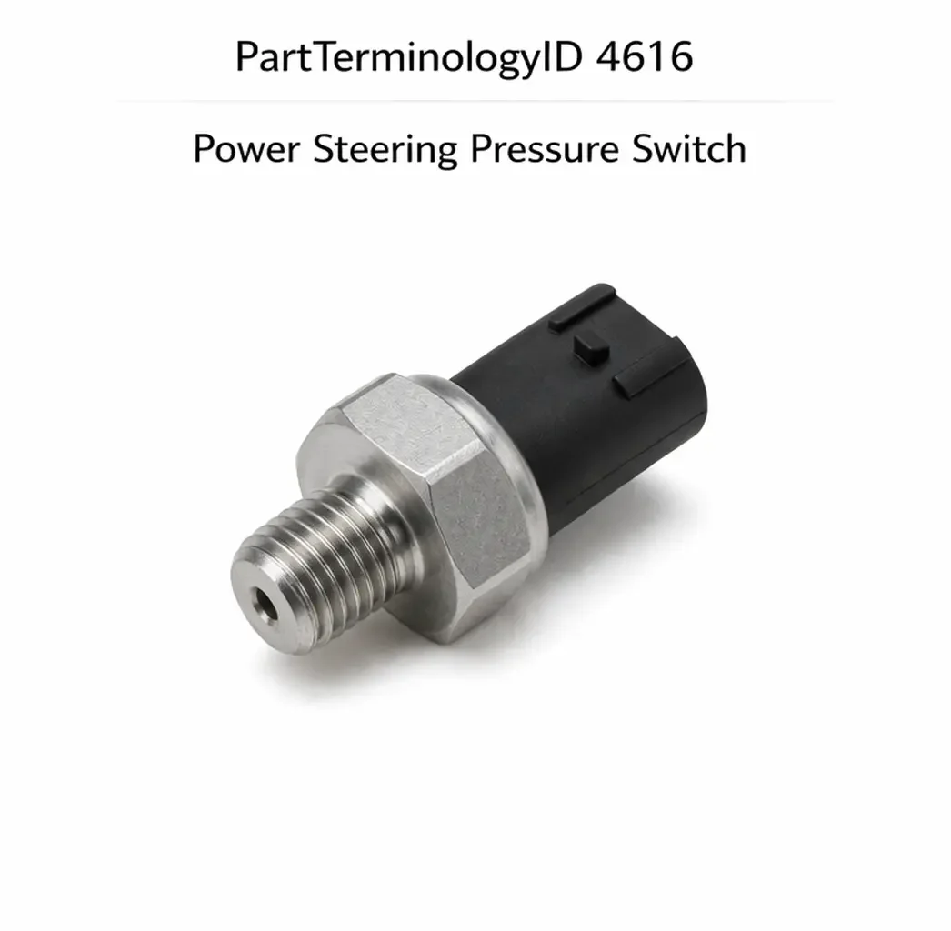
Power Steering Pressure Switch (PartTerminologyID 4616): Pressure Threshold, Circuit Output Type, and Idle Compensation Compatibility
Written by Arthur Simitian | PartsAdvisory
Introduction
The power steering pressure switch is a hydraulic pressure-sensing electrical switch mounted in the high-pressure line of the power steering system. Its primary function is to signal the engine control module or idle speed control system when the power steering pump generates high hydraulic pressure, which occurs when the driver turns the steering wheel toward full lock. At full lock or near-full lock, the power steering pump load on the engine increases substantially, and without compensation the engine may stall, particularly at idle or low speed.
The switch closes or opens its electrical circuit when steering system pressure rises above its calibrated threshold, sending a signal to the ECM that causes the idle speed to increase by a calibrated amount to compensate for the additional pump load. On vehicles with electronic throttle control this compensation is managed by the ECM through the throttle actuator. On older vehicles with a mechanical idle speed control it may be managed through the idle air control valve or a direct solenoid.
Beyond idle compensation, the power steering pressure switch signal is used on some platforms as an input to the engine cooling fan control system, activating the electric cooling fan at high steering load to manage underhood temperatures during low-speed maneuvering. On these applications a failed switch not only affects idle quality but can contribute to elevated coolant temperatures during parking lot maneuvers.
Understanding the switch's function, failure modes, and critical fitment attributes is essential for correct diagnosis and replacement selection.
What the Power Steering Pressure Switch Does
Idle Speed Compensation
When the power steering pump operates at high load, it draws significant mechanical energy from the engine crankshaft through the accessory drive belt. This load increase can cause engine RPM to drop at idle, producing a rough or stalling condition. The power steering pressure switch detects the high-pressure condition and signals the ECM to increase idle speed before the RPM drop becomes noticeable to the driver.
The timing of this compensation matters. The switch must close or open at a pressure threshold that anticipates the RPM drop rather than reacting to it after the fact. A switch with a threshold set too high will not signal the ECM until the pump is already at maximum load, arriving too late for smooth compensation. A switch with a threshold set too low will trigger idle compensation during normal straight-ahead driving at moderate steering effort, causing unnecessary idle speed increases.
Cooling Fan Activation
On vehicles where the power steering pressure switch also controls or contributes to the cooling fan activation logic, the switch signals the ECM or the fan control module when the steering system is under high load during low-speed maneuvering. The ECM activates the electric cooling fan to manage the additional heat generated by the power steering pump and to compensate for reduced ram air cooling at low vehicle speeds. A failed switch in this application can cause the fan to remain inactive during slow parking maneuvers, contributing to elevated underhood temperatures.
Signal to the ECM
The switch communicates with the ECM through a simple switched circuit on most applications. When pressure rises above the threshold, the switch closes a circuit to ground or opens a circuit from a reference voltage, depending on whether the switch is a normally open or normally closed design. The ECM monitors the input and responds according to its calibration. On more modern platforms the switch signal is processed by the power steering control module before being communicated to the ECM over the vehicle data bus.
Design and Construction
Switch Body and Thread Specification
The power steering pressure switch is mounted directly in the high-pressure power steering line, either at a fitting on the power steering pump outlet, at a fitting on the steering rack inlet, or at a T-fitting in the high-pressure line. The switch body must seal against high-pressure fluid, which on a power steering system can reach 1,200 to 1,500 psi under full lock conditions.
The thread specification is critical. Power steering pressure switches use a variety of thread forms including metric threads, SAE threads, and in some cases inverted flare fitting threads. A switch with the wrong thread specification will either not engage correctly in the fitting or will cross-thread and damage the fitting, potentially causing a power steering fluid leak at high pressure.
Pressure Activation Threshold
The switch is calibrated to change state at a specific hydraulic pressure, typically expressed in psi or bar. Common thresholds range from 150 psi to 450 psi depending on the application and the steering system design. The threshold is set during manufacturing and is not adjustable in the field.
A replacement switch with a threshold that does not match the original will change state at the wrong point in the steering cycle, producing either early idle compensation that activates during normal driving or late compensation that allows an RPM drop before the ECM responds.
Normally Open versus Normally Closed
Power steering pressure switches are available in both normally open and normally closed configurations. A normally open switch has no continuity at rest and closes its circuit when pressure exceeds the threshold. A normally closed switch maintains continuity at rest and opens its circuit when pressure exceeds the threshold. The correct type is determined by the ECM's input circuit design. Installing the wrong type will invert the signal, causing the ECM to see the high-pressure condition as the normal state and the low-pressure condition as the high-load state, producing continuous idle compensation during straight-ahead driving and no compensation during actual high-load steering.
Electrical Connector
Power steering pressure switches use a variety of connector designs from one-pin to three-pin depending on the application and whether the switch includes an additional pressure warning circuit. The connector type must match the vehicle harness connector. A switch with the correct pressure threshold and thread specification but the wrong connector type cannot be connected to the vehicle harness without a wiring repair.
Common Failure Modes
Diaphragm or Sensing Element Failure
The internal pressure-sensing element, typically a diaphragm or piston that deflects under hydraulic pressure, can develop fatigue cracks or seal degradation after extended exposure to high-pressure fluid and thermal cycling. A failed sensing element may prevent the switch from changing state at the correct pressure, cause it to change state at the wrong pressure, or allow fluid to enter the electrical portion of the switch.
Fluid Contamination of Contacts
If the seal between the hydraulic portion and the electrical portion of the switch fails, power steering fluid can migrate into the contact chamber and contaminate the electrical contacts. This typically causes the switch to fail in one fixed state, either always open or always closed, regardless of actual system pressure. Power steering fluid contamination of the switch contacts is also an indicator that the switch seal has failed and that fluid may be entering the wiring harness, which should be inspected and dried before the new switch is installed.
Connector Corrosion
The power steering pressure switch is located in the engine bay, where it is exposed to heat, moisture, and road contamination. The wiring connector is subject to terminal corrosion, particularly on vehicles operated in humid or salt-exposed environments. Corroded terminals produce a high-resistance connection that may prevent the ECM from receiving a clean signal, causing intermittent idle compensation anomalies that are difficult to reproduce during diagnosis.
Thread Damage from Over-Torquing
Power steering pressure switch fittings are machined into aluminum pump housings or steel line fittings. Over-torquing during a previous installation can damage the threads in the fitting, making it impossible to seal a new switch correctly. If the switch fitting shows evidence of thread damage, the fitting must be repaired with a thread insert before the replacement switch is installed.
Symptoms of a Failing Power Steering Pressure Switch
Engine Stalls or Stumbles When Turning at Low Speed
This is the most common and most easily reproduced symptom. The engine RPM drops noticeably when the steering wheel is turned to near-full lock at idle or low speed, and in severe cases the engine stalls. The ECM is not receiving the high-pressure signal from the switch and is not initiating idle speed compensation. Reproduce the symptom by turning the wheel to full lock with the vehicle stationary and noting whether the RPM drops.
Engine Idle Is Continuously High
A switch that has failed in the closed position will continuously signal the ECM that the steering system is under high load. The ECM will maintain an elevated idle speed at all times, including during straight-ahead driving where no compensation is needed. Continuous high idle accompanied by no other symptoms is a strong indicator of this failure mode.
Cooling Fan Runs Continuously at Low Speed
On applications where the switch contributes to cooling fan activation, a switch stuck in the closed position may keep the cooling fan running at low speed continuously. This is not always a noticeable problem but may be reported as unusual fan noise or unusual battery drain if the fan draws significant current.
ECM Fault Codes for Power Steering Pressure Switch Circuit
The ECM monitors the switch input for circuit continuity and in some cases for plausibility. A switch that is always open or always closed when the ECM expects the opposite state, or a switch circuit with an open or short, will generate a DTC. These codes direct the diagnosis to the switch circuit before any symptom-based testing is needed.
Diagnostic Process
Step One: Retrieve DTCs
Scan the ECM for DTCs referencing the power steering pressure switch input circuit. Codes indicating an open circuit, short to ground, or signal stuck high or low confirm the switch circuit as the fault area.
Step Two: Reproduce the Symptom
With the vehicle at operating temperature and at idle, turn the steering wheel to full lock and hold it there for several seconds. Note whether the engine stumbles or stalls. If it does, the idle compensation function is not working, confirming a switch or circuit fault.
Step Three: Test the Switch Circuit
With the switch connector disconnected, use a multimeter to confirm whether the switch is normally open or normally closed at rest. Then apply pressure to the switch using a hand pump or by reconnecting it to the system and observing whether it changes state during full-lock steering. Confirm the switch changes state at a pressure appropriate for the application.
Step Four: Inspect the Connector and Wiring
Inspect the switch connector terminals for corrosion and the wiring for damage. Measure resistance from the switch signal terminal back to the ECM input pin to confirm the circuit is intact.
Step Five: Confirm Correct Threshold After Replacement
After installing the replacement switch, road test the vehicle and confirm the engine maintains stable idle when the steering wheel is turned to full lock. Confirm no new DTCs are present.
Cataloging Attributes: What to Confirm Before Listing
Pressure activation threshold: State the switching pressure in psi and bar. This is the most consequential attribute and must be confirmed from the OE specification. Two switches for the same vehicle application that differ in threshold produce different idle compensation timing. Do not omit this value from any listing.
Circuit output type: State normally open or normally closed explicitly. This attribute is frequently omitted and is the most likely cause of a return when wrong, because the symptom of a reversed switch type is continuous idle compensation rather than absent compensation, which is a less obvious failure than a stall.
Thread specification: State the thread diameter, pitch, and thread form. Confirm whether the fitting uses a sealing washer or a tapered thread seal, and whether a new sealing washer is included with the replacement switch.
Connector type and pin count: State the connector body type and pin count. Include whether the connector is included with the switch or whether it uses the vehicle's existing harness connector directly.
Cooling fan function: State whether the switch is used only for idle compensation or also for cooling fan activation on the specific application. Buyers replacing a switch on a vehicle with fan activation function need to know the replacement covers that function.
Common Cataloging Mistakes
The most common mistake is omitting the pressure threshold from the listing entirely and relying only on year, make, model, and engine. On platforms where the power steering system was revised mid-production-run with a different pump and a different threshold calibration, both production variants share the same vehicle application but require different switches. A listing without the threshold value provides no way for the buyer to confirm which variant their vehicle has.
The second mistake is omitting the normally open versus normally closed designation. This omission accounts for a significant portion of returns on this part category because the incorrectly typed switch installs and connects without any obvious physical difference from the correct one. The symptom it produces, continuous high idle, may not be immediately attributed to the new switch.
The third mistake is not specifying whether a sealing washer is included. A switch that requires a sealing washer installed without one will leak power steering fluid at the switch fitting under high-pressure conditions. If the original switch used a crush washer that was left in the fitting during switch removal, installing the new switch without removing the old washer will prevent correct seating and produce the same leak.
Related Components and Systems
Power Steering Pump
The power steering pump generates the hydraulic pressure that the switch monitors. A pump that is worn or low on fluid will not reach normal system pressure during full-lock steering, which means the switch may not receive the pressure needed to change state even when it is functioning correctly. If the idle stumble at full lock persists after a switch replacement, inspect the power steering pump for wear and confirm the fluid level and condition. A whining noise from the pump during steering input is a common indicator of pump wear or low fluid.
Idle Air Control Valve
On older vehicles with a mechanical throttle and an idle air control valve, the ECM responds to the power steering pressure switch signal by increasing the idle air control valve opening to raise idle speed. A worn or carbon-fouled IAC valve may not respond to the ECM command quickly enough to prevent an RPM drop even when the switch is functioning correctly. When diagnosing a low idle at full lock on an older vehicle, confirm the IAC valve responds correctly to ECM commands before attributing the fault entirely to the switch.
Electric Cooling Fan Control Module
On vehicles where the power steering pressure switch contributes to cooling fan activation, the fan control module or the ECM fan output driver is the downstream component that responds to the switch signal. A failed fan control module will prevent the cooling fan from activating during high steering load regardless of switch condition. Confirm the fan activates correctly through scan tool bidirectional control before replacing the switch on a cooling fan complaint.
Power Steering High-Pressure Line
The switch mounts into a fitting in the high-pressure line. If the high-pressure line is being replaced as part of a power steering service, the switch must be transferred to the new line or a new switch must be specified with the correct fitting thread for the replacement line. On some platforms the switch fitting is integral to the line assembly and the line must be ordered with the switch provision.
Frequently Asked Questions
Can a bad power steering pressure switch cause the engine to stall?
Yes. If the switch fails to signal the ECM when the power steering pump is under high load, the ECM will not increase idle speed to compensate for the additional pump load. At idle or very low speed with the wheel turned to full lock, the engine RPM can drop low enough to stall. This is the most common symptom of a failed power steering pressure switch and is most noticeable on vehicles with smaller displacement engines where the pump load represents a larger proportion of available torque.
How do I know if my vehicle uses the power steering pressure switch for cooling fan control?
Check the vehicle's wiring diagram for the cooling fan control circuit. If the power steering pressure switch circuit connects to the ECM or fan control module in a path that includes the cooling fan output, the switch is involved in fan control. Alternatively, with the vehicle at operating temperature and at idle, turn the steering wheel to full lock and hold it. On vehicles where the switch controls the fan, the electric cooling fan should activate or increase speed within a few seconds of the full-lock condition.
Why does my engine idle high after replacing the power steering pressure switch?
A continuously elevated idle after switch replacement typically means the new switch is normally closed when the application requires a normally open switch, or vice versa. The ECM is receiving a continuous high-pressure signal and is maintaining idle compensation at all times. Verify the output type of the replacement switch against the specification for the vehicle and replace with the correct type if the output type does not match.
Does the power steering pressure switch affect power steering feel?
No. The switch is a monitoring and signaling component only. It does not control any hydraulic valve or flow path in the power steering system. Power steering feel is determined entirely by the pump, the steering rack, and the hydraulic line pressure, none of which the switch influences. A failed switch can cause idle quality problems but will not change steering effort or feel.
How long does a power steering pressure switch typically last?
The switch is exposed to high-pressure fluid and continuous thermal cycling in the engine bay, which limits its service life compared to interior electrical switches. On many applications the switch will last the vehicle's lifetime without failure. Premature failure is more common on vehicles where the power steering fluid has not been serviced and has degraded, on vehicles with a worn pump that generates pressure spikes beyond the switch's design limits, and on vehicles in high-humidity or salt-exposed environments where connector corrosion accelerates failure.
Status in New Databases
PIES/PCdb: PartTerminologyID 4616, Power Steering Pressure Switch
PIES 8.0 / PCdb 2.0: No change in PartTerminologyID or terminology label
Summary
The power steering pressure switch is a hydraulic-electrical interface component whose correct function is essential for stable engine idle during low-speed maneuvering and on some platforms for electric cooling fan activation during high steering load events. It fails through diaphragm fatigue, contact contamination from fluid intrusion, and connector corrosion, and its failure produces symptoms ranging from a stalling engine at full lock to a continuously elevated idle speed.
Catalog listings for PartTerminologyID 4616 must state the pressure activation threshold, the circuit output type, the thread specification, and the connector type. The pressure threshold and circuit output type are the two attributes most likely to cause a return when omitted or incorrect. A switch with the wrong threshold activates idle compensation at the wrong point in the steering cycle. A switch with the wrong output type inverts the entire compensation logic, producing symptoms that may not be immediately traced back to the new switch without understanding how the circuit operates.