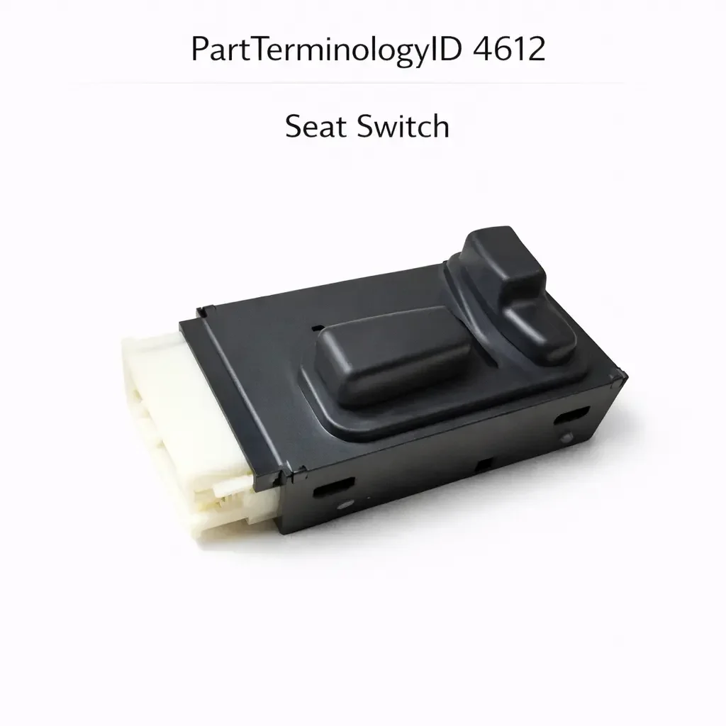
Seat Switch (PartTerminologyID 4612): Motor Circuit Configuration, Axis Control Count, and Memory Seat System Compatibility
Written by Arthur Simitian | PartsAdvisory
Introduction
The seat switch is the control interface for the power seat system, allowing the driver and in many applications the front passenger to adjust seat position along one or more axes of movement. On a basic power seat system the switch controls forward and backward travel and seatback recline. On a full-featured system it controls fore-aft travel, seatback angle, seat height at the front and rear independently, lumbar support position, and headrest height, with some applications adding thigh extension and side bolster adjustment. On vehicles with memory seat systems the switch also interfaces with the memory module to trigger stored position recall and to save new positions.
The seat switch is one of the more complex switch assemblies in the vehicle interior because it combines multiple independent motor control circuits in a single housing, uses a variety of joystick, rocker, and button configurations depending on the platform, and on modern vehicles communicates with a seat control module rather than directly wiring the seat motors. When it fails, the most common complaint is one or more axes of movement that no longer respond, which can be caused by the switch, the motor for that axis, the wiring, or the seat control module. Accurate diagnosis requires understanding how the switch fits into the overall seat system architecture.
This guide covers the full picture for PartTerminologyID 4612: switch function, design variations, failure modes, diagnostic approach, and the cataloging attributes that prevent returns.
What the Seat Switch Does
The seat switch sends commands to the seat motor circuit or seat control module for each axis of adjustment the seat provides. Each button press or joystick movement produces a specific electrical signal that the receiving circuit interprets as a command to run the corresponding motor in a specific direction.
Direct Motor Control Systems
On older and simpler power seat systems the switch connects directly to the seat motors through a relay or through the switch contacts themselves. The switch supplies battery voltage or ground to the motor terminals in the appropriate polarity to run the motor in the forward or reverse direction. Each axis of movement has a dedicated contact set within the switch, and the switch must carry the motor current directly.
Motor current for seat adjustment motors typically ranges from 5 to 20 amperes depending on the motor size and the mechanical load. The switch contacts must be rated for this current. A switch with undersized contacts will arc on motor start, causing premature contact wear and eventual contact welding. A welded contact in the motor circuit will run the motor continuously in one direction until the motor reaches a mechanical stop, potentially stripping the drive mechanism or burning out the motor winding.
Seat Control Module Systems
On modern vehicles the seat switch sends low-current signals to a seat control module, which then commands the motors through its own output drivers. The switch carries only signal current, and the module handles the motor power circuit. In this architecture the switch contacts are not required to carry motor current and are accordingly smaller and lower-rated than direct motor control contacts.
The signal format varies by platform. Some systems use a simple switched ground input per motor direction. Others use a resistor matrix or voltage divider that produces a unique voltage level for each switch position on a shared signal wire. Others communicate over a LIN bus or a proprietary serial bus. The replacement switch must match the signal format of the original for the seat control module to interpret the commands correctly.
Memory Seat Interface
On vehicles with memory seat systems the seat switch assembly includes dedicated memory function buttons, typically numbered position buttons and a save button, that interface with the memory seat module. When a memory position is recalled, the module commands the seat motors to move to the stored position. When a new position is saved, the module records the current sensor feedback from each motor axis as the stored target.
The memory seat buttons in the switch assembly are not interchangeable with the position adjustment controls. They communicate with the memory module through a separate circuit or bus channel. A replacement switch that does not include the memory seat contacts or does not include the correct memory bus interface will leave the memory function inoperative even if all position adjustment functions work correctly.
Design and Construction
Joystick Designs
Many power seat switches use a joystick actuator for the primary fore-aft and seatback adjustment functions. The joystick pivots on a ball joint and actuates different contact sets depending on the direction it is pushed. A single joystick can control two or more axes of movement by using diagonal actuation to combine two motor commands. The joystick design reduces the number of physical controls on the switch panel while maintaining intuitive directional correspondence between the control and the seat movement.
Joystick switches are subject to wear at the pivot and at the detent mechanism that provides tactile feedback at the center neutral position. A worn pivot allows the joystick to rest slightly off-center, which can produce a partial contact closure that commands a slow motor movement the driver may not notice until the seat reaches a limit stop.
Rocker Switch Arrays
Some seat switch assemblies use separate rocker switches for each axis of adjustment rather than a joystick. Each rocker controls one axis in two directions. Rocker arrays are common on vehicles where the seat has a large number of independently adjustable functions, because a rocker for each function is more intuitive than a joystick with multiple diagonal positions.
Integrated Switch Panels
On many current vehicles the seat switch is part of an integrated door panel or seat side panel assembly that also includes window switches, mirror controls, and in some cases lumbar and massage controls. The seat adjustment function cannot always be serviced independently of the panel assembly. Confirm whether the seat switch is available as a standalone component or only as part of the full panel before ordering.
Heating and Ventilation Integration
On vehicles with heated or ventilated seats, the seat switch assembly frequently includes the seat heating or ventilation controls in the same housing as the position adjustment controls. A replacement switch that covers the position adjustment function but not the heating or ventilation function will leave those circuits without a control input. Confirm whether the original switch includes heating or ventilation controls before selecting a replacement.
Common Failure Modes
Contact Wear on High-Use Axes
The fore-aft axis is adjusted most frequently and its contact set wears faster than those for other axes. On high-mileage vehicles or fleet vehicles where the seat position is adjusted frequently, the fore-aft contacts develop increased resistance before other axis contacts show any degradation. The symptom is a fore-aft movement that becomes intermittent or requires multiple attempts before responding, while all other axes continue to work normally.
Joystick Pivot Wear and Drift
As the joystick pivot wears, the neutral position tolerance increases and the joystick may rest in a position that produces a partial contact closure. This causes the corresponding motor to run slowly or intermittently without driver input, eventually moving the seat to a limit stop and holding it there. The symptom is a seat that moves on its own, which is typically reported as a motor or module fault before the switch is identified as the source.
Liquid Contamination
The seat switch is located in an area of the vehicle where drink spills are common. Liquid entering the switch housing deposits contaminants on the contact surfaces and can cause contact corrosion, contact bridging from dried residue, or housing warping from liquid absorption. Switches contaminated by sugary drinks often produce intermittent function that worsens over time as the residue hardens and increases contact resistance.
Memory Button Failure
The memory seat buttons within the switch assembly are smaller and less robustly constructed than the position adjustment controls on most platforms. They receive less physical stress than the position controls but are more susceptible to contamination because they are recessed and can trap debris. A failed memory button produces a specific complaint: the driver cannot recall or save a memory position but all seat movement functions work correctly.
Connector Terminal Damage
Seat switch connectors on door-mounted switch panels are subject to the same door harness flexing and connector seal degradation as door lock switches. On seat-side mounted switches the connector is less subject to flexing but may be vulnerable to contamination from spills that reach behind the seat cushion trim.
Symptoms of a Failing Seat Switch
One Axis Does Not Respond
A single axis that does not respond to switch input while all other axes work normally points to either the contact set for that axis within the switch or the motor for that axis. Distinguish between the two by testing the motor directly with battery voltage applied to its terminals. If the motor runs when powered directly but not from the switch, the switch contact for that axis has failed.
All Axes Fail to Respond
If all seat adjustment axes fail simultaneously the fault is more likely in the power supply to the switch, the common ground circuit, the seat control module, or a blown fuse than in the switch itself. Check the fuse for the seat circuit first. If the fuse is intact, confirm power and ground at the switch connector before condemning the switch.
Seat Moves Without Input
Uncommanded seat movement, where the seat moves in a direction without the driver pressing any switch control, points to a stuck or drifting switch contact. A joystick resting off-center due to pivot wear is the most common cause on joystick-style switches. A contact welded in the closed position from arcing is less common but produces the same symptom.
Memory Function Does Not Work
If position adjustment functions normally but memory recall or save does not work, the fault is isolated to the memory button circuit or the memory module. Test the memory button contacts first before investigating the memory module.
Diagnostic Process
Step One: Check the Fuse
Before any other testing, verify the fuse for the power seat circuit is intact. A blown fuse will disable all seat functions simultaneously and can be caused by a motor overload or a wiring short rather than a switch fault. If the fuse is blown, identify and correct the cause before replacing the fuse and retesting.
Step Two: Confirm Power and Ground at the Switch
With the fuse confirmed intact, measure battery voltage at the switch power supply terminal and confirm a good ground at the ground terminal. Absent power or ground at the switch connector points to a wiring fault upstream of the switch.
Step Three: Test Individual Axes
With a multimeter set to continuity or resistance, test each contact set within the switch in both actuation directions. For resistor-coded switches, measure the resistance value for each position and compare to specification. Any contact set that does not produce the expected result confirms a switch fault for that axis.
Step Four: Test the Motors Directly
For any axis that does not respond to switch input, test the corresponding motor by applying battery voltage directly to the motor connector terminals in both polarities. A motor that runs correctly when powered directly but not from the switch confirms the switch contact for that axis has failed.
Step Five: Scan for Module Faults
On systems with a seat control module, scan for DTCs in the module before and after switch replacement. Module codes referencing switch input circuits confirm the switch as the fault source. Module codes referencing motor output circuits or motor current faults point to the motor or its wiring.
Cataloging Attributes: What to Confirm Before Listing
These are the attributes most commonly missing or incorrect in catalog listings for PartTerminologyID 4612 and the most likely to cause a return if omitted.
Number of adjustment axes: State the number of independently controlled axes the switch covers. A six-way switch covering fore-aft, seatback, and height is not interchangeable with an eight-way switch that adds independent front and rear height control, even if both physically mount in the same location.
Circuit architecture: State whether the switch is for a direct motor control system or a seat control module signal input system. This distinction determines the contact current rating, the signal format, and the connector pinout. A direct motor control switch installed in a seat control module system will produce incorrect signal levels and may damage the module input circuit.
Memory seat compatibility: State explicitly whether the switch includes memory seat controls and whether the memory interface is a direct switched circuit or a bus-connected interface. A switch without memory controls installed in a memory seat application leaves the memory function without a control input.
Heating and ventilation integration: State whether the switch includes seat heating or ventilation controls. This is frequently omitted from listings, producing returns from buyers whose vehicle has heated seats and whose new switch has no heating control.
Driver versus passenger designation: State explicitly whether the switch is for the driver's seat or the front passenger seat. On many platforms the driver's switch includes memory seat controls that are absent from the passenger switch. Installing a passenger switch in the driver's position removes the memory function.
Connector pin count and body type: State the pin count. Seat switches can have connectors ranging from 6 pins on a basic four-way system to 20 or more pins on a full-featured memory seat system with heating and ventilation integration. An incorrect pin count is immediately obvious on installation but wastes the buyer's time and generates a return.
Common Cataloging Mistakes
The most common mistake is listing seat switches by axis count alone without specifying circuit architecture. A six-way seat switch for a direct motor control system has a fundamentally different internal design than a six-way switch for a seat control module system, even if both are described as six-way switches covering the same vehicle. This distinction must be in the listing.
The second most common mistake is omitting heated seat integration from the listing. On platforms where heated seats are a common option, a significant portion of buyers have the heated seat option. A listing that does not state whether the switch includes or excludes heated seat controls will generate returns from heated seat buyers who receive a switch without the heating controls they need.
The third mistake is treating driver and passenger seat switches as interchangeable on platforms where the driver switch includes memory controls. The physical appearance may be nearly identical on some platforms, and a catalog entry that does not distinguish between driver and passenger applications will route passenger switches to buyers who need the driver switch with memory capability.
Installation Overview
Seat switch replacement is generally straightforward but requires care with the connector and trim components.
Accessing the Switch
On door-panel-mounted seat switches, the switch bezel or the full door panel section containing the switch must be removed. Most bezels clip into the door panel and can be released with a trim tool. On vehicles where the seat switch is integrated into the full door switch panel, the entire panel must be removed as described in the door panel disassembly procedure for the specific vehicle.
On seat-side-mounted switches, the switch is typically accessible by removing the seat side trim panel. This usually involves unclipping a plastic trim cover from the seat frame and disconnecting the switch connector from behind. On some applications a single screw retains the switch in its mounting bracket in addition to the trim clips.
Connector Handling
Seat switch connectors on door-panel applications may be difficult to reach once the panel is partially removed. Do not force the connector release tab; use a small flat tool to depress the tab while pulling the connector body straight back. Damaged connector release tabs on seat switch connectors are a common result of rushed disassembly.
On seat-side applications, confirm the connector is fully seated after installation by pressing it firmly until the retention tab clicks. A partially seated connector on a seat switch produces intermittent function that can be mistaken for a faulty new switch.
Post-Installation Check
After installation, test all axes of movement through the full range of travel in both directions before reassembling the trim. Confirm memory functions if applicable. On seat control module systems, connect a scan tool and confirm no new DTCs are present. Clear any codes that were set during the diagnostic process and confirm they do not return after several complete seat adjustment cycles.
Related Components and Systems
Seat Adjustment Motors
Each axis of seat movement is driven by a dedicated electric motor. On a six-way seat there are typically three motors: one for fore-aft, one for seatback recline, and one for height. On an eight-way seat there are four or more motors. Each motor connects to the switch or seat control module through a dedicated wiring circuit. When an axis fails to respond, testing the motor directly by applying battery voltage to its terminals is the fastest way to determine whether the fault is in the switch or the motor. A motor that runs correctly when powered directly but not from the switch confirms a switch contact fault. A motor that does not run when powered directly confirms a motor fault regardless of switch condition.
Seat Control Module
On modern vehicles with a seat control module, the module is the intermediary between the switch and the motors. It receives switch input signals, processes them, and commands the motors through its own output drivers. The module also monitors motor current to detect stall conditions and limit switch inputs to prevent the seat from moving beyond its mechanical limits. A failed seat control module output driver will prevent one or more axes from responding to switch input even when the switch and motors are functioning correctly. Scan tool bidirectional control of the individual motors through the seat control module is the most efficient way to isolate a fault to the switch input circuit versus the module output circuit.
Memory Seat Module
On vehicles with a memory seat system, a dedicated memory module or a memory function integrated into the seat control module stores position data for each axis and commands the motors to move to stored positions when a memory recall is triggered. The memory module receives its position data from sensors on each motor axis, typically Hall effect sensors or potentiometers that report the current axis position as a voltage or pulse count. If the memory recall function produces incorrect positioning, the fault may be in the position sensors rather than the switch or module. Confirming that switch inputs and module commands are correct before investigating the position sensors keeps the diagnosis efficient.
Lumbar Support Actuator
On vehicles with power lumbar support, the lumbar adjustment function is often integrated into the seat switch assembly. The lumbar actuator is typically a small air pump and valve assembly or a small electric motor that adjusts the lumbar bladder pressure or the lumbar support plate position. A seat switch that includes lumbar controls but is replaced with one that omits them will leave the lumbar function without a control input. Confirm lumbar integration in the switch specification before ordering.
Seat Heating Element and Thermostat
On vehicles with heated seats, the seat heating control integrated into the seat switch typically commands a relay or a heating control module that manages current to the seat heating element. The heating element itself is a resistive mat embedded in the seat cushion and seatback. A failed heating element will produce a no-heat complaint even when the switch and control module are functioning correctly. When diagnosing a heated seat complaint on a vehicle where the switch has just been replaced, confirm element resistance before attributing the fault to the new switch.
Frequently Asked Questions
Why does only one direction of one axis stop working?
A single direction failure on a single axis, where the seat moves in one direction on that axis but not the other, points specifically to one contact set within the switch for that axis. Each direction of movement uses a separate contact set. When one contact set fails while the other remains functional, the result is a seat that moves in one direction only. This is a reliable indicator of a switch fault rather than a motor fault, because a failed motor would affect both directions of that axis equally.
Can I repair a seat switch rather than replacing it?
On some switch designs the contact surfaces are accessible after disassembly of the switch housing. Light oxidation on contact surfaces can sometimes be removed with electrical contact cleaner, restoring function temporarily. However, worn contact surfaces cannot be restored by cleaning and will fail again quickly. Liquid-contaminated switches with corrosion on contact surfaces or internal components typically require replacement rather than repair. Repair is practical only as a temporary measure when the replacement part is on order.
My seat creeps forward slowly on its own. Is the switch the cause?
Uncommanded slow movement in one direction is consistent with a partially closed contact set in the switch, which is supplying low current to the motor continuously. On joystick switches this is most commonly caused by a worn pivot that allows the joystick to rest in a slight forward position rather than returning to true center. Test by disconnecting the switch connector with the vehicle on and powered. If the uncommanded movement stops immediately after disconnection, the switch is confirmed as the source.
Does the seat switch need to be programmed after replacement?
On most applications the seat switch requires no programming. It is a passive input device. The exception is memory seat switches on platforms where the memory module must be initialized to recognize a new switch address on a LIN or CAN bus. On these platforms the initialization procedure is typically a simple key cycle or a button sequence performed through the BCM or seat control module, not a dealer-level programming event. Confirm whether initialization is required for the specific application before installation.
Will a seat switch from a higher trim level work on a base trim vehicle?
Only if the circuit architecture and connector are identical and the seat control module on the base vehicle is calibrated to accept the additional axis inputs from the higher-trim switch. In practice, installing a higher-trim switch on a base vehicle usually results in the additional functions being ignored by the module, and in some cases the module may generate a fault code for an unexpected input. Installing a lower-trim switch on a higher-trim vehicle will leave the axes not present on the lower-trim switch non-functional. Trim level substitution is not recommended and is not a supported fitment.
How do I identify which axis contact has failed without a service manual?
With the switch disconnected from the vehicle, use a multimeter in continuity mode and systematically test each terminal pair while actuating each switch position in both directions. Most seat switches use a logical terminal assignment where adjacent terminals correspond to the same motor circuit. Working through all terminal combinations in each switch position will map which contacts close for which input, allowing identification of a contact set that does not change state when the corresponding switch position is actuated.
Status in New Databases
PIES/PCdb: PartTerminologyID 4612, Seat Switch
PIES 8.0 / PCdb 2.0: No change in PartTerminologyID or terminology label
Summary
The seat switch is a multi-axis motor control interface whose return rate is driven by omitted attributes in catalog listings rather than by part quality. The number of adjustment axes, circuit architecture, memory seat compatibility, heated seat integration, and driver versus passenger designation are the attributes that determine whether the replacement restores full seat function. A listing that omits any of these attributes will generate returns from buyers whose vehicle has the non-default configuration for that attribute.
PartTerminologyID 4612, Seat Switch, covers a wide range of switch designs from basic four-way direct motor control assemblies to fully integrated eight-way memory seat panels with heating and ventilation controls on a seat control module bus. Correct cataloging requires stating all relevant attributes explicitly for every listing, without assuming that year, make, model, and seating position are sufficient to identify the correct switch.