Engine Oil Temperature Switch (PartTerminologyID 4592): Activation Threshold Calibration, Contact Configuration, and Engine Protection Circuit Compatibility
Written by Arthur Simitian | PartsAdvisory
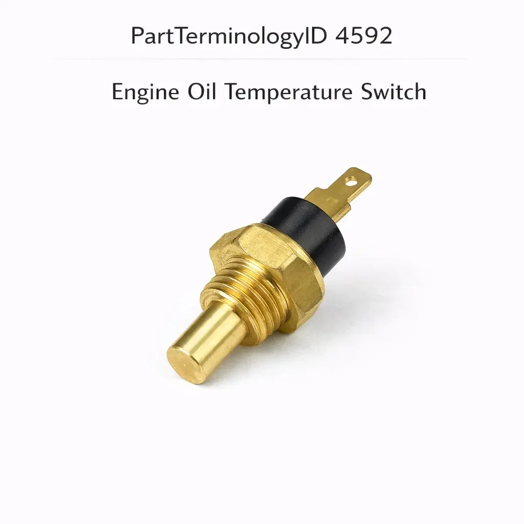
PartTerminologyID 4592, Engine Oil Temperature Switch, is the thermostatic switch threaded into the engine oil gallery, oil pan, or oil filter housing that monitors oil temperature and opens or closes an electrical contact at a calibrated threshold to activate an oil temperature warning lamp, signal the ECU or engine management system that oil temperature has exceeded the safe operating maximum, activate an oil cooler bypass valve, or in some applications disable the engine's oil temperature-sensitive performance maps when oil temperature is outside the designed operating range. That definition covers the oil temperature monitoring and circuit switching function correctly and leaves unresolved every question that determines whether the replacement switch's temperature threshold matches the original calibration for the specific engine's maximum safe oil operating temperature and the circuit it controls, whether the switch is a normally open type that closes on temperature rise or a normally closed type that opens on temperature rise depending on the circuit design, whether the switch provides a single on-off warning contact or an analog temperature output for continuous oil temperature monitoring, whether the thread specification and sealing method match the installation port, whether the switch sensing element response time is appropriate for the specific application's thermal protection requirement, and whether the switch is compatible with the ECU's oil temperature input signal type on vehicles where the ECU uses oil temperature data for engine management decisions including warm-up fueling enrichment, variable valve timing calibration, and transmission shift scheduling on applications where the engine oil temperature sensor is shared with the transmission control system.
It does not specify the temperature threshold, contact configuration, output type, thread specification, response time, or ECU signal compatibility. A listing under PartTerminologyID 4592 that states only year, make, and model without threshold and contact configuration cannot be evaluated by a technician replacing a failed oil temperature switch on a turbocharged performance application where the original switch activated the oil temperature warning at 135 degrees Celsius and the replacement activates at 150 degrees Celsius, allowing the engine to operate between 135 and 150 degrees Celsius without warning while the turbocharger bearings sustain accelerated thermal degradation in the temperature window the original switch was designed to flag as a cooling system intervention requirement.
For sellers, PartTerminologyID 4592 occupies a distinct position from PartTerminologyID 4588 (Engine Oil Pressure Switch) in the engine protection circuit category: where the oil pressure switch monitors the mechanical lubrication delivery function and its failure immediately threatens bearing surfaces, the oil temperature switch monitors the thermal condition of the lubricant itself and its failure allows sustained high-temperature operation that degrades oil viscosity, accelerates oxidation of the oil chemistry, and thermally stresses the turbocharger bearing housings and piston cooling jets that depend on oil temperature remaining within the designed operating band. The threshold calibration for the oil temperature switch is as safety-critical as the pressure switch threshold and must be stated in every listing without exception.
What the Engine Oil Temperature Switch Does
Oil Temperature Warning Circuit and the Thermal Protection Threshold
The oil temperature warning switch monitors the engine oil's thermal state and activates a warning circuit when the oil temperature exceeds the threshold that indicates the oil is approaching or has reached a condition where its viscosity, film strength, or oxidation stability is compromised. Unlike coolant temperature, which typically stabilizes at a consistent thermostat-governed operating temperature, engine oil temperature varies widely with driving conditions: oil temperature at steady highway cruise may be 100 to 110 degrees Celsius, while oil temperature during sustained high-load performance driving or towing in hot ambient conditions can reach 130 to 150 degrees Celsius, with track and motorsport use regularly reaching 150 to 170 degrees Celsius.
The warning threshold is calibrated to the specific engine and oil specification's thermal limit. Engines using conventional 5W-30 oil set the warning threshold at approximately 130 to 140 degrees Celsius because conventional oil begins to oxidize and lose viscosity rapidly above this range. Engines using synthetic 5W-50 or 10W-60 oil tolerate higher operating temperatures and may set the warning threshold at 150 to 160 degrees Celsius. Turbocharged engines have a lower threshold than naturally aspirated engines of similar displacement because the turbocharger bearings are directly cooled by the engine oil and excessive oil temperature produces coking deposits in the turbocharger's center section bearing housing.
A replacement switch with a threshold 15 degrees above the original allows the engine to operate between the two thresholds without warning. In a turbocharged application operating regularly above the original threshold during aggressive driving, this represents sustained high-temperature operation that deposits coke in the turbocharger bearing housing over multiple heat cycles, gradually restricting the bearing oil supply and accelerating turbocharger bearing wear. The coke deposits accumulate silently with no warning indication until the turbocharger bearing clearance increases enough to produce audible noise or visible oil consumption.
Contact Configuration and the Warning Circuit Logic
The oil temperature switch's contact configuration determines whether the warning circuit activates at high temperature or is suppressed at high temperature, following the same normally open and normally closed conventions described across adjacent thermal switch PartTerminologyIDs throughout this series.
For a high-temperature warning circuit, the switch is typically a normally open type that closes when temperature exceeds the threshold, completing the warning lamp ground circuit through the switch contact and illuminating the warning lamp. A normally closed switch in the same circuit would illuminate the warning lamp continuously at all temperatures below the threshold (which is the normal operating range) and extinguish it above the threshold, which is exactly opposite to the intended behavior.
For a temperature-gated enable circuit (where the switch enables an engine management function such as oil cooler bypass activation or a performance map unlock when oil temperature is above a minimum), the switch is typically a normally open type that closes above the minimum temperature threshold, completing the enable circuit. For a temperature-gated disable circuit (where the switch disables a function when temperature is above the maximum), the normally closed convention is appropriate.
The contact configuration must be confirmed against the specific circuit the switch controls, not assumed from the general application description. An oil temperature switch controlling a warning lamp in one vehicle may be normally open while the same PartTerminologyID controlling an oil cooler bypass valve in another vehicle may be normally closed, and both are correctly cataloged under PartTerminologyID 4592.
Analog Oil Temperature Output and ECU Integration
On vehicles where the ECU manages engine operation based on oil temperature data, the oil temperature switch may provide a continuous analog temperature signal rather than a simple binary contact closure. The analog output allows the ECU to make graduated management decisions across the full oil temperature range rather than a single threshold response.
ECU functions governed by analog oil temperature input include warm-up enrichment calibration (the ECU maintains a slightly richer mixture at cold oil temperatures when cold-start enrichment must be sustained longer than coolant temperature alone indicates), variable valve timing maps (some engines use oil temperature rather than coolant temperature to govern the cam timing advance strategy during warm-up because oil temperature more accurately represents the engine's internal thermal state for lubrication circuit response), knock threshold adjustment (some ECU calibrations advance the knock threshold at lower oil temperatures when bearing clearances are tighter from thermal contraction), and turbocharger wastegate duty cycle adjustment (some turbocharged applications reduce boost pressure at high oil temperatures to reduce turbocharger bearing thermal load).
A replacement switch with a different analog output characteristic than the original will cause the ECU to miscalculate oil temperature across the full operating range, applying incorrect warm-up enrichment, incorrect VVT maps, and incorrect boost management. The error magnitude depends on the difference between the replacement's and the original's resistance-temperature or voltage-temperature curves, but the consequences include elevated fuel consumption at cold oil temperatures (from excessive warm-up enrichment) and elevated turbocharger stress at high oil temperatures (from inadequate boost reduction).
Installation Position and the Oil Gallery Temperature Representation
The oil temperature switch is installed at one of several positions depending on the specific engine and what temperature the switch is designed to represent. Oil sump or oil pan installation measures the bulk temperature of the oil in the reservoir, which is the coolest oil in the system because it has returned from the bearings and cooled in the pan before being recirculated. Oil gallery installation (at the main gallery or at the outlet of the oil pump) measures the temperature of the oil being delivered to the bearings, which is the relevant temperature for bearing protection decisions. Oil filter housing installation measures the temperature of oil entering the filter, which is intermediate between the gallery and sump temperatures.
A replacement switch installed at the correct port but designed for a different installation position's temperature range will produce incorrect threshold behavior because the temperature at the installation point may be 15 to 30 degrees Celsius different from the temperature at the position the switch was calibrated for. A switch calibrated for gallery temperature installed at a sump position will activate its warning threshold at a sump temperature that corresponds to a gallery temperature significantly above the original warning threshold, delaying the warning response.
Why This Part Generates Returns
Buyers return engine oil temperature switches because the threshold is 150 degrees Celsius where the original was 135 degrees Celsius, allowing the turbocharger to sustain coke deposit accumulation during the 15-degree operating window above the original threshold; the contact configuration is normally closed and the warning circuit requires normally open, causing the warning lamp to illuminate at all temperatures below the threshold during every drive and extinguish when the engine overheats; the thread is M12 x 1.5 and the engine port uses M14 x 1.5, producing a partial thread engagement that leaks oil at the first heat cycle; the analog resistance output at 100 degrees Celsius differs by 30 ohms from the original, causing the ECU to apply warm-up enrichment for 6 additional minutes of every cold-start drive; the switch is calibrated for gallery installation and is installed at the sump position where the oil temperature runs 20 degrees cooler, causing the warning to activate 20 degrees later than intended relative to actual bearing oil temperature; and the switch response time is 45 seconds where the original was 8 seconds, allowing the oil temperature to spike above the threshold and return before the switch activates, missing brief but dangerous overtemperature events during track use.
Top Return Scenarios
Scenario 1: "Threshold 15 degrees too high, turbocharger coke deposits accumulate in unwarned temperature window"
The replacement switch activates at 150 degrees Celsius. The original activated at 135 degrees. During aggressive motorway driving in summer, the oil temperature regularly reaches 138 to 145 degrees Celsius before the driver reduces speed in response to the original switch's warning. The replacement switch does not activate in this range, and the driver continues at the pace that produces 138 to 145 degree oil temperature without intervention. Over six months, coke deposits accumulate in the turbocharger center section bearing housing as repeated exposure to oil temperatures above 135 degrees produces oxidation and thermal degradation at the bearing surfaces.
Prevention language: "Temperature activation threshold: [X] degrees Celsius. The warning lamp activates when oil temperature exceeds this value. Verify the threshold against the original switch specification. For turbocharged engines, the original threshold is typically set conservatively to prevent coking at the turbocharger bearings. A threshold higher than the original allows sustained operation in the temperature window between the two thresholds without warning, accumulating thermal degradation that manifests progressively over months."
Scenario 2: "Normally closed in normally open warning circuit, warning lamp on at all normal temperatures"
The buyer installs the replacement switch. Immediately after connecting the switch, the oil temperature warning lamp illuminates. After starting and warming the engine, the warning lamp remains on. On a long drive, the warning lamp extinguishes momentarily during the hottest part of the drive and reilluminates as the engine cools slightly. The normally closed contact is closed at all temperatures below the threshold (normal operating range), completing the warning lamp ground circuit permanently during normal operation.
Prevention language: "Contact configuration: [normally open, closes above threshold / normally closed, opens above threshold]. For a standard high-temperature warning circuit, the switch must be normally open below the threshold and close above it. A normally closed switch in a normally open warning circuit illuminates the warning lamp continuously during all normal operating temperatures and extinguishes it at overtemperature, providing exactly opposite indication from the intended circuit behavior."
Scenario 3: "Analog resistance curve offset by 30 ohms, ECU extends warm-up enrichment by 6 minutes"
The buyer installs the replacement combination warning and analog output switch. The warning lamp function is correct. During the first week of use, the owner notices notably higher fuel consumption on short cold-start trips compared to before the replacement. The replacement's resistance-temperature curve produces a reading 30 ohms lower than the original at 100 degrees Celsius oil temperature. The ECU interprets this as a lower oil temperature than actual and continues applying warm-up enrichment for approximately 6 additional minutes per cold start before the analog signal reaches the threshold indicating sufficient warm-up completion.
Prevention language: "Analog resistance output: [resistance at key temperature points, X ohms at 20 degrees C, X ohms at 80 degrees C, X ohms at 120 degrees C]. Verify the resistance-temperature curve against the original switch specification. An analog output offset from the original produces systematic ECU temperature miscalculation across the full operating range, affecting warm-up fueling, VVT maps, and any other ECU strategy governed by oil temperature input."
Scenario 4: "Switch response time 45 seconds versus original 8 seconds, brief overtemperature events missed during track use"
The buyer replaces the oil temperature switch on a track car. During a track session, data logging shows the oil temperature spiking to 155 degrees Celsius for 12 to 18 seconds on sustained high-speed corners before recovering as the straightaway cooling effect reduces temperature. The original switch with an 8-second response time activated the warning during these spikes, prompting the driver to cool down on the straight. The replacement switch with a 45-second response time has not yet reached its activation threshold by the time the temperature recovers, and the warning never activates. After 40 minutes of track use, the oil shows significant darkening and oxidation from repeated brief overtemperature events that were individually below the replacement switch's response time but collectively degraded the oil chemistry.
Prevention language: "Thermal response time: [X] seconds to threshold activation after temperature reaches rated threshold. Verify the response time against the application's thermal rate of change. In track and motorsport applications where oil temperature spikes are brief and rapid, a slow-response switch will not activate the warning during transient overtemperature events that are individually short but cumulatively damaging."
Scenario 5: "Gallery-calibrated switch installed at sump position, warning 20 degrees late relative to bearing oil temperature"
The buyer installs the replacement switch at the oil sump port. The replacement was calibrated for gallery installation where the oil temperature is consistently 20 degrees warmer than the sump. The switch activates at 135 degrees Celsius, which corresponds to a gallery temperature of approximately 155 degrees Celsius (20 degrees above the sump reading at threshold). The bearings have been receiving oil at 155 degrees Celsius for the duration of the sump temperature rising from 135 to the threshold, an overtemperature condition that persists undetected throughout.
Prevention language: "Installation position calibration: [gallery / oil pan sump / filter housing]. Verify the switch's calibration position against the intended installation port. Gallery oil temperature and sump oil temperature differ by 15 to 25 degrees Celsius on most engines. A gallery-calibrated switch installed at the sump position will activate its warning threshold at a sump temperature corresponding to a gallery temperature 15 to 25 degrees above the designed warning level."
Core Listing Attributes for PartTerminologyID 4592
PartTerminologyID: 4592
Component: Engine Oil Temperature Switch
Temperature activation threshold in degrees Celsius (mandatory, in title)
Contact configuration: normally open or normally closed (mandatory, in title)
Output type: binary warning contact only, or combination warning and analog output (mandatory)
Analog resistance-temperature curve for combination types: resistance values at key temperature points (mandatory)
Thread specification: diameter, pitch, and thread form (mandatory)
Sealing method: crush washer, O-ring, or NPT thread sealant (mandatory)
Thermal response time in seconds (mandatory for motorsport and performance applications)
Installation position calibration: gallery, sump, or filter housing (mandatory)
ECU signal compatibility for analog output types (mandatory)
Maximum operating temperature rating in degrees Celsius (mandatory)
Terminal count and function mapping (mandatory)
Year/make/model/engine
Note for turbocharged applications with lower threshold due to turbocharger coking risk
Note for synthetic oil applications with elevated threshold tolerance
Note for ECU analog input applications requiring specific resistance-temperature curve match
Catalog Checklist for ACES/PIES Teams
PartTerminologyID = 4592
Require temperature threshold in title (mandatory)
Require contact configuration in title (mandatory)
Require output type: binary contact or combination (mandatory)
Require analog resistance-temperature curve for combination types (mandatory)
Require thread specification with thread form (mandatory)
Require installation position calibration (mandatory)
Require thermal response time for motorsport and performance applications (mandatory)
Prevent threshold omission: a threshold above the original allows sustained operation in the damaging temperature window without warning; threshold is a safety specification and must be in the title for every listing
Prevent contact configuration omission: a normally closed switch in a normally open circuit illuminates the warning lamp during all normal operation and extinguishes it at overtemperature; configuration must be stated and confirmed
Prevent analog curve omission: a combination switch with an incorrect resistance curve produces ECU warm-up enrichment and VVT calibration errors; the full resistance-temperature curve must be stated for combination types
Prevent installation position omission: a gallery-calibrated switch at the sump position activates warning 15 to 25 degrees late relative to bearing oil temperature; calibration position must be confirmed against the intended installation port
Prevent response time omission on motorsport applications: a slow-response switch misses brief transient overtemperature events during track use; response time must be stated for performance and motorsport applications
Relationship to PartTerminologyID 4588 (Engine Oil Pressure Switch): the oil pressure switch monitors lubrication delivery; the oil temperature switch monitors lubricant thermal condition; both are in the engine lubrication monitoring system but for different fault conditions; the same installation port may host either type on different engine configurations
Differentiate from Engine Coolant Temperature Switch (if cataloged): the coolant temperature switch monitors the engine's cooling water system; the oil temperature switch monitors the lubricant thermal state; both produce warning lamp activations but for different engine systems requiring different diagnostic approaches
FAQ (Buyer Language)
How does the oil temperature switch differ from the coolant temperature switch?
The coolant temperature switch monitors the temperature of the engine's cooling water circuit, which governs the thermostat, cooling fan, and overall engine thermal management. The oil temperature switch monitors the temperature of the engine oil specifically, which determines the oil's viscosity, film strength, and suitability for bearing lubrication. The two circuits protect different systems and use different thresholds calibrated to each fluid's thermal limits. A vehicle may have both, and each must be replaced with a switch calibrated for its specific fluid's properties.
Why does my oil temperature warning lamp illuminate immediately after I replace the switch?
An oil temperature warning lamp that illuminates immediately after switch installation before the engine has warmed indicates a normally closed switch has been installed in a circuit requiring normally open. The normally closed contact is closed at all temperatures below the activation threshold, which includes all temperatures during the first minutes of a cold start. Confirm the contact configuration of the replacement switch against the original specification. The replacement must be normally open (contact open at temperatures below threshold) for a standard high-temperature warning circuit.
My engine uses full synthetic 5W-50 oil. Does the threshold change?
The original threshold calibration is set for the specific oil specification approved for the engine by the manufacturer. If the engine is approved for both synthetic and conventional oil and the original switch was calibrated for the conventional oil's thermal limit, using synthetic oil with a higher thermal tolerance does not mean a higher-threshold replacement is appropriate. The switch threshold should match the original specification regardless of the oil type currently in the engine, because the original threshold was set to flag a condition requiring driver intervention for that engine and its turbocharger system, not solely for the oil's thermal limit.
How do I measure the analog resistance-temperature output of the original switch before replacing it?
Remove the original switch and place its sensing tip in a container of water heated to measured temperatures using a calibrated thermometer. At each temperature, measure the resistance across the switch terminals using a multimeter in ohms mode. Record the resistance at ambient temperature, 40 degrees Celsius, 80 degrees Celsius, and 100 degrees Celsius. Compare these readings to the replacement switch's published resistance-temperature table. If the replacement's readings differ by more than 10 ohms at any measured point, the ECU will miscalculate oil temperature at that operating condition.
Related PartTerminologyIDs
Engine Oil Pressure Switch (PartTerminologyID 4588): monitors oil pressure rather than oil temperature; a falling oil pressure warning and a rising oil temperature warning occurring simultaneously indicate the same underlying cause (oil breakdown from thermal degradation reducing viscosity and oil film thickness); both switches protect the engine lubrication system but from different fault directions
Engine Coolant Temperature Switch (PartTerminologyID 4312 or similar): monitors the engine cooling water temperature; high coolant temperature and high oil temperature are often related (an overheating engine also overheats the oil through conduction) but each switch is calibrated to its specific fluid's thermal limits and the two cannot substitute for each other
Turbocharger Oil Feed Line (if cataloged): the supply line delivering oil to the turbocharger bearings; a correctly functioning oil temperature switch that activates frequently during normal operation confirms a cooling system or oil cooling capacity issue rather than a switch fault; address the underlying thermal cause before replacing the switch repeatedly
Status in New Databases
PIES/PCdb: PartTerminologyID 4592, Engine Oil Temperature Switch
PIES 8.0 / PCdb 2.0: No change in PartTerminologyID or terminology label
Final Take for PartTerminologyID 4592
Engine Oil Temperature Switch (PartTerminologyID 4592) is the lubrication thermal monitoring PartTerminologyID where the activation threshold and the contact configuration together define the exact thermal boundary at which the engine's lubrication protective response begins, and a threshold set 15 degrees above the original silently permits sustained bearing oil temperatures in the degradation window that accumulate as turbocharger coke deposits and oil chemistry breakdown over months of driving before the damage becomes detectable. The contact configuration is the attribute with the most immediately visible wrong-direction failure consequence because a normally closed switch in a normally open warning circuit illuminates the warning lamp continuously during safe operation and extinguishes it at overtemperature, providing precisely inverted protection. The analog resistance-temperature curve for combination types is the attribute with the most system-wide calibration consequence because an offset curve corrupts the ECU's oil temperature estimate across the full operating range, affecting warm-up enrichment, VVT calibration, and boost management simultaneously.
State the temperature threshold in the title. State the contact configuration in the title. State the output type. State the analog resistance-temperature curve for combination types. State the thread specification. State the installation position calibration. State the thermal response time for performance applications. For PartTerminologyID 4592, activation threshold, contact configuration, and analog resistance-temperature curve are the three attributes that prevent the three most consequential return scenarios in the engine oil temperature switch buyer population.