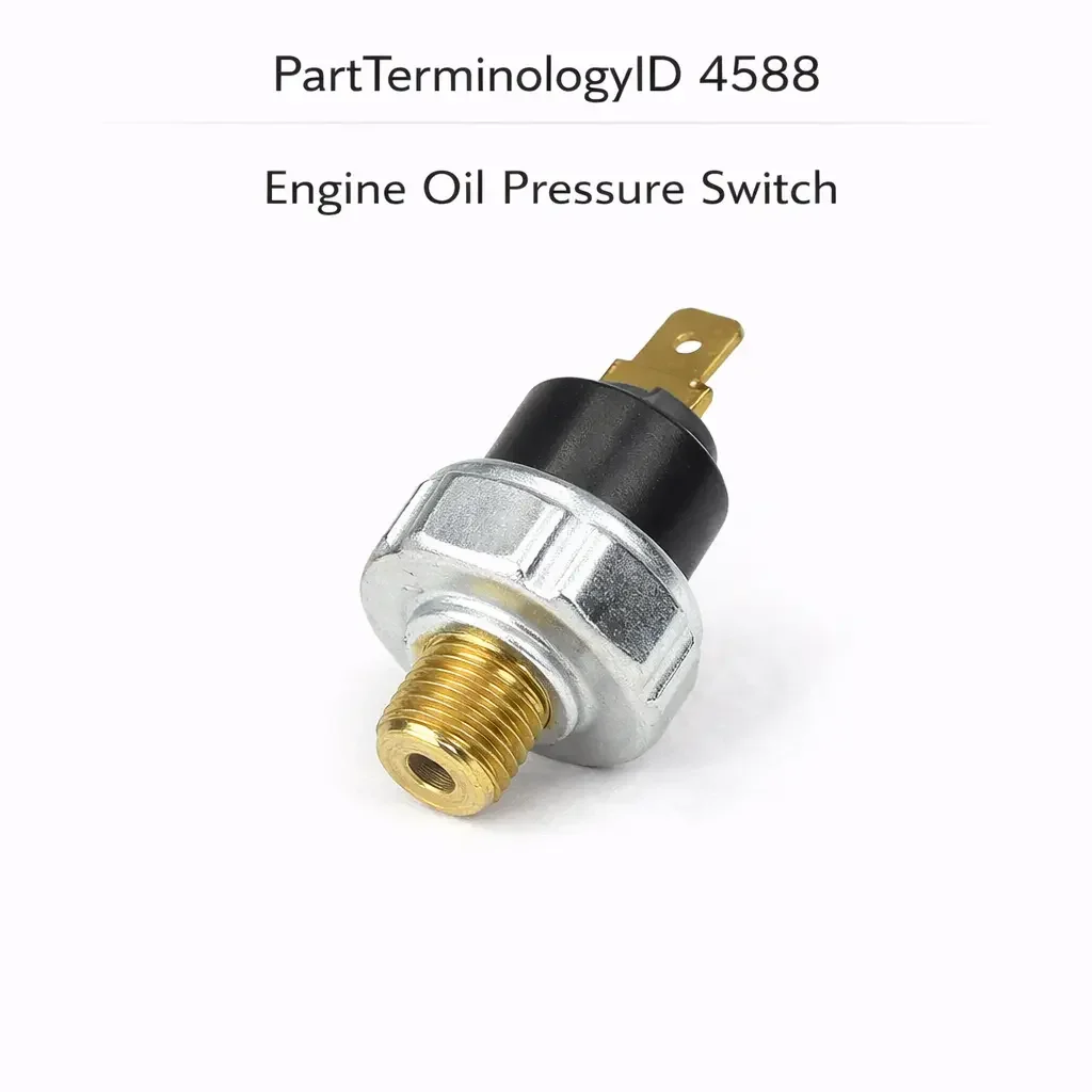
Engine Oil Pressure Switch (PartTerminologyID 4588): Activation Threshold Calibration, Signal Architecture, and Engine Protection Circuit Compatibility
Written by Arthur Simitian | PartsAdvisory
PartTerminologyID 4588, Engine Oil Pressure Switch, is the pressure-sensing switch threaded into the engine lubrication system that monitors the oil pressure at the main gallery or the oil filter housing and opens or closes an electrical contact at a calibrated pressure threshold to activate the oil pressure warning lamp in the instrument cluster, to signal the ECU or engine management system that oil pressure is below the minimum required for safe continued engine operation, and in some applications to disable the fuel pump or shut down the engine when oil pressure falls below the critical threshold, while in other applications simultaneously providing an analog pressure signal to the instrument cluster's oil pressure gauge or to the ECU for continuous oil pressure monitoring beyond the simple low-pressure warning function. That definition covers the oil pressure warning, engine protection, and pressure monitoring functions correctly and leaves unresolved every question that determines whether the replacement switch's activation threshold matches the original calibration for the specific engine's minimum safe operating pressure and normal idle pressure range, whether the switch is a simple two-terminal warning lamp type producing a binary contact closure at threshold or a combination type that provides both the warning lamp contact and a continuous analog pressure signal on separate circuits, whether the switch thread specification matches the engine block or oil filter housing port, whether the switch is a normally closed type that grounds the warning lamp circuit at low pressure or a normally open type depending on the circuit design, whether the replacement is compatible with the ECU's oil pressure input signal type on vehicles where the ECU monitors oil pressure for engine protection and torque management, whether the switch includes a fuel pump safety shutoff output used on some domestic applications to cut fuel pump power when oil pressure is absent during cranking, and whether the switch body's maximum pressure rating covers the engine's peak oil pressure during cold starts when oil viscosity is highest and the pump relief valve may not yet have opened.
It does not specify the activation threshold, switch type, analog output characteristics, thread specification, contact configuration, ECU signal compatibility, fuel pump safety output, or maximum pressure rating. A listing under PartTerminologyID 4588 that states only year, make, and model without activation threshold and switch type cannot be evaluated by a technician replacing a failed oil pressure switch on a high-performance turbocharged application where the original switch activated the warning lamp at 7 psi and the replacement activates at 4 psi, allowing the engine to run at dangerously low pressure between 4 and 7 psi without warning lamp activation and without the ECU receiving the low-pressure signal that would have reduced engine load or initiated a shutdown sequence, producing sustained bearing surface damage from oil starvation during the pressure window the original switch was designed to flag.
For sellers, PartTerminologyID 4588 is the engine lubrication system PartTerminologyID where the activation threshold is a safety-critical specification rather than a performance preference, because the threshold defines the boundary between safe and unsafe engine operation and a threshold set too low allows the engine to operate in the oil starvation zone without the protection the owner believes is present. The switch type (warning lamp only versus combination warning and analog gauge) is the specification with the most visible functional consequence, because a warning lamp-only replacement in a combination application removes the continuous oil pressure gauge reading from the instrument cluster while the warning lamp function appears correct, leaving the driver without the graduated pressure information that indicates developing lubrication system problems before they become critical.
What the Engine Oil Pressure Switch Does
Oil Pressure Warning Lamp Function and the Threshold Calibration Safety Requirement
The oil pressure warning lamp switch monitors the engine's main gallery oil pressure and activates the instrument cluster warning lamp when pressure falls below the calibrated threshold. The warning lamp is the driver's primary alert that lubrication system pressure is insufficient for safe engine operation, and the threshold at which the lamp activates determines how much margin exists between the warning and the engine bearing damage that occurs when oil pressure is zero or near zero.
The activation threshold for the oil pressure warning switch is calibrated to the specific engine's minimum safe operating pressure. This value depends on the engine's bearing clearances, oil pump output characteristics, oil viscosity specification, and the minimum pressure required to maintain hydrodynamic lubrication at the crankshaft and connecting rod bearings under load. For most passenger car gasoline engines, the warning threshold is set between 4 and 7 psi, below which the hydrodynamic oil film at the main bearings begins to break down. For high-performance and turbocharged engines with tighter bearing clearances and higher thermal loads, the threshold may be set at 7 to 15 psi. For diesel engines with longer bearing surfaces and higher combustion pressures, the threshold may be 10 to 20 psi.
A replacement switch with a threshold below the original allows the engine to operate at the dangerously low pressure region between the two thresholds without warning, potentially for extended periods during which the bearing surfaces are sustaining damage from inadequate hydrodynamic lubrication. The damage accumulation in this pressure window is not immediately apparent from the engine's external behavior (it continues to run and develop power normally) and may not manifest as a detectable symptom until significant bearing wear has occurred. The threshold must match the original, and a listing that does not state the threshold is functionally incomplete for this PartTerminologyID.
Normally Closed versus Normally Open Contact Configuration
The oil pressure warning lamp switch is almost universally a normally closed type in the low-pressure warning lamp circuit: the switch contacts are closed (grounding the warning lamp circuit) when oil pressure is below the threshold, which illuminates the warning lamp. When oil pressure rises above the threshold during and after engine startup, the switch opens its contacts, removing the ground from the warning lamp circuit and extinguishing the lamp.
This normally closed at low pressure logic produces the fail-safe behavior: if the switch fails with its contacts stuck closed (the most common mechanical failure mode), the warning lamp remains illuminated even when oil pressure is normal, which the driver interprets as a persistent warning lamp fault and investigates before driving. If the switch fails with contacts stuck open, the warning lamp never illuminates even when oil pressure is critically low, which is the more dangerous failure mode. The normally closed design is preferred precisely because the stuck-closed failure mode produces a false positive warning (driver investigates) rather than a false negative (driver is unaware of oil starvation).
A normally open switch installed in a normally closed warning lamp circuit will illuminate the warning lamp continuously at all times regardless of oil pressure, because the normally open contact is open at low pressure rather than closed. While this appears to be the same fail-safe behavior as a stuck-closed normally closed switch, it is not: a normally open switch provides no oil pressure warning capability at all because the contact opens and closes opposite to what the circuit requires. The warning lamp is always on with normal pressure and would stay on (for a different reason) with low pressure, but the driver cannot distinguish between the two states.
Combination Warning Lamp and Analog Gauge Types
On vehicles equipped with an oil pressure gauge in the instrument cluster rather than (or in addition to) a simple warning lamp, the oil pressure switch is commonly a combination type that provides both the binary warning lamp contact at threshold and a continuous analog pressure signal for the gauge. The combination switch houses two independent sensing elements in a single switch body: the bimetallic disc or diaphragm-and-contact mechanism for the warning lamp function, and a variable resistance pressure transducer (typically 10 to 180 ohms across the engine's operating pressure range for domestic gauges, or alternative resistance ranges for import applications) for the gauge signal.
The combination type uses a three-terminal connector: one terminal for the warning lamp circuit ground output, one terminal for the analog gauge signal output, and one common ground reference terminal. A two-terminal replacement that covers only the warning lamp function will leave the gauge signal circuit unconnected after installation, causing the oil pressure gauge to read at the maximum deflection position (floating at the gauge's full-scale resistance) or at zero deflection (gauge open circuit) depending on the gauge's behavior at an unconnected signal input. The driver notices the gauge is no longer reading correctly immediately, and the absence of graduated pressure information removes the early warning of developing oil system problems that the gauge provided.
The replacement switch type must match the original (warning lamp only, combination warning and gauge, or pure pressure sensor without warning lamp contact) and the analog signal output specification (resistance range, voltage range, or current output) must match the instrument cluster gauge's input calibration.
Fuel Pump Safety Shutoff Circuit Integration
On some domestic applications, primarily Ford vehicles from the late 1970s through the late 1990s, the oil pressure switch is wired into the fuel pump circuit as a safety shutoff. In this architecture, the oil pressure switch provides one of two paths through which the fuel pump receives power: the normal path through the fuel pump relay (which is active when the ignition switch is in the run position and the relay is energized) and the oil pressure safety path (which is active when the oil pressure switch contact is closed, indicating that the engine has developed oil pressure and the fuel pump should continue running even if the fuel pump relay fails). When the engine is cranking but has not yet started, the oil pressure switch contact is open because no oil pressure has been developed, and the fuel pump receives power only from the relay. Once the engine starts and develops oil pressure, the oil pressure switch contact closes and provides the second power path to the fuel pump.
The practical consequence of this architecture is that the oil pressure switch on these applications has a dedicated fuel pump output terminal in addition to the warning lamp terminal, and the replacement switch must include this output to maintain the fuel pump safety circuit. A replacement that covers only the warning lamp function will not include the fuel pump output terminal, leaving the fuel pump safety circuit permanently open. On a vehicle where the fuel pump relay subsequently fails, the fuel pump will lose power and the engine will stall even though the engine is running and has adequate oil pressure, because the safety circuit that was designed to maintain fuel pump power independently of the relay is absent.
Maximum Pressure Rating and the Cold Start Spike Requirement
The oil pressure switch body and sensing element must be rated for the maximum transient oil pressure the engine can produce. During cold starts with thick high-viscosity oil before the engine reaches operating temperature, the oil pump may produce pressures significantly above the normal operating range before the pump relief valve opens. Engines using 0W-20 or 5W-30 oil at operating temperature may produce 80 to 120 psi cold-start peak pressures despite normal operating pressure of 25 to 65 psi. Engines using heavier viscosity oils in cold climates can produce transient pressures above 150 psi during the first seconds of a cold start.
A switch rated for the normal operating pressure maximum but not the cold-start transient will rupture the diaphragm or unseat the sensing element during the first cold start in winter conditions, releasing engine oil at the switch body and producing a rapid oil loss that may not be noticed until the warning lamp activates from the subsequent low pressure caused by the oil loss itself.
The maximum pressure rating must exceed the engine's cold-start transient pressure peak, which is typically 1.5 to 2 times the normal maximum operating pressure. The maximum pressure rating must be stated for every oil pressure switch listing as a safety specification rather than a performance attribute.
Thread Specification, Sealing Method, and Oil Loss Risk
Thread form and pitch identification in the engine block
The oil pressure switch installs in a threaded port in the engine block, typically at the main gallery near the oil filter housing or at a dedicated sender port on the side of the block. The thread specification is engine-specific and varies between domestic and import applications. Common thread specifications include 1/8-27 NPT on domestic applications, M12 x 1.5 metric on many European and Japanese applications, M14 x 1.5 on some diesel and performance applications, and 3/8-18 NPT on some larger displacement domestic V8 applications.
An incorrect thread specification at an engine oil port is an oil leak risk because engine oil at operating pressure (up to 65 psi) and operating temperature will force itself past any imperfect thread engagement. Even a thread that appears to engage at installation may develop an oil leak as the engine thermal cycles and the partial thread engagement loosens slightly from differential thermal expansion.
The sealing method must also match the port type. NPT tapered thread ports seal through thread interference and require thread sealant (anaerobic thread sealer or PTFE tape) applied to the male thread. Metric straight thread ports use a copper or aluminum crush washer at the thread shoulder for sealing. A straight thread switch in a tapered thread port will not develop a seal through thread interference alone. A tapered thread switch in a straight thread port will not produce a crush washer seal at the shoulder.
ECU Oil Pressure Input and the Engine Management Integration
Pressure input for torque management and protection strategies
On modern engines with full electronic management, the ECU receives the oil pressure signal from a dedicated oil pressure sensor (which provides a continuous analog pressure signal) or from the oil pressure warning switch (which provides a binary low-pressure signal). The ECU uses the oil pressure input for multiple engine management functions: confirming oil pressure during cranking before enabling full fuel injection, reducing engine torque in response to detected low oil pressure to slow the rate of bearing damage before the driver responds to the warning lamp, and in some applications shutting the engine down when pressure drops below the critical threshold during operation.
On vehicles where the ECU receives the oil pressure signal from the same switch that activates the warning lamp, the switch must provide the signal type the ECU expects. If the ECU expects an analog pressure signal and the replacement switch provides only a binary contact at threshold, the ECU will receive an invalid input and may store an oil pressure sensor fault code rather than monitoring actual oil pressure. The torque reduction and engine protection strategies dependent on the analog pressure input will be unavailable.
The ECU's oil pressure input type (analog sensor, binary switch, or combination) must be confirmed from the factory wiring diagram before ordering any oil pressure switch replacement on modern vehicles with electronic engine management.
Why This Part Generates Returns
Buyers return engine oil pressure switches because the activation threshold is 4 psi and the original was 7 psi, allowing the engine to operate between 4 and 7 psi without a warning lamp and enabling bearing damage during extended idle in hot conditions where oil pressure drops to 5 to 6 psi; the replacement is a two-terminal warning lamp type and the original was a three-terminal combination type covering warning lamp and analog gauge, causing the oil pressure gauge to read maximum deflection continuously with no graduated pressure information; the fuel pump output terminal is absent on a Ford application where the oil pressure switch provides the safety fuel pump supply path, causing the engine to stall when the fuel pump relay fails because the safety supply path is missing; the thread is M14 x 1.5 and the engine block port is 1/8-27 NPT, producing a partial thread engagement that leaks oil at operating pressure within 24 hours of installation; the switch body is rated for 80 psi maximum and the engine produces 120 psi cold-start transient pressure, rupturing the diaphragm on the first winter cold start and releasing oil at the switch body; the analog resistance output range is 10 to 180 ohms and the original gauge circuit uses a 0 to 90 ohm range, causing the oil pressure gauge to read maximum deflection at idle and off-scale above idle; the contact configuration is normally open and the warning lamp circuit requires normally closed, causing the warning lamp to remain permanently illuminated at all oil pressure levels; and the replacement is a single-circuit warning lamp type without ECU analog input and the vehicle's ECU requires a continuous analog pressure signal for torque management, storing an oil pressure sensor fault and disabling the ECU's oil pressure-dependent protection strategy.
Top Return Scenarios
Scenario 1: "4 psi threshold in 7 psi application, engine operates in starvation zone without warning"
The replacement switch activates at 4 psi. The original activated at 7 psi. The engine routinely idles at 5 to 6 psi on hot summer days when oil viscosity is reduced from extended operation and the engine idle speed is low. The replacement switch does not activate the warning lamp at these pressures because they are above its 4 psi threshold. The engine operates with inadequate hydrodynamic lubrication at the main bearings for extended periods during hot idle, accumulating bearing surface damage. A rod knock appears six months later that is attributed to oil starvation but the switch threshold discrepancy is not identified until the engine is disassembled.
Prevention language: "Activation threshold: [X] psi. The warning lamp activates when oil pressure drops below this value. Verify the threshold against the original switch specification and the engine's minimum safe operating pressure. A threshold set below the original allows the engine to operate in the oil starvation pressure zone without warning activation. For high-performance and turbocharged engines, confirm the threshold against the engine builder's or manufacturer's minimum pressure specification."
Scenario 2: "Two-terminal switch in three-terminal combination application, oil pressure gauge reads maximum continuously"
The buyer installs the replacement two-terminal warning lamp switch. The warning lamp extinguishes correctly after startup. The oil pressure gauge in the instrument cluster deflects immediately to the maximum reading position and remains there regardless of actual oil pressure. The gauge signal terminal from the original three-terminal combination switch is unconnected in the replacement. The gauge circuit's input floats at the supply voltage without the variable resistance load the sender provided, causing the gauge to deflect full-scale.
Prevention language: "Switch type: [warning lamp only, two terminals / combination warning lamp and analog gauge signal, three terminals]. Connector terminal count: [X]. Verify the switch type against the original. A two-terminal replacement in a three-terminal combination application leaves the gauge signal circuit unconnected. The oil pressure gauge will read full-scale or zero depending on the gauge circuit's behavior at an open signal input."
Scenario 3: "Fuel pump output absent, engine stalls when fuel pump relay fails, oil safety path missing"
The buyer installs the replacement switch on a Ford application with an oil pressure-actuated fuel pump safety circuit. Three months later, the fuel pump relay fails. The engine begins stalling at idle and on deceleration because the fuel pump loses power when the relay opens. The oil pressure safety path that would have maintained fuel pump power through the switch contact when the relay fails is absent in the replacement switch. The driver is stranded and the repair requires both a new fuel pump relay and a replacement oil pressure switch with the fuel pump output terminal.
Prevention language: "Fuel pump safety output terminal: [included at terminal [X] / not included]. On applicable Ford applications, the oil pressure switch provides a parallel fuel pump power supply path through a dedicated output terminal that maintains fuel pump operation when the primary fuel pump relay fails. A replacement without this terminal permanently removes the fuel pump safety circuit, leaving the vehicle dependent entirely on the fuel pump relay for fuel delivery."
Scenario 4: "M14 thread in 1/8-27 NPT port, oil leak within 24 hours of installation"
The buyer installs the replacement switch. All functions operate correctly immediately after installation. The following morning, the owner discovers a puddle of oil beneath the engine. The M14 x 1.5 metric thread engages partially in the 1/8-27 NPT tapered port before the thread forms diverge. Engine oil at operating pressure forces past the partial thread engagement at the first heat cycle, producing a weep that worsens as the threads wear from differential thermal expansion.
Prevention language: "Thread specification: [diameter x pitch, thread form: NPT tapered / metric straight with copper washer]. Verify thread specification using a thread gauge at the engine block port before installation. An M14 metric switch in a 1/8-27 NPT port will not develop an oil-tight seal at any torque. Engine oil released at the switch body under operating pressure produces rapid oil loss that may not activate the low-pressure warning before significant engine damage has occurred."
Scenario 5: "Switch rated 80 psi, cold-start transient 120 psi, diaphragm ruptures on first winter cold start"
The buyer installs the replacement switch on a vehicle in a northern climate. The switch body is rated for 80 psi maximum. During the first cold start at minus 15 degrees Celsius with 5W-30 oil that has become viscous overnight, the oil pump produces a 120 psi transient before the relief valve opens. The switch diaphragm, rated for 80 psi, ruptures under the 120 psi transient. Engine oil is released at the switch body position immediately after the cold start, producing rapid oil loss that activates the warning lamp within 30 seconds of startup.
Prevention language: "Maximum pressure rating: [X] psi. Verify the maximum pressure rating against the engine's cold-start transient oil pressure, which can reach 1.5 to 2 times the normal maximum operating pressure when using full-viscosity oil at cold ambient temperatures. A switch rated only for the normal operating pressure maximum will fail during the first cold-weather start when viscous oil produces peak pump pressures above the switch's rated maximum."
Scenario 6: "Analog resistance range 10 to 180 ohms, gauge calibrated for 0 to 90 ohm range, gauge reads incorrectly at all pressures"
The buyer installs the replacement combination switch. The warning lamp function is correct. The oil pressure gauge reads significantly above the normal range at all engine operating conditions. At idle where the original switch produced approximately 25 ohms (corresponding to low idle pressure on the 0 to 90 ohm scale), the replacement switch produces approximately 45 ohms on its 10 to 180 ohm scale for the same pressure. The gauge, calibrated for 0 to 90 ohms, reads the 45-ohm input as approximately mid-scale rather than low idle pressure.
Prevention language: "Analog signal output range: [minimum X ohms to maximum X ohms] / [minimum X volts to maximum X volts]. Verify the analog output range against the instrument cluster gauge's input calibration. A replacement with a different resistance range than the original produces systematic gauge reading errors at all pressure levels. The gauge will read incorrectly throughout the operating range, not just at one pressure point."
Scenario 7: "Normally open switch in normally closed warning lamp circuit, lamp permanently illuminated"
The buyer installs the replacement normally open switch. Immediately after installation with the engine off and no oil pressure, the warning lamp illuminates (correct appearance). After starting the engine and building oil pressure, the warning lamp remains illuminated instead of extinguishing. The normally open contact opens at the low pressure start condition and closes above the threshold, which is the opposite of what the warning lamp circuit requires for correct operation.
Prevention language: "Contact configuration: [normally closed at low pressure, opens above threshold / normally open at low pressure, closes above threshold]. Verify the contact configuration against the warning lamp circuit design. On virtually all standard oil pressure warning circuits, the switch must be normally closed (lamp on) at low pressure and open (lamp off) above the threshold. A normally open switch provides no usable warning function in the standard circuit."
Scenario 8: "Warning lamp-only switch missing ECU analog input, torque management and protection strategy disabled"
The buyer installs the replacement warning lamp-only switch on a modern direct-injected engine where the ECU expects an analog pressure signal for torque management and pre-shutdown oil pressure monitoring. The ECU receives no analog signal from the replacement, stores an oil pressure sensor input fault, and disables the oil pressure-dependent torque reduction strategy. Three months later, during a track day event where oil pressure drops due to oil surge under cornering loads, the ECU does not reduce torque in response to the developing low-pressure condition, and the engine sustains bearing damage before the warning lamp activates.
Prevention language: "ECU analog signal output: [included, continuous analog pressure signal for ECU input / not included, warning lamp contact only]. Verify whether the ECU requires an analog oil pressure input for engine management functions including torque reduction on low-pressure detection. A warning lamp-only switch in an ECU analog input application removes the ECU's pressure-dependent protection strategies, leaving only the binary warning lamp as the sole low-pressure alert."
Core Listing Attributes for PartTerminologyID 4588
PartTerminologyID: 4588
Component: Engine Oil Pressure Switch
Activation threshold in psi and bar (mandatory, in title)
Switch type: warning lamp only, combination warning and analog gauge, or analog sensor without warning lamp contact (mandatory, in title)
Contact configuration: normally closed at low pressure (mandatory)
Analog signal output range for combination and sensor types: resistance range in ohms or voltage range (mandatory)
Thread specification: diameter, pitch, and thread form (mandatory)
Sealing method: NPT thread sealant, crush washer, or O-ring (mandatory)
Maximum pressure rating in psi (mandatory)
Fuel pump safety output: included with terminal identification, or not included (mandatory for applicable applications)
ECU analog input compatibility: signal type and range for ECU input where applicable (mandatory)
Terminal count and function mapping (mandatory)
Hex body size in mm (mandatory)
Year/make/model/engine
Note for high-performance and turbocharged engines with elevated minimum pressure thresholds
Note for Ford applications with fuel pump safety circuit
Note for applications where ECU requires analog oil pressure input for engine management
Note for cold-climate applications requiring elevated maximum pressure rating
Catalog Checklist for ACES/PIES Teams
PartTerminologyID = 4588
Require activation threshold in psi and bar in title (mandatory)
Require switch type in title: warning lamp only, combination, or analog sensor (mandatory)
Require contact configuration: normally closed at low pressure (mandatory)
Require analog output range for combination and sensor types (mandatory)
Require thread specification with thread form (mandatory)
Require maximum pressure rating (mandatory)
Require fuel pump safety output status for applicable Ford applications (mandatory)
Require ECU analog signal compatibility for applicable applications (mandatory)
Require terminal count with function mapping (mandatory)
Prevent threshold omission: a threshold below the original allows operation in the oil starvation zone without warning; threshold is a safety specification and must be in the title for every listing without exception
Prevent switch type omission: a two-terminal switch in a three-terminal combination application leaves the gauge signal circuit permanently unconnected; type must be confirmed and stated
Prevent fuel pump output omission: absent fuel pump output on Ford applications removes the safety fuel pump supply path and produces a stall on fuel pump relay failure; fuel pump terminal status must be confirmed for all applicable applications
Prevent analog range omission: a combination switch with an incorrect resistance range produces systematic gauge reading errors at all pressures; output range must be stated and verified against the gauge calibration
Prevent maximum pressure omission: a switch rated below the cold-start transient fails at the switch body and releases engine oil; maximum pressure must exceed the cold-start peak
Prevent ECU analog input omission: a warning lamp-only switch in an ECU analog input application disables torque management and oil pressure-dependent protection strategies; ECU input compatibility must be confirmed for all modern electronically managed engines
Prevent contact configuration omission: a normally open switch in a normally closed warning lamp circuit provides no usable warning function; contact configuration must be confirmed as normally closed at low pressure for all standard warning lamp applications
Differentiate from Engine Oil Pressure Sensor (if cataloged separately): on some modern applications the oil pressure monitoring function is split between a simple warning switch and a dedicated analog pressure sensor; the switch activates the warning lamp at threshold while the sensor provides continuous ECU input; both are in the lubrication system circuit but at different positions for different functions; confirm which component requires replacement before ordering
Differentiate from Oil Level Sensor (if cataloged): the oil level sensor monitors oil quantity in the sump; the oil pressure switch monitors the pressurized oil delivery to the engine bearings; both can activate a warning lamp but for different fault conditions requiring different diagnostic approaches
FAQ (Buyer Language)
How do I confirm the correct activation threshold for my engine?
The activation threshold is listed in the factory service manual under the engine lubrication system specifications. For most domestic passenger car gasoline engines, the threshold is between 4 and 7 psi. For diesel engines and high-performance applications, the threshold is typically higher, between 10 and 20 psi. The original switch part number cross-reference is the most reliable confirmation method. Do not substitute a threshold based on a general engine family specification without confirming it for the specific engine model and year.
My oil pressure gauge reads full-scale after replacing the oil pressure switch. What happened?
An oil pressure gauge reading maximum deflection after switch replacement is the characteristic symptom of a two-terminal warning lamp switch installed in a three-terminal combination application. The gauge signal terminal of the original combination switch is unconnected in the replacement, and the gauge circuit's input floats at the supply voltage without a variable resistance load. The gauge deflects to maximum because it interprets the open circuit as a very low resistance (maximum pressure) reading. Confirm the replacement switch's terminal count against the original connector.
Can I use a universal oil pressure switch if the thread size matches?
Only if the activation threshold, switch type, analog output range, contact configuration, maximum pressure rating, and fuel pump output (where applicable) all also match the original specification. A universal switch with the correct thread size but an incorrect threshold or incorrect type will produce incorrect warning lamp behavior or gauge readings as described throughout this post. Confirm every specification independently, not just the thread size.
My oil pressure warning lamp stays on after engine startup. Is the switch bad?
An oil pressure warning lamp that remains on after engine startup can indicate either a failed switch stuck in the closed position, actual low oil pressure, or a normally open switch installed in a normally closed circuit. First confirm actual oil pressure with a mechanical gauge at the sending unit port. If the mechanical gauge shows normal pressure, the warning lamp circuit has a fault. If the switch tests as stuck closed (contact closed when removed from the engine and tested without pressure applied), the switch has failed and requires replacement. If the switch tests as open with no pressure applied, a normally open switch has been installed in a circuit requiring normally closed.
Does my vehicle with an oil pressure gauge need a different switch than one with only a warning lamp?
Yes. A vehicle with an oil pressure gauge in the instrument cluster requires either a combination warning lamp and analog gauge switch or a separate dedicated pressure sender for the gauge alongside a standalone warning switch. Installing a warning lamp-only switch removes the gauge signal entirely, and the gauge will deflect to full-scale or to zero depending on the circuit's behavior at an unconnected input. Confirm the original switch's terminal count and function before ordering a replacement.
Related PartTerminologyIDs
Engine Oil Pressure Sensor (if cataloged separately): the dedicated analog pressure transducer providing continuous ECU input on applications where the ECU pressure input is separate from the warning lamp switch; both monitor oil pressure but through different output types for different circuit functions; confirm which component is in the failed circuit before ordering
Oil Pressure Gauge (if cataloged): the instrument cluster gauge that receives the combination switch's analog output; a gauge that reads full-scale after switch replacement confirms an unconnected gauge signal terminal rather than a failed gauge; verify the switch type and terminal count before replacing the gauge
Fuel Pump Relay (if cataloged): the primary fuel pump power source on Ford applications with oil pressure-actuated fuel pump safety circuits; a stall event on fuel pump relay failure on these applications confirms a missing fuel pump safety terminal in the replacement switch rather than a relay or pump fault alone
Oil Filter (if cataloged): the filter housing sometimes provides the switch mounting port on some applications; a switch installed at the filter housing mounting port rather than directly in the engine block requires confirmation that the port receives full main gallery pressure rather than filtered or regulated pressure that differs from the main gallery
Status in New Databases
PIES/PCdb: PartTerminologyID 4588, Engine Oil Pressure Switch
PIES 8.0 / PCdb 2.0: No change in PartTerminologyID or terminology label
Final Take for PartTerminologyID 4588
Engine Oil Pressure Switch (PartTerminologyID 4588) is the engine lubrication PartTerminologyID where the activation threshold is a safety-critical specification that must be in the title without exception, because a threshold set below the original allows the engine to operate in the bearing starvation zone without warning activation, accumulating damage that manifests months later as rod knock or bearing failure attributed to an unrelated cause. The switch type is the attribute with the most immediately visible functional consequence because a two-terminal replacement in a three-terminal combination application leaves the oil pressure gauge reading maximum deflection from the moment of installation, which is noticed on the first post-installation engine start. The maximum pressure rating is the attribute with the most catastrophic immediate failure consequence because a switch rated below the cold-start transient ruptures and releases engine oil at the switch body on the first cold-weather start.
State the activation threshold in psi and bar in the title. State the switch type in the title. State the contact configuration. State the analog output range for combination types. State the thread specification with thread form. State the maximum pressure rating. State the fuel pump output status for applicable applications. State the ECU analog compatibility for modern applications. For PartTerminologyID 4588, activation threshold, switch type, and maximum pressure rating are the three attributes that prevent the three most consequential and most frequently overlooked return scenarios in the engine oil pressure switch buyer population.