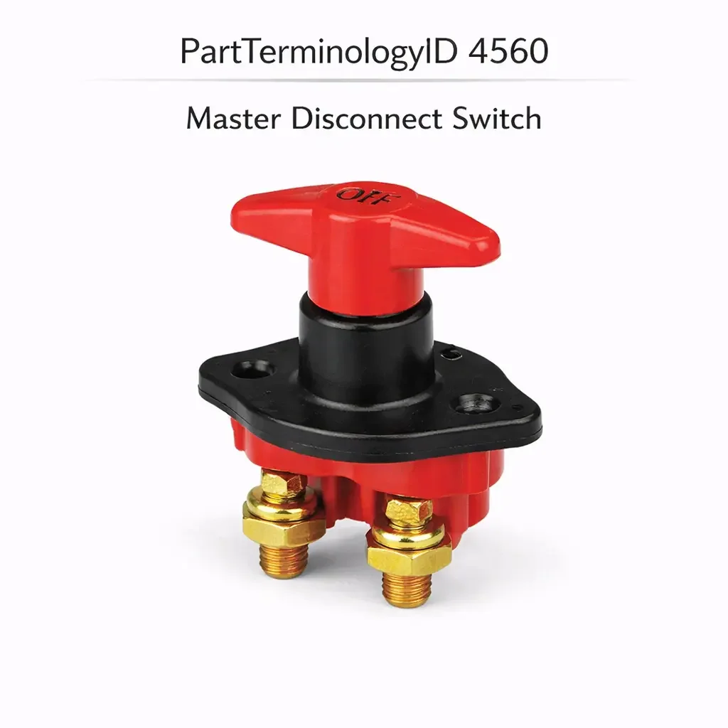
Master Disconnect Switch (PartTerminologyID 4560): Current Rating, Interrupt Capacity, and Electrical System Isolation Architecture
Written by Arthur Simitian | PartsAdvisory
PartTerminologyID 4560, Master Disconnect Switch, is the manually operated switch that isolates the vehicle's entire electrical system from the battery by interrupting the main battery positive or negative supply circuit, used in racing vehicles to meet sanctioning body safety requirements for rapid electrical shutdown during fire or accident events, in commercial and fleet vehicles to prevent parasitic battery drain during extended storage or out-of-service periods, in marine and recreational vehicle applications to isolate the house or starter battery banks independently, and in specialty vehicle applications including ambulances, fire apparatus, and military vehicles where complete electrical isolation is required for maintenance safety or operational security. That definition covers the battery isolation and complete electrical disconnect function correctly and leaves unresolved every question that determines whether the replacement switch's continuous current rating covers the vehicle's maximum simultaneous electrical load, whether the switch's interrupt rating covers the maximum current the switch must break at contact opening under the most adverse load condition, whether the switch is a positive-side disconnect type interrupting the battery positive terminal circuit or a negative-side disconnect type interrupting the battery ground return, whether the switch housing and mounting interface match the original installation position on the battery, battery tray, chassis, or bulkhead, whether the switch includes a provision for a master key or locking mechanism to prevent unauthorized reconnection, whether the switch is rated for the system voltage including 12-volt, 24-volt, and 48-volt applications on commercial and hybrid vehicles, and whether the switch includes auxiliary contacts for pre-disconnecting sensitive electronic modules before the main circuit is interrupted to prevent voltage spike damage to ECUs and control modules.
It does not specify the continuous current rating, interrupt rating, circuit polarity position, mounting interface, locking provision, system voltage, or auxiliary contact configuration. A listing under PartTerminologyID 4560 that states only current rating without interrupt rating and system voltage cannot be evaluated by a technician replacing a failed master disconnect switch on a 24-volt commercial diesel where the original switch was rated for 300 amperes continuous and 6,000 amperes interrupt at 24 volts, and the replacement is rated for 300 amperes continuous but only 2,000 amperes interrupt at 12 volts, failing under the 24-volt inductive load interrupt arc that exceeds both the interrupt rating and the voltage rating of the replacement on the first disconnect event under load.
For sellers, PartTerminologyID 4560 is the battery system PartTerminologyID where the interrupt rating is the safety-critical specification that receives the least attention in catalog listings and causes the most consequential installation failures. A switch with an adequate continuous current rating but an inadequate interrupt rating will handle sustained electrical loads correctly but will produce an arc flash when opened under load that either welds the contacts permanently closed or destroys the switch housing, leaving the vehicle's electrical system permanently connected and the safety disconnect function permanently lost. The interrupt rating must always be stated alongside the continuous rating and must be confirmed against both the maximum load current and the system voltage.
What the Master Disconnect Switch Does
Complete Electrical Isolation and the Safety Mandate
The master disconnect switch provides complete electrical isolation of the vehicle's electrical system from the battery in a single switch operation. Unlike a fuse that protects against overcurrent in a specific circuit, the master disconnect interrupts all circuits simultaneously by opening the main battery supply path. Once the switch is opened, no current can flow from the battery to any vehicle circuit regardless of switch positions, shorts, or faults elsewhere in the system.
In racing applications, sanctioning bodies including NASCAR, NHRA, SCCA, and most international motorsport authorities require a master disconnect switch accessible from both inside and outside the vehicle so that corner workers and safety personnel can cut power to a disabled vehicle without requiring the driver to be conscious or accessible. The switch must be clearly marked with the international lightning bolt symbol and must be operable with one hand without requiring tools.
In commercial vehicle applications, the master disconnect prevents parasitic drain from the multiple electronic control modules, telematics systems, and auxiliary loads that draw current continuously even when the vehicle is parked. A commercial vehicle with multiple ECUs, a refrigeration unit, and a telematics module may draw 3 to 5 amperes in the parked state, draining a fully charged battery in 10 to 15 days without a master disconnect.
Continuous Current Rating and the Maximum Simultaneous Load Calculation
The continuous current rating of the master disconnect switch must equal or exceed the vehicle's maximum simultaneous electrical load: the total current that all circuits draw simultaneously at their peak demand. For a racing vehicle with a high-output alternator, a fuel pump, a water pump, an ignition system, and data acquisition electronics, the peak simultaneous load may reach 150 to 250 amperes. For a commercial diesel with multiple ECUs, a refrigeration unit, lighting systems, and auxiliary hydraulics, the peak load may reach 400 to 600 amperes.
The continuous rating is typically stated as a temperature-rated value: a switch rated for 300 amperes at 25 degrees Celsius ambient may be derated to 250 amperes at 50 degrees Celsius because the contact's thermal resistance allows the contact temperature to rise above the maximum at the higher ambient. The installation environment temperature must be considered when selecting a continuous rating, particularly for switches mounted in enclosed battery compartments or engine bays where ambient temperatures can reach 60 to 80 degrees Celsius during operation.
Interrupt Rating and the Arc Energy Consideration
The interrupt rating is the maximum current the switch can safely break at the contact gap when the switch is opened under load. When the switch contacts separate while current is flowing, an arc forms across the gap as the contact separation distance increases. The arc energy is proportional to the current being switched, the system voltage, and the inductance of the circuit being interrupted. High-inductance loads such as motor windings, solenoid coils, and transformer-coupled loads store energy that sustains the arc as the contacts separate.
An under-rated interrupt switch produces an arc that bridges the contact gap continuously rather than extinguishing as the gap widens. A sustained arc at the contact surface melts and fuses the contact material, welding the contacts in the closed position. Once welded, the switch cannot be opened and the safety disconnect function is permanently lost. In a fire scenario where the master disconnect is the primary means of cutting power to prevent electrical ignition of fuel, a welded disconnect switch is a catastrophic safety failure.
The interrupt rating must be stated in kiloamperes (kA) for high-current applications and must be confirmed against the maximum available short-circuit current at the battery terminals, not merely the normal operating current. The maximum short-circuit current at a healthy battery with heavy cable can reach 1,000 to 2,000 amperes on a 12-volt automotive system and 2,000 to 4,000 amperes on a 24-volt commercial system.
System Voltage Rating and the Arc Suppression Requirement
The arc energy at contact separation is directly proportional to the system voltage as well as the current. A switch rated for 12-volt operation uses arc suppression geometry (contact gap distance, arc chute design, and contact material) calibrated for 12-volt arc energy. Installing a 12-volt rated switch in a 24-volt system produces arc energy at the contact gap that is double the switch's designed suppression capacity, potentially sustaining the arc across the contact gap and welding the contacts.
The system voltage (12 volt, 24 volt, or 48 volt on mild hybrid systems) must be confirmed and matched to the switch's voltage rating before any other specification is evaluated. A 12-volt switch with an adequate current rating in a 24-volt system is not a compliant installation regardless of the current rating match.
Auxiliary Pre-Disconnect Contacts and ECU Voltage Spike Protection
When the master disconnect switch opens the main battery circuit under load, the sudden interruption of current in cables and wiring that have measurable inductance produces a voltage spike. The magnitude of the spike is proportional to the inductance of the circuit and the rate of current change at interruption. On a vehicle with long battery cable runs and multiple high-current loads, this spike can reach 50 to 100 volts on a 12-volt system, briefly exceeding the voltage ratings of ECU power supply circuits and transient voltage suppressors.
Some master disconnect switches include auxiliary contacts that open slightly before the main contacts, providing a pre-disconnect signal that allows ECUs and sensitive modules to enter a controlled shutdown state before the main circuit is interrupted. These auxiliary contacts are wired to the ECU's ignition input or a dedicated pre-disconnect input, allowing the module to save its operating state and disable its internal switching circuits before the voltage spike arrives.
A replacement switch without auxiliary pre-disconnect contacts on an application that uses them removes this protection from all connected ECUs and control modules. Each manual disconnect event under load has the potential to expose the ECUs to a voltage spike that may immediately exceed the module's input protection rating or cause cumulative damage over repeated disconnect events.
Top Return Scenarios
Scenario 1: "12-volt interrupt rating in 24-volt application, contacts weld on first disconnect under load"
The replacement switch is rated for 300 amperes continuous and 2,000 amperes interrupt at 12 volts. The vehicle is a 24-volt commercial diesel. On the first disconnect event while the engine is running and charging, the 24-volt arc energy across the contact gap exceeds the switch's 12-volt calibrated arc suppression. The contacts weld in the closed position. The master disconnect switch can no longer isolate the battery.
Prevention language: "System voltage rating: [12 volt / 24 volt / 48 volt]. Interrupt rating at system voltage: [X] kA. Verify the system voltage rating before any other specification. A switch rated for 12-volt operation in a 24-volt system produces arc energy at the contact gap that exceeds the designed suppression capacity, welding the contacts and permanently disabling the disconnect function."
Scenario 2: "Continuous rating adequate but interrupt rating at 1,500 amperes, contacts weld during short-circuit disconnect"
The replacement switch is rated for 400 amperes continuous and 1,500 amperes interrupt. The vehicle experiences a wiring fault that produces a near-short-circuit condition drawing 1,800 amperes from the battery. When the driver attempts to open the master disconnect to isolate the fault, the 1,800-ampere arc exceeds the switch's 1,500-ampere interrupt rating. The contacts weld under the arc energy. The fault current continues flowing through the welded switch.
Prevention language: "Interrupt rating: [X] kA at [X] volts. The interrupt rating must exceed the maximum available short-circuit current at the battery terminals, not only the normal operating current. Verify the interrupt rating against the battery's cold cranking ampere rating, which approximates the maximum available fault current the switch must be capable of safely interrupting."
Scenario 3: "Auxiliary pre-disconnect contacts absent, ECU voltage spike on each manual disconnect"
The buyer replaces the master disconnect with a unit that does not include auxiliary pre-disconnect contacts. On the original switch, the auxiliary contacts signaled the ECU to shut down gracefully before the main contacts opened. With the replacement, each manual disconnect produces a voltage spike of 60 to 80 volts across the ECU power supply input as the main contacts open under the inductive load of the charging circuit. After 15 disconnect events over a racing season, one ECU fails from accumulated transient damage.
Prevention language: "Auxiliary pre-disconnect contacts: [included, opens [X] ms before main contacts / not included]. A replacement without pre-disconnect contacts removes the ECU shutdown signal on each manual disconnect. Inductive load interruption produces a voltage spike proportional to circuit inductance and current rate of change. Sensitive ECUs without pre-disconnect protection accumulate transient damage over repeated disconnect events."
Core Listing Attributes for PartTerminologyID 4560
PartTerminologyID: 4560
Component: Master Disconnect Switch
Continuous current rating in amperes at rated ambient temperature (mandatory, in title)
Interrupt rating in kA at system voltage (mandatory, in title)
System voltage rating: 12 volt, 24 volt, or 48 volt (mandatory, in title)
Circuit polarity: positive side or negative side disconnect (mandatory)
Locking provision: keyed lock, removable handle, or none (mandatory)
Auxiliary pre-disconnect contacts: included with timing specification, or not included (mandatory)
Mounting interface: battery terminal post, chassis bulkhead, or battery tray mount (mandatory)
Terminal stud size and thread specification (mandatory)
Housing material and IP rating for environmental protection (mandatory)
Sanctioning body compliance: list applicable race series approvals where applicable (mandatory for racing applications)
Year/make/model or vehicle type/application category
FAQ (Buyer Language)
Why do I need to know the interrupt rating separately from the continuous rating?
The continuous rating tells you whether the switch can carry the normal electrical load without overheating. The interrupt rating tells you whether the switch can safely open under the maximum possible fault current without the arc welding the contacts. A switch that carries 300 amperes continuously but can only safely interrupt 1,000 amperes will weld its contacts if a 1,500-ampere fault occurs and you try to disconnect. Since the master disconnect is often the last line of defense in a fire or fault emergency, the interrupt rating is the more critical specification for safety purposes.
Should I disconnect the positive or negative battery terminal?
Either interrupts the circuit, but common practice and most sanctioning body requirements specify the positive side for racing applications because it eliminates the risk of accidentally grounding the positive cable during a disconnect event. Commercial vehicle and marine applications sometimes use the negative side for corrosion management reasons. Confirm the original switch's polarity position before ordering and maintain the same polarity in the replacement.
My master disconnect switch is required by my sanctioning body. What certifications should I look for?
Most North American racing sanctioning bodies accept switches meeting FIA 8910 (the international standard for master switches in competition vehicles) or equivalent national standards. Verify the specific sanctioning body's technical regulations for the current season, as approved switch specifications change periodically. The switch must typically be marked with the FIA-approved lightning bolt symbol, be operable from both inside and outside the vehicle, and be accessible without tools.
Related PartTerminologyIDs
Junction Block Switch (PartTerminologyID 4544): covers switching functions within the fuse and relay junction block, including battery disconnect applications at the block level; the master disconnect switch is the primary full-system battery isolation device while the junction block switch may provide secondary or auxiliary circuit switching within the distribution block
Battery (if cataloged): the energy source the master disconnect isolates; the battery's cold cranking ampere rating approximates the maximum available fault current the disconnect switch must be rated to interrupt; confirm the CCA rating alongside the switch's interrupt rating
Status in New Databases
PIES/PCdb: PartTerminologyID 4560, Master Disconnect Switch
PIES 8.0 / PCdb 2.0: No change in PartTerminologyID or terminology label
Final Take for PartTerminologyID 4560
Master Disconnect Switch (PartTerminologyID 4560) is the battery isolation PartTerminologyID where the interrupt rating and the system voltage rating are the two safety specifications that cannot be inferred from the continuous current rating alone, because a switch that carries the normal load correctly will weld its contacts if opened under a fault current exceeding its interrupt rating or if installed in a higher-voltage system than its arc suppression was designed for. Both failures permanently disable the very safety function the switch was installed to provide.
State the continuous current rating in the title. State the interrupt rating in the title. State the system voltage rating in the title. State the circuit polarity position. State the auxiliary pre-disconnect contact status. State the locking provision. For PartTerminologyID 4560, interrupt rating, system voltage rating, and auxiliary pre-disconnect contacts are the three attributes that prevent the three most safety-critical return scenarios in the master disconnect switch buyer population.