Automatic Transmission Lock-Up Torque Converter Switch (PartTerminologyID 4548): Engagement Threshold Calibration, Signal Architecture, and Transmission Control Compatibility
Written by Arthur Simitian | PartsAdvisory
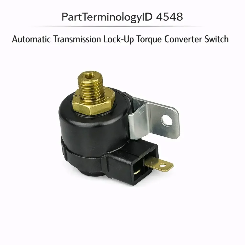
PartTerminologyID 4548, Automatic Transmission Lock-Up Torque Converter Switch, is the switch or sensor that monitors vehicle speed, throttle position, transmission fluid temperature, or manifold vacuum and signals the torque converter lock-up solenoid control circuit or the transmission control module when the operating conditions are appropriate for engaging the torque converter clutch, mechanically coupling the torque converter's pump and turbine to eliminate hydraulic slip and improve fuel efficiency at steady-state cruise conditions, and releasing the clutch when conditions require the torque converter's fluid coupling function to be restored for smooth transmission of engine torque during acceleration, deceleration, or low-speed operation. That definition covers the lock-up engagement command function correctly and leaves unresolved every question that determines whether the replacement switch's engagement threshold calibration matches the original for the specific transmission and engine combination, whether the switch monitors vehicle speed, throttle position, fluid temperature, manifold vacuum, or a combination of these parameters to determine lock-up readiness, whether the switch is a direct solenoid control type that carries the lock-up solenoid current or a signal input type that sends a command to the transmission control module, whether the switch connector and mounting geometry match the original installation position in the transmission housing, valve body, or external mounting bracket, and whether the switch is compatible with the transmission control module's input signal type on vehicles where the module manages lock-up engagement through software rather than through direct switch-to-solenoid activation.
It does not specify the engagement threshold parameters, monitored input type, circuit position, connector specification, mounting geometry, or transmission control module compatibility. A listing under PartTerminologyID 4548 that states only year, make, and model without engagement threshold and monitored parameter type cannot be evaluated by a technician replacing a failed lock-up switch on a vehicle where the original switch engaged the torque converter clutch based on a vehicle speed above 45 mph combined with a throttle position below 60 percent opening, and the replacement engages based on vehicle speed above 45 mph without monitoring throttle position, causing the torque converter to lock up during heavy throttle acceleration events at highway speed where the hydraulic coupling function is needed for smooth power transmission, producing a pronounced shudder and driveline surge every time the throttle is pushed past 60 percent above 45 mph.
For sellers, PartTerminologyID 4548 covers a component whose failure consequences span from reduced fuel economy (lock-up never engaging) to driveline shudder and customer perception of transmission slipping (lock-up engaging at inappropriate conditions), and whose replacement complexity varies from a straightforward external switch swap to a transmission-control-module-dependent calibration. The buyer population is typically a transmission repair shop or an advanced DIY technician who has confirmed lock-up circuit failure through a scan tool or wiring diagram analysis rather than a general buyer who has identified the switch by symptom alone.
What the Automatic Transmission Lock-Up Torque Converter Switch Does
Torque Converter Lock-Up Function and the Efficiency Rationale
The torque converter in an automatic transmission uses hydraulic fluid to transfer engine torque to the transmission input shaft, providing a smooth coupling that absorbs engine torque pulses and allows the engine to idle without stalling when the vehicle is stopped. The hydraulic coupling, however, introduces slip between the converter's pump (driven by the engine) and turbine (driving the transmission input shaft), which generates heat and reduces fuel efficiency at steady-state cruise conditions where the smooth coupling function is not needed.
The torque converter clutch (TCC) eliminates this slip by mechanically coupling the pump and turbine through a friction clutch plate when steady cruise conditions are met. With the TCC engaged, the engine and transmission input shaft turn at exactly the same speed, eliminating the hydraulic slip and improving fuel economy at highway cruise by 1 to 3 mpg on most applications. The TCC is released when the driver accelerates aggressively, brakes, or decelerates to a lower speed where the hydraulic coupling is needed to prevent engine stall or driveline harshness.
The lock-up switch is the component that determines when TCC engagement and release conditions are met and signals the TCC solenoid circuit accordingly.
Engagement Threshold Parameters and Their Interaction
The engagement conditions that must be simultaneously satisfied before the lock-up switch activates the TCC solenoid vary by transmission generation and vehicle application. The most common engagement parameters monitored individually or in combination are vehicle speed above a minimum threshold (ensuring the vehicle is at a stable cruise speed rather than accelerating), throttle position below a maximum threshold (ensuring the driver is not demanding aggressive acceleration), transmission fluid temperature above a minimum threshold (ensuring the fluid has reached operating viscosity for reliable clutch engagement), manifold vacuum above a minimum threshold (on older vacuum-controlled systems, ensuring the engine is at light load rather than high load), and in some applications a brake pedal position switch that releases the TCC when the brake pedal is applied.
A replacement switch that monitors fewer engagement parameters than the original will engage the TCC in operating conditions the original excluded. A switch that monitors vehicle speed only without throttle position will engage the TCC during hard acceleration at speeds above the engagement threshold, causing the driveline shudder and surge described in the opening paragraph. A switch that does not include the brake pedal release input will maintain TCC engagement when the brake pedal is applied, transmitting engine braking through the locked converter to the drivetrain in a manner that produces a jerky deceleration response.
The parameter set monitored by the replacement switch must match the original's engagement logic exactly. Adding parameters produces over-cautious engagement (TCC may never engage if an added parameter is never satisfied). Removing parameters produces inappropriate engagement in conditions the original excluded.
Direct Solenoid Control versus Transmission Control Module Input Architecture
The lock-up switch is positioned in the TCC circuit in one of two fundamental architectures. In the direct solenoid control architecture used on transmissions from the 1970s through the early 1990s, the switch carries the TCC solenoid's operating current directly through its contacts. When the engagement conditions are met, the switch contacts close and energize the solenoid, which hydraulically applies the converter clutch through the transmission valve body. The switch contact must be rated for the solenoid's operating current, typically 0.5 to 2.0 amperes.
In the transmission control module architecture used on modern electronically controlled transmissions, the switch provides one or more input signals to the TCM, which evaluates the inputs alongside other parameters (transmission gear ratio, turbine speed ratio, and TCC slip speed from the wheel speed sensors) and activates the TCC solenoid through a dedicated TCM output. The switch in this architecture carries only the low-current input signal to the TCM and the contact current rating requirement is minimal. The signal type and threshold calibration must match the TCM's input specification.
A direct solenoid switch installed in a TCM input position will present the solenoid current voltage across the TCM's low-current input pin, exceeding the input's rated voltage and potentially damaging the TCM input stage on the first engagement event. A TCM input signal switch installed in a direct solenoid circuit will carry the solenoid current through contacts rated only for signal-level current, welding the contacts on the first engagement and permanently activating the TCC solenoid.
Vacuum-Operated Lock-Up Systems and the Manifold Vacuum Signal
Some older lock-up torque converter systems from the late 1970s and early 1980s used a vacuum switch mounted on the intake manifold to monitor manifold vacuum as the primary engagement parameter. High manifold vacuum (above approximately 10 to 12 inches Hg) indicates light engine load at cruise, which is the appropriate condition for TCC engagement. Low manifold vacuum (below the threshold) indicates high load during acceleration, which is the condition requiring TCC release.
The vacuum switch in this application changes state at a calibrated vacuum threshold, energizing or de-energizing the TCC solenoid control circuit based on the instantaneous manifold vacuum reading. The engagement threshold (the vacuum level at which the switch changes state) must match the specific engine and transmission combination's light-load cruise vacuum level, which varies between engine displacements, intake manifold designs, and carburetor calibrations.
A replacement vacuum switch with a threshold 3 inches Hg above the original will engage the TCC only during the lightest load conditions where the manifold vacuum is consistently above the higher threshold, reducing the range of operating conditions where lock-up is active and increasing fuel consumption at moderate cruise loads where the original switch engaged correctly. A replacement with a threshold 3 inches Hg below the original will engage the TCC during moderate acceleration phases where the manifold vacuum briefly recovers to the lower threshold, producing TCC engagement during conditions that require the hydraulic coupling for smooth torque transmission.
Transmission Fluid Temperature Threshold and the Cold Engagement Prevention
The fluid temperature monitoring parameter in modern electronically controlled lock-up systems prevents TCC engagement until the transmission fluid has reached a minimum operating temperature. At cold fluid temperatures, the transmission fluid's higher viscosity and the friction clutch surfaces' reduced compliance produce an abrupt engagement event that feels like a transmission jerk or shudder rather than a smooth clutch application.
The minimum fluid temperature threshold for TCC engagement is typically 50 to 70 degrees Celsius depending on the transmission model. A replacement switch that does not monitor fluid temperature (or uses a lower threshold than the original) will engage the TCC during cold starts when the fluid is below the smooth engagement threshold, producing a driveline shudder on the first highway entry of a cold-weather drive that the owner interprets as a transmission fault.
The fluid temperature threshold must be stated as a mandatory attribute for every lock-up switch listing on modern electronically controlled transmission applications where the original switch or TCM input includes fluid temperature monitoring.
Why This Part Generates Returns
Buyers return lock-up torque converter switches because the engagement threshold is calibrated for vehicle speed only and the original monitored vehicle speed combined with throttle position, causing TCC engagement during aggressive acceleration above the speed threshold and producing driveline shudder; the replacement is a direct solenoid switch and the transmission uses a TCM architecture, damaging the TCM input stage on the first TCC engagement event; the vacuum threshold is 3 inches Hg below the original and the TCC engages during moderate acceleration where the original correctly withheld engagement, producing a hesitation that the owner attributes to the carburetor or ignition; the fluid temperature threshold is absent and the TCC engages during cold starts when the transmission fluid is below the smooth engagement temperature, producing a shudder that the dealer initially attributes to a failed torque converter; the thread specification for the transmission case mounting port is M12 x 1.5 and the replacement uses a 3/8-18 NPT thread, producing a partial engagement that leaks transmission fluid at the switch mounting position; and the brake pedal release input is absent in the replacement and the TCC remains engaged when the brake pedal is applied, producing jerky engine braking during light deceleration events.
Top Return Scenarios
Scenario 1: "Speed-only engagement without throttle monitoring, TCC shudder during heavy acceleration at highway speed"
The replacement switch activates TCC engagement when vehicle speed exceeds 45 mph without monitoring throttle position. The original required vehicle speed above 45 mph combined with throttle position below 60 percent. During a highway passing maneuver at 60 mph with 75 percent throttle, the replacement switch engages the TCC because only the speed threshold is monitored. The locked converter transmits engine torque through the mechanical clutch during the acceleration event, producing driveline shudder from the clutch plate's inability to absorb torque pulses at the demanded engine output.
Prevention language: "Engagement parameter set: [vehicle speed only / vehicle speed and throttle position / vehicle speed, throttle position, and fluid temperature / manifold vacuum / full parameter set: specify all monitored inputs]. Verify the engagement parameter set against the original switch. A replacement monitoring fewer parameters than the original will engage the TCC in conditions the original excluded, producing shudder or driveline surge during the inappropriate engagement events."
Scenario 2: "Direct solenoid switch in TCM architecture, TCM input pin damaged on first engagement"
The buyer installs the replacement direct solenoid switch in a transmission with a TCM-managed lock-up circuit. On the first highway cruise engagement event, the solenoid's 12-volt supply passes through the switch contacts to the TCM's TCC input pin. The TCM input stage is rated for 5-volt signal level input. The 12-volt application destroys the TCM's TCC input circuit. The TCC never engages again despite the switch functioning correctly.
Prevention language: "Circuit architecture: [direct solenoid control, switch carries [X] ampere solenoid current / TCM signal input, switch carries milliamp signal only]. Verify the circuit architecture from the transmission wiring diagram before ordering. A direct solenoid switch in a TCM circuit architecture backfeeds system voltage to the TCM input pin on the first engagement, damaging the TCM input stage."
Scenario 3: "Vacuum threshold 3 inches Hg below original, TCC engages during moderate acceleration"
The replacement vacuum switch engages at 8 inches Hg. The original engaged at 11 inches Hg. During moderate acceleration from 45 mph, the manifold vacuum recovers briefly to 9 to 10 inches Hg before dropping again as the throttle is opened further. The replacement switch engages the TCC in this brief recovery window, producing a momentary lurch as the converter clutch locks up during the mid-acceleration phase. The driver perceives this as an intermittent transmission fault that occurs during every moderate acceleration.
Prevention language: "Vacuum engagement threshold: [X] inches Hg. The TCC solenoid energizes when manifold vacuum exceeds this value. A threshold lower than the original activates the TCC during moderate acceleration phases where the vacuum briefly recovers above the lower threshold, producing inappropriate engagement events during conditions that require the fluid coupling for smooth torque transmission."
Scenario 4: "Fluid temperature threshold absent, TCC shudder on cold-weather first highway drive"
The replacement switch does not include fluid temperature monitoring. The original TCM input included a fluid temperature signal that prevented TCC engagement until the fluid reached 60 degrees Celsius. On a minus 5 degree Celsius morning, the driver enters the highway approximately 8 minutes after starting the engine. The fluid temperature is 42 degrees Celsius. The TCC engages based on vehicle speed and throttle position alone, producing a pronounced shudder from the cold fluid's poor compliance at the clutch interface.
Prevention language: "Fluid temperature engagement threshold: [X] degrees Celsius minimum / not monitored]. Verify whether the original switch or TCM input includes a minimum fluid temperature requirement for TCC engagement. A replacement without fluid temperature monitoring will engage the TCC at cold fluid temperatures where the original switch withheld engagement, producing a shudder that the driver and technician may attribute to a failed torque converter rather than a missing thermal inhibit."
Scenario 5: "Thread mismatch at transmission case port, fluid leak at partial engagement"
The replacement switch uses a 3/8-18 NPT tapered thread. The transmission case mounting port uses M12 x 1.5 metric straight thread. The NPT thread engages two turns before binding. Transmission fluid weeps from the partial thread engagement under operating pressure after the first heat cycle expands the partially engaged thread joint.
Prevention language: "Thread specification: [diameter x pitch, thread form: NPT tapered / metric straight with sealing washer]. Verify thread specification against the transmission case port before installation. An NPT thread in a metric port will not develop a fluid-tight seal at any torque, producing a transmission fluid leak at the switch mounting position."
Core Listing Attributes for PartTerminologyID 4548
PartTerminologyID: 4548
Component: Automatic Transmission Lock-Up Torque Converter Switch
Monitored parameter set: vehicle speed threshold, throttle position threshold, fluid temperature threshold, manifold vacuum threshold, or combination (mandatory, in title)
Engagement thresholds: value for each monitored parameter (mandatory)
Circuit architecture: direct solenoid control or TCM signal input (mandatory)
Contact current rating for direct solenoid types in amperes (mandatory)
Signal type for TCM input types: voltage, resistance, or switched ground (mandatory)
Brake pedal release input: included or not included (mandatory)
Thread specification: diameter, pitch, and thread form for transmission case mounted types (mandatory)
Sealing method: sealing washer, O-ring, or NPT thread sealant (mandatory)
Connector pin count and terminal assignment (mandatory)
Transmission model compatibility (mandatory)
Year/make/model/engine/transmission model
Catalog Checklist for ACES/PIES Teams
PartTerminologyID = 4548
Require monitored parameter set in title (mandatory)
Require engagement thresholds for all monitored parameters (mandatory)
Require circuit architecture: direct solenoid or TCM input (mandatory)
Require contact current rating for direct solenoid types (mandatory)
Require brake pedal release input status (mandatory)
Require thread specification and sealing method for case-mounted types (mandatory)
Require connector pin count with function mapping (mandatory)
Prevent parameter set omission: a speed-only replacement in a speed-plus-throttle application engages the TCC during heavy acceleration and produces driveline shudder; all monitored parameters must be stated and confirmed against the original
Prevent circuit architecture omission: a direct solenoid switch in a TCM circuit backfeeds system voltage to the TCM input and damages it; architecture must be the first confirmed attribute
Prevent fluid temperature threshold omission: a replacement without fluid temperature monitoring engages the TCC at cold fluid temperatures and produces shudder attributed to a failed converter; thermal threshold must be stated for all modern TCM-managed applications
Prevent brake pedal release omission: a replacement without brake release input maintains TCC engagement during braking and produces jerky deceleration; release input status must be stated
Prevent thread mismatch: a tapered NPT thread in a metric straight port produces a fluid leak; thread specification must be confirmed before installation
Differentiate from Torque Converter Clutch Solenoid (if cataloged): the solenoid is the hydraulic actuator in the valve body that applies the clutch; the lock-up switch is the control input that commands the solenoid; a switch that produces the correct output signal with no TCC engagement confirms a failed solenoid rather than a failed switch; test the solenoid independently before replacing the switch on a no-engagement complaint
Differentiate from Transmission Control Module (if cataloged): the TCM manages TCC engagement on modern applications; a TCM that does not engage the TCC despite receiving correct switch input signals indicates a TCM calibration or output fault rather than a switch fault; confirm TCM input detection with a scan tool before replacing the switch
FAQ (Buyer Language)
How do I confirm whether my lock-up switch controls the solenoid directly or signals the TCM?
Check the wire gauge at the switch connector. A heavier gauge wire (16 AWG or thicker) carrying 12 volts indicates a direct solenoid circuit. Light gauge wires (18 to 22 AWG) carrying low-voltage signals indicate a TCM input circuit. Confirm by connecting a multimeter to the switch output terminal during TCC engagement conditions: a reading near battery voltage switching on and off confirms a direct solenoid circuit; a low-voltage analog or digital signal confirms a TCM input.
My TCC engages smoothly at cruise but shudders during passing acceleration above highway speed. Is the switch the cause?
TCC shudder specifically during passing acceleration above the speed threshold while the switch should be withholding engagement from throttle position is the signature of a throttle position threshold absent from the replacement switch. The switch is engaging TCC on speed alone and the clutch cannot smoothly absorb the high torque being transmitted during the acceleration demand. Confirm whether the replacement switch monitors throttle position as an engagement condition.
How do I confirm the correct vacuum threshold for an older vacuum-operated lock-up system?
With the engine at operating temperature and the vehicle at steady highway cruise speed, measure the manifold vacuum with a gauge at the vacuum port closest to the switch installation position. This reading is the approximate cruise vacuum level at which the original switch was designed to engage the TCC. Compare to the replacement switch's stated threshold. The threshold should be 1 to 2 inches Hg below the measured cruise vacuum to ensure reliable engagement during normal cruise without engaging during the brief vacuum recoveries that occur during gentle acceleration.
Related PartTerminologyIDs
Torque Converter Clutch Solenoid (if cataloged): the hydraulic actuator in the transmission valve body the lock-up switch commands; a lock-up switch that produces the correct engagement signal with no TCC engagement response confirms a failed solenoid or a hydraulic circuit fault in the valve body rather than a switch fault
Transmission Control Module (if cataloged): the electronic controller managing TCC engagement on modern transmissions; a scan tool that confirms the TCM is receiving the correct switch input but not activating the TCC solenoid output indicates a TCM output fault rather than a switch fault; always confirm TCM input detection before replacing the switch on a no-engagement complaint
Brake Light Switch (if cataloged): the brake pedal position switch the lock-up control circuit uses for TCC release on brake application; on applications where the brake release signal comes from the brake light switch rather than the lock-up switch itself, a failed brake light switch may produce the same symptom as a lock-up switch missing the brake release input
Status in New Databases
PIES/PCdb: PartTerminologyID 4548, Automatic Transmission Lock-Up Torque Converter Switch
PIES 8.0 / PCdb 2.0: No change in PartTerminologyID or terminology label
Final Take for PartTerminologyID 4548
Automatic Transmission Lock-Up Torque Converter Switch (PartTerminologyID 4548) is the transmission control PartTerminologyID where the monitored parameter set is the attribute with the most immediately driveable consequence of mismatch, because a replacement monitoring fewer conditions than the original engages the TCC in operating conditions the transmission manufacturer specifically excluded, producing driveline shudder on every inappropriate engagement event. The circuit architecture is the attribute with the most immediate hardware damage consequence, because a direct solenoid switch in a TCM input position damages the TCM on the first engagement. The fluid temperature threshold is the attribute with the most diagnostic confusion consequence, because its absence produces cold-weather TCC shudder that is attributed to a failed torque converter rather than a missing thermal inhibit.
State the monitored parameter set in the title. State the engagement threshold for each monitored parameter. State the circuit architecture. State the contact current rating for direct solenoid types. State the brake pedal release input status. State the thread specification and sealing method for case-mounted types. For PartTerminologyID 4548, monitored parameter set, circuit architecture, and fluid temperature threshold are the three attributes that prevent the three most consequential and least immediately obvious return scenarios in the lock-up torque converter switch buyer population.