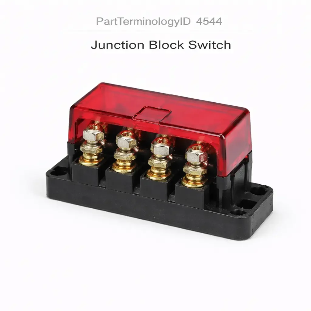
Junction Block Switch (PartTerminologyID 4544): Circuit Position Coverage, Contact Current Rating, and Junction Block Interface Compatibility
Written by Arthur Simitian | PartsAdvisory
PartTerminologyID 4544, Junction Block Switch, is the switch integrated into or mounted adjacent to the vehicle's fuse and relay junction block that provides driver-operated or system-controlled switching of one or more power distribution circuits within the junction block assembly, used in applications including master battery disconnect switches that isolate the vehicle's electrical system for maintenance or anti-theft purposes, auxiliary load switching circuits that allow the driver to activate secondary electrical loads (off-road lighting bars, air compressors, winches, or auxiliary accessories) through a dedicated switching element in the junction block rather than through separate standalone relays, and in some commercial and specialty vehicle applications multi-circuit control switches that govern multiple power distribution zones simultaneously from a single switch position within the block housing. That definition covers the junction block switching function correctly and leaves unresolved every question that determines whether the replacement switch is rated for the total current of all circuits it controls simultaneously in the junction block position, whether the switch body geometry matches the junction block housing's switch mounting aperture and retention method, whether the switch contact configuration matches the junction block's circuit design for the specific switched position, whether the switch is a latching type that maintains its switched state after activation or a momentary type that returns to the normal state when released, whether the switch includes an integrated indicator lamp that confirms the switched circuit's active state, and whether the switch is compatible with the junction block's specific mounting architecture including the connector type and pin assignment at the block's switch position.
It does not specify the current rating, body geometry, contact configuration, latching or momentary actuation type, indicator lamp type, or connector specification. A listing under PartTerminologyID 4544 that states only application description without current rating and contact configuration cannot be evaluated by a technician replacing a failed junction block auxiliary load switch on a commercial vehicle where the original switch carried 40 amperes through a latching contact to the auxiliary lighting relay coil supply, and the replacement is a momentary-contact type rated for 15 amperes, immediately failing under the first auxiliary lighting activation from both the current overload at the contact and the inability to hold the circuit closed without sustained switch pressure.
For sellers, PartTerminologyID 4544 covers a specialized application segment dominated by commercial vehicles, off-road and overlanding vehicles, marine applications, and fleet vehicles where the junction block is a customized power distribution center rather than a standard OEM fuse box. The buyer population is technically specific, having identified the junction block switch as the failed component and requiring an accurate current rating and form factor match to restore the switched circuit function safely.
What the Junction Block Switch Does
Master Battery Disconnect Application and the Full System Current Requirement
In the master battery disconnect application, the junction block switch interrupts the vehicle's entire electrical system by opening the main battery positive or negative supply circuit at the junction block. This application requires the switch to carry the vehicle's maximum possible simultaneous electrical load, which on a commercial vehicle with multiple motors, lighting systems, and electronic loads can reach 200 to 400 amperes during peak demand.
A master disconnect switch rated below the vehicle's peak current demand will arc and weld its contacts on the first full-load activation, leaving the vehicle's electrical system permanently connected regardless of switch position. The current rating for a master battery disconnect switch must be stated as both the continuous current rating (the sustained load the switch can carry indefinitely) and the interrupt current rating (the maximum current the switch can safely break at the contact gap without welding).
The distinction between continuous current rating and interrupt current rating is critical for battery disconnect switches because the interruption event at the contact opening produces an arc whose energy is proportional to the current being switched and the inductance of the disconnected circuit. A switch with a 200-ampere continuous rating but only a 50-ampere interrupt rating will weld its contacts when opened under a 150-ampere load even though the sustained load was within the continuous rating.
Auxiliary Load Switching and the Relay Coil versus Direct Load Architecture
Auxiliary load switching in junction blocks is implemented in two circuit architectures. In the relay-switched architecture, the junction block switch carries only the relay coil control current (typically 0.2 to 0.5 amperes) and the relay carries the full auxiliary load current. This architecture allows a small-rated switch to control very high current loads through the relay's power contacts. The switch in this position needs only a modest contact current rating for the relay coil circuit.
In the direct-switched architecture, the junction block switch carries the full auxiliary load current directly through its own contacts without an intermediate relay. This architecture requires a switch rated for the complete auxiliary load current, which for high-output off-road lighting or winch applications can reach 80 to 100 amperes. A relay coil-rated switch installed in a direct-switched auxiliary load position will weld its contacts on the first auxiliary load activation under the full load current.
Confirming which architecture is present requires identifying whether the switch's output feeds a relay coil input or a direct load supply line.
Top Return Scenarios
Scenario 1: "15-ampere switch in 40-ampere direct auxiliary load circuit, contacts weld on first activation"
The replacement switch is rated for 15 amperes. The junction block circuit routes 40 amperes directly through the switch to the auxiliary lighting load. On the first activation, the contacts close under 40 amperes and weld in the closed position. The auxiliary load cannot be deactivated and the junction block housing requires disassembly to interrupt the fused supply.
Prevention language: "Contact current rating: [X] amperes continuous, [X] amperes interrupt. Circuit architecture: [relay coil control circuit, [X] ampere coil current / direct load circuit, [X] ampere maximum load]. Verify both the continuous and interrupt current ratings against the maximum load current and the inductance of the switched circuit. Direct auxiliary load switches must be rated for the full load current plus the arc interrupt energy at contact opening."
Scenario 2: "Momentary switch in latching circuit position, auxiliary load deactivates when switch is released"
The replacement switch is a momentary contact type. The junction block circuit requires a latching switch that holds the auxiliary load active after a single press and releases it on a second press. After installation, the auxiliary lighting activates when the switch is pressed and held, and deactivates immediately when the switch is released rather than latching in the active state.
Prevention language: "Actuation type: [latching, maintains active state after single press / momentary, active only while switch is held]. Verify the actuation type against the junction block circuit design. A momentary switch in a latching circuit position will only maintain the switched circuit while the switch is physically held in the active position."
Scenario 3: "Switch body geometry does not match junction block housing aperture, switch cannot be retained securely"
The replacement switch body is 2mm narrower than the junction block housing aperture. The switch cannot be secured by the housing's retaining clip mechanism, which requires the switch body to press against the clip tabs at the correct contact geometry. The switch sits loosely in the aperture and vibrates under vehicle operation, producing intermittent contact at the switch terminals.
Prevention language: "Switch body dimensions: [width x height x depth in mm]. Verify the switch body geometry against the junction block housing's switch aperture. A switch body undersized for the aperture will not engage the housing's retaining mechanism, leaving the switch loose in the aperture and producing vibration-induced contact intermittency."
Core Listing Attributes for PartTerminologyID 4544
PartTerminologyID: 4544
Component: Junction Block Switch
Contact current rating: continuous in amperes and interrupt in amperes (mandatory, in title)
Circuit architecture: relay coil control or direct load circuit (mandatory)
Actuation type: latching or momentary (mandatory, in title)
Contact configuration: normally open or normally closed (mandatory)
Switch body dimensions: width, height, and depth in mm (mandatory)
Connector type and pin count at junction block interface (mandatory)
Indicator lamp: included with type and supply voltage, or not included (mandatory)
Application type: master battery disconnect, auxiliary load switching, or multi-circuit control (mandatory)
FAQ (Buyer Language)
How do I confirm whether my junction block switch controls a relay coil or a direct load?
Measure the current at the switch output terminal with the switch activated using a clamp-style ammeter. A reading of 0.1 to 0.5 amperes confirms a relay coil circuit. A reading of 10 amperes or more confirms a direct load circuit. Do not use a series ammeter in an unknown circuit without first confirming the expected current range to prevent damaging the meter.
What is the difference between continuous current rating and interrupt current rating?
The continuous current rating is the maximum current the switch contacts can carry indefinitely without overheating. The interrupt current rating is the maximum current the switch can safely break when opening the contacts without producing an arc that welds the contacts together. Both ratings must meet or exceed the actual circuit current. A high continuous rating with a low interrupt rating is inadequate for circuits where the switch must open under load.
Related PartTerminologyIDs
Fuse (if cataloged): the overcurrent protection device in the same junction block; the junction block switch controls circuit activation while the fuse protects against overcurrent; both are in the junction block but for different circuit protection purposes
Engine Shutdown Switch (PartTerminologyID 4392): covers engine-specific shutdown switches including battery isolation switches on racing applications; the junction block switch covers the broader range of switching applications at the junction block level
Status in New Databases
PIES/PCdb: PartTerminologyID 4544, Junction Block Switch
PIES 8.0 / PCdb 2.0: No change in PartTerminologyID or terminology label
Final Take for PartTerminologyID 4544
Junction Block Switch (PartTerminologyID 4544) is the power distribution PartTerminologyID where both the continuous current rating and the interrupt current rating must be confirmed separately, because a switch that carries the rated continuous load but cannot interrupt it at contact opening will weld its contacts on the first load break and eliminate the switching function permanently. State the continuous and interrupt current ratings in the title. State the actuation type in the title. State the circuit architecture. State the switch body dimensions. For PartTerminologyID 4544, interrupt current rating, actuation type, and circuit architecture are the three attributes that prevent the three most consequential return scenarios in the junction block switch buyer population.