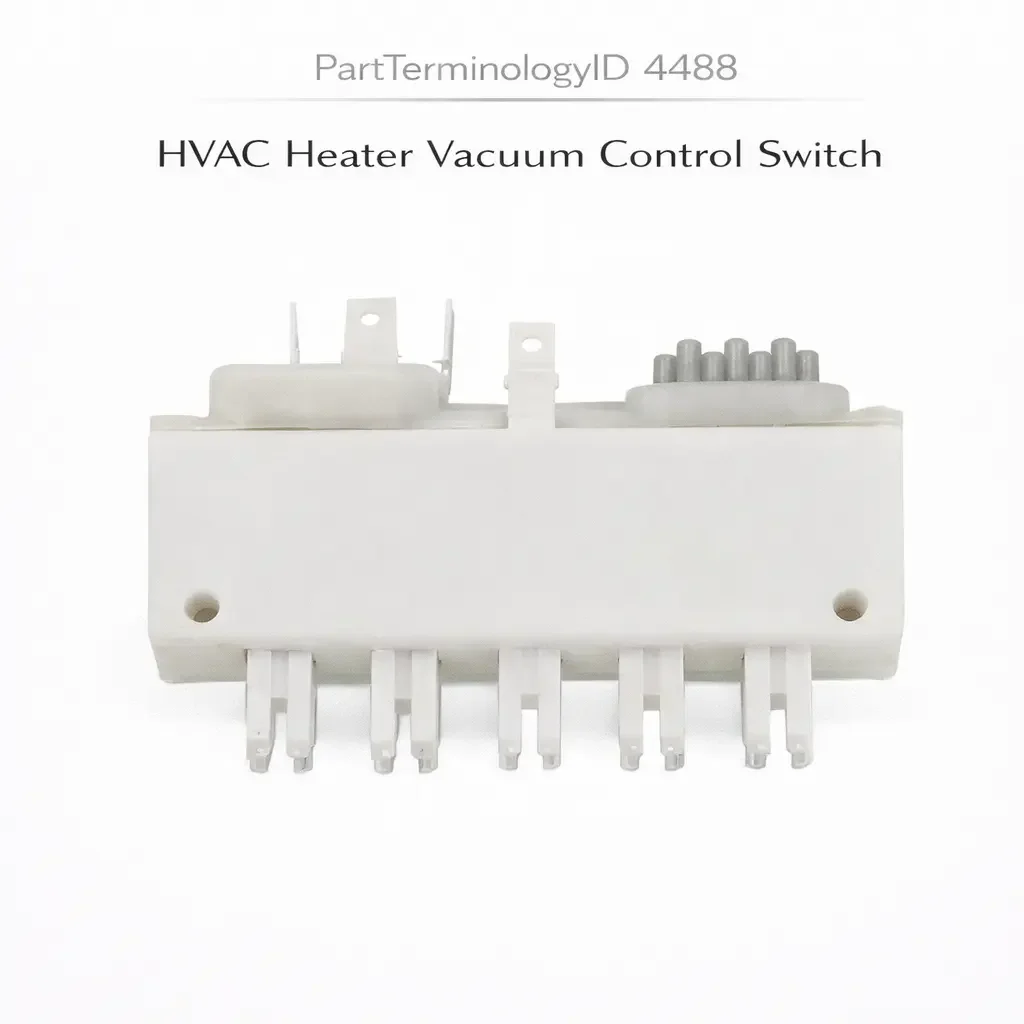
HVAC Heater Vacuum Control Switch (PartTerminologyID 4488): Vacuum Port Configuration, Mode Door Actuator Compatibility, and Rotary Position Calibration
Written by Arthur Simitian | PartsAdvisory
PartTerminologyID 4488, HVAC Heater Vacuum Control Switch, is the driver-operated rotary or sliding vacuum switching valve integrated into the heater control assembly that routes manifold vacuum or stored vacuum from a vacuum reservoir to the vacuum-operated mode door actuators, recirculation door actuators, and blend door actuators in the HVAC duct system, selecting the appropriate vacuum circuit for each heater mode position (floor, defrost, bi-level, vent, and combinations) by connecting specific vacuum outlets to the corresponding actuator vacuum ports while simultaneously blocking or venting the actuator ports for the inactive modes. That definition covers the vacuum routing and mode door actuation function correctly and leaves unresolved every question that determines whether the replacement switch's vacuum port layout matches the original's port-to-mode assignment for each rotary position, whether the switch body diameter and rotary detent spacing match the heater control panel's mounting aperture and control knob geometry, whether the switch includes the correct number of vacuum ports for all active mode door and actuator circuits in the specific vehicle's HVAC duct architecture, whether the switch's vacuum routing at each detent position matches the mode door actuator positions required for that mode, whether the switch is compatible with the vacuum reservoir volume and the manifold vacuum source that supplies the system, and whether the switch body's internal sealing is adequate to maintain vacuum at the actuated ports without leaking to the blocked or vented ports across the full rotary travel range.
It does not specify the port layout, port count, mode assignment per rotary position, body diameter, detent spacing, vacuum reservoir compatibility, or internal seal integrity. A listing under PartTerminologyID 4488 that states only year, make, and model without port count and port-to-mode assignment cannot be evaluated by a technician replacing a failed HVAC heater vacuum control switch on a vehicle where the original switch had seven vacuum ports with a specific floor-defrost-bi-level-vent port assignment sequence, and the replacement has seven ports with a different internal routing that produces the defrost mode door actuator position when the control knob is set to the floor position, directing all airflow through the defroster vents when the occupant selects floor heat on a cold morning.
For sellers, PartTerminologyID 4488 is the HVAC control PartTerminologyID where the vacuum port-to-mode assignment is the most consequential attribute and the most difficult to verify from a catalog listing because the vacuum routing internal to the switch body is not visible from the outside and can only be confirmed by measuring the vacuum continuity at each port for each rotary position. A replacement that physically matches the original in body diameter, port count, and connector appearance but has a different internal routing will produce incorrect mode door positions at some or all switch positions, and the specific failure pattern (floor mode producing defrost, vent producing bi-level) is not immediately identified as a switch routing mismatch without a systematic mode-by-mode vacuum continuity test.
What the HVAC Heater Vacuum Control Switch Does
Vacuum-Operated HVAC Mode Architecture and the Routing Switch Function
Before electronic actuator-controlled HVAC systems became standard from the mid-1990s onward, most domestic vehicles used engine manifold vacuum to operate the mode door actuators, recirculation door actuators, and in some cases the blend door actuator in the heater and air conditioning duct system. The vacuum-operated actuators are compact, reliable, and require no electrical power for their actuation function, using the engine's inherent manifold vacuum as a free energy source for HVAC door positioning.
The HVAC heater vacuum control switch is the routing valve that connects the vacuum supply to the appropriate actuator ports for each selected mode. For a typical five-mode system (off, vent, bi-level, floor, defrost), the switch must route vacuum to a different combination of actuator ports at each of the five detent positions. At the floor heat position, vacuum may be routed to the mode door actuator controlling the floor duct and the blend door actuator's heat position. At the defrost position, vacuum is routed to the defrost duct mode door actuator and the floor-to-defrost blend actuator. At the bi-level position, vacuum is routed simultaneously to both the floor and panel vent actuators.
The internal routing of the vacuum switch body is achieved through a set of rubber seals, o-rings, or molded passages within the rotary switch body that connect different combinations of ports as the knob rotates through each detent position. The exact routing sequence is designed to match the specific HVAC duct architecture of the vehicle, and it is not universal across makes, models, or even trim levels within the same model year.
Port Count, Port Position, and the Mode Assignment Sequence
The vacuum port count on the HVAC heater vacuum control switch equals the number of independent vacuum actuator circuits in the HVAC system plus the vacuum supply port. A simple four-mode system (vent, floor, bi-level, defrost) with three independent actuators requires four ports: one supply and three actuator ports. A more complex six-mode system with five actuators requires six ports. Some switches include an additional port for a vacuum reservoir check valve or for a recirculation door actuator independent of the mode selection.
The port positions on the switch body must align with the vacuum hose routing in the heater control panel and the HVAC duct assembly. The hose from each mode door actuator connects to a specific port on the switch body, and the switch's internal routing ensures the correct actuator is connected to vacuum at each mode position. If the replacement switch has the ports in the same physical positions but with a different internal routing, the mode door actuators connected to those ports will be driven to incorrect positions.
Confirming the port-to-mode assignment requires a vacuum pump and a pressure gauge. With the switch installed and the vacuum supply connected, each mode position should be tested to confirm that vacuum is present at the actuator port corresponding to that mode and absent at all other actuator ports. A switch with correct port count but incorrect internal routing will show vacuum at a different port than expected at one or more mode positions.
Rotary Detent Geometry and the Control Knob Interface
The rotary switch body must fit the heater control panel's mounting aperture and the control knob must engage the switch shaft at the correct spline or flat key interface. The switch body diameter is specific to the heater panel's mounting boss. A switch body too large will not fit the mounting aperture. A switch body too small will be loose in the aperture and may rotate within the panel rather than rotating with the control knob.
The detent spacing determines the angular interval between mode positions. A five-mode switch with equal detent spacing has 45-degree intervals between adjacent positions (assuming 180-degree total travel from first to last mode). A switch with different detent spacing than the original will produce mode transitions at different knob rotation angles than the occupant expects, potentially aligning one mode position's knob marking with an adjacent mode's vacuum routing state.
The control knob interface (spline count, flat key configuration, or D-shaft) must allow the original control knob to transfer to the replacement shaft. A shaft with a different spline count or different flat key configuration prevents knob transfer and requires sourcing a replacement knob that may not be readily available for older vehicles.
Vacuum Seal Integrity and the Leak Consequence
The internal seals in the vacuum switch body must maintain vacuum integrity at each port's connection zone while the switch is in any rotary position. A seal that allows vacuum to leak between adjacent port zones within the switch body will deliver vacuum to the actuator port for the selected mode and simultaneously allow that vacuum to bleed into the adjacent unselected port, partially actuating the adjacent mode door actuator while the selected mode is active.
The consequence of an internal vacuum leak is a mode that operates correctly for the first few seconds (while the vacuum reaches the actuated actuator) followed by a gradual drift of the unintended adjacent actuator as vacuum bleeds into its circuit through the leaking seal. The occupant experiences the selected mode operating initially but then observing the airflow pattern gradually shifting toward a partial blend of the selected mode and an adjacent mode, as if both mode doors are partially open simultaneously. This symptom is specific to internal seal leakage in the vacuum switch and is distinguishable from a failed vacuum actuator (which produces an immediate and fixed incorrect mode position) or a cracked vacuum hose (which produces a slow vacuum loss across the entire system).
Top Return Scenarios
Scenario 1: "Replacement has different internal routing, floor mode produces defrost duct airflow"
The buyer installs the replacement vacuum control switch. The switch body, port count, and knob fit correctly. Rotating the knob to the floor heat position directs airflow primarily through the defrost vents rather than the floor vents. The replacement's internal routing connects the defrost mode door actuator port to vacuum at the rotary position corresponding to floor mode. The floor mode door actuator receives no vacuum and its spring returns the door to the vent or defrost default position.
Prevention language: "Internal vacuum routing: mode-to-port assignment at each rotary position. Verify the vacuum continuity at each port for each mode position before installation. A replacement with identical port count but different internal routing produces incorrect mode door positions at some or all mode selections. Confirm by applying vacuum to the supply port and testing each actuator port at each detent position."
Scenario 2: "Seven-port replacement in five-port application, two extra ports provide vacuum to actuators that should be spring-returned"
The replacement switch has seven ports. The vehicle's HVAC system has five actuator circuits. The two extra ports in the replacement connect to actuators that should receive no vacuum in the vehicle's system. When vacuum is supplied to the replacement switch, the two extra ports route vacuum to the actuators connected there from the existing hose routing in the panel, actuating mode doors that the original switch left spring-returned in specific modes.
Prevention language: "Vacuum port count: [X] ports. Verify the port count against the original switch and the vehicle's actuator circuit count. A replacement with more ports than the original will provide vacuum to actuators that the original switch left vented or spring-returned, producing partial or incorrect mode door positions in specific modes."
Scenario 3: "Internal seal degradation, selected mode partially bleeds into adjacent mode, airflow gradually shifts"
The buyer installs the replacement switch. On first use, each mode produces correct airflow direction. After three weeks, the bi-level mode begins directing progressively more airflow to the floor vents and progressively less to the panel vents as the selected position is held. The internal seal between the bi-level and floor mode port zones has softened from the vacuum pressure differential and allows vacuum to bleed into the floor mode port while the bi-level position is selected.
Prevention language: "Internal seal material: [specify material and temperature rating]. Verify the internal seal material is appropriate for the vacuum supply temperature at the switch mounting position. A seal that softens under sustained vacuum pressure differential will allow bleed between adjacent port zones, producing gradual mode drift while the selected mode is held."
Scenario 4: "Shaft spline count does not match original knob, knob cannot be transferred, switch inoperable without knob"
The buyer replaces the vacuum control switch body. The original control knob is retained for transfer. The replacement shaft has a six-spline profile. The original knob has a four-spline bore. The knob cannot be seated on the replacement shaft. The original switch body's shaft is destroyed by the failure that prompted the replacement, preventing reinstallation of the old shaft. No replacement knob is available from the seller.
Prevention language: "Shaft interface: [X]-spline, [X]-flat key, or D-shaft. Knob: [included / not included, transfer original]. Verify the shaft interface against the original control knob before ordering. A spline count or key configuration mismatch prevents knob transfer and leaves the switch body inoperable without a separately sourced knob."
Core Listing Attributes for PartTerminologyID 4488
PartTerminologyID: 4488
Component: HVAC Heater Vacuum Control Switch
Vacuum port count (mandatory, in title)
Mode-to-port assignment at each rotary position (mandatory)
Rotary position count and detent spacing (mandatory)
Switch body outer diameter in mm (mandatory)
Shaft interface type and spline or key count (mandatory)
Knob: included or not included with transfer note (mandatory)
Vacuum supply port identification (mandatory)
Internal seal material and temperature rating (mandatory)
Year/make/model/engine/HVAC duct configuration
Catalog Checklist for ACES/PIES Teams
PartTerminologyID = 4488
Require vacuum port count in title (mandatory)
Require mode-to-port assignment documentation at each rotary position (mandatory)
Require switch body diameter (mandatory)
Require shaft interface type and count (mandatory)
Require knob inclusion status (mandatory)
Require internal seal material (mandatory)
Prevent port count omission: a replacement with more or fewer ports than the original routes vacuum to incorrect actuators or leaves active actuators without control; port count must match the vehicle's actuator circuit count exactly
Prevent mode assignment omission: a replacement with identical port count but different internal routing produces incorrect mode door positions; mode-to-port assignment must be verified by vacuum continuity testing at each position
Prevent shaft interface omission: a spline count mismatch prevents knob transfer; shaft interface must be confirmed against the original knob before ordering
Prevent seal material omission: an underrated seal material softens under sustained vacuum and produces gradual mode drift; seal material and rating must be confirmed for the installation temperature environment
Differentiate from HVAC Heater Control Switch (PartTerminologyID 4484): the heater control switch is the complete assembly including electrical mode and fan speed control; the heater vacuum control switch is specifically the vacuum routing valve portion of the control assembly; on vehicles where both electrical and vacuum control are in the same assembly, PartTerminologyID 4484 covers the complete assembly
Differentiate from Vacuum Check Valve (if cataloged): the check valve maintains stored vacuum in the reservoir when engine vacuum drops; the vacuum control switch routes stored or live vacuum to mode actuators; both are in the HVAC vacuum circuit but at different positions for different functions
FAQ (Buyer Language)
How do I confirm the vacuum port-to-mode assignment of my original switch?
With the original switch installed and the engine running, connect a vacuum gauge sequentially to each actuator port while rotating the mode knob through all positions. Record which port shows vacuum at each knob position. This map confirms the original switch's mode-to-port assignment. Compare this map to the replacement switch's stated port assignment before installation.
My heater produces the wrong airflow direction after replacing the vacuum control switch. What is the most likely cause?
An incorrect airflow direction after vacuum switch replacement is almost always caused by a different internal routing in the replacement switch mapping the vacuum supply to a different actuator port at the selected mode position. Confirm the mode-to-port assignment of the installed replacement by testing vacuum continuity at each port for the selected mode and comparing to the original's documented assignment.
Can I repair the vacuum seals inside the switch instead of replacing the entire switch?
On some switches, the internal seals are accessible after removing the switch from the panel and disassembling the rotary body. Seal repair kits are available for common switch types from suppliers of heater control restoration components. Seal repair is appropriate when the switch body, shaft, and port geometry are all correct and only the internal seals have degraded. If the internal routing is also incorrect, a seal repair on a wrong-routing switch still produces incorrect mode positions.
Related PartTerminologyIDs
HVAC Heater Control Switch (PartTerminologyID 4484): the complete heater control assembly; on vehicles where the vacuum routing switch is integrated into the heater control assembly body, PartTerminologyID 4484 covers the complete assembly including both the electrical control and the vacuum routing functions
HVAC Vacuum Actuator (if cataloged): the vacuum-operated actuator the switch routes vacuum to; a switch that routes vacuum correctly but the mode door does not move confirms a failed actuator diaphragm rather than a switch fault; test actuator function by applying direct vacuum to the actuator port before replacing the switch on an incorrect mode position complaint
Status in New Databases
PIES/PCdb: PartTerminologyID 4488, HVAC Heater Vacuum Control Switch
PIES 8.0 / PCdb 2.0: No change in PartTerminologyID or terminology label
Final Take for PartTerminologyID 4488
HVAC Heater Vacuum Control Switch (PartTerminologyID 4488) is the vacuum routing PartTerminologyID where the internal port-to-mode assignment is the primary specification and the most difficult to verify from a catalog listing alone, because a switch with the correct port count, correct body diameter, and correct shaft interface can still route vacuum to the wrong actuators at specific mode positions if its internal routing differs from the original. The only reliable verification is a vacuum continuity test at each port for each mode position, which must be confirmed against the original switch's documented assignment before installation.
State the vacuum port count in the title. State the mode-to-port assignment at each rotary position. State the switch body diameter. State the shaft interface type and count. State the knob inclusion status. State the internal seal material. For PartTerminologyID 4488, mode-to-port assignment, port count, and shaft interface are the three attributes that prevent the three most consequential and least visually obvious return scenarios in the HVAC heater vacuum control switch buyer population.