HVAC Heater Control Switch (PartTerminologyID 4484): Control Architecture, Temperature Blend Signal Compatibility, and Integrated Function Coverage
Written by Arthur Simitian | PartsAdvisory
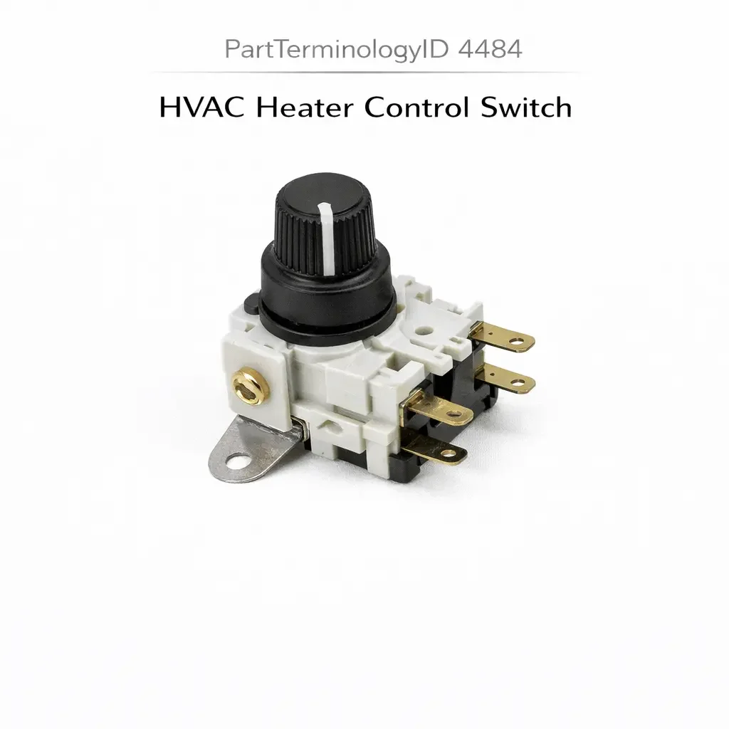
PartTerminologyID 4484, HVAC Heater Control Switch, is the driver-operated control assembly that governs the vehicle's heater system operation by providing inputs for temperature blend door position, mode selection (floor, defrost, bi-level, and vent), fan speed selection, and in some configurations the recirculation door position, communicating these commands to the blend door actuator, the mode door actuators, the blower motor resistor circuit or blower motor control module, and the recirculation door actuator through direct control signals, analog resistance outputs, or serial bus digital commands depending on the vehicle's climate control architecture, and distinguished from PartTerminologyID 4396 (HVAC System Switch) by its specific focus on heating and defrost function management rather than the broader integrated climate control assembly that governs A/C compressor engagement and automatic climate control in addition to heating. That definition covers the heater control function correctly and leaves unresolved every question that determines whether the replacement switch assembly's signal architecture matches the original climate system's communication method, whether the connector pin count and terminal assignment match the harness at the instrument panel mounting position, whether the replacement covers the same temperature blend range and the same set of mode positions as the original, whether the switch is compatible with the blend door actuator's input signal type on vehicles where the actuator expects a specific resistance range or voltage range rather than a simple contact position, whether the replacement's fan speed step count and signal type match the blower motor resistor pack or blower control module downstream, whether the switch illumination elements match the instrument panel lighting supply and dimmer architecture, and whether the replacement requires programming after installation on vehicles with serial bus climate control.
It does not specify the signal architecture, connector pin count, temperature blend range, mode position coverage, fan speed compatibility, illumination type, or programming requirement. A listing under PartTerminologyID 4484 that states only year, make, and model without signal architecture and temperature blend output range cannot be evaluated by a technician replacing a failed heater control switch on a vehicle where the original switch produced a 0 to 5 volt analog output to a blend door actuator with a 0 to 5 volt input range, and the replacement produces a 0 to 3.5 volt output, limiting the blend door to 70 percent of its full travel and preventing the heater from delivering maximum heat output at any switch position, producing a cabin that never reaches the original maximum heat output on the coldest winter mornings.
For sellers, PartTerminologyID 4484 is closely related to PartTerminologyID 4396 (HVAC System Switch) and the two PartTerminologyIDs address overlapping applications. PartTerminologyID 4396 covers the complete integrated HVAC control assembly on vehicles where a single panel governs heating, A/C, and all associated functions together. PartTerminologyID 4484 covers the heater-specific control assembly on vehicles where the heating system has a dedicated control separate from the A/C control, or on vehicles where the heating control is the only climate control present (no A/C). The most common applications in PartTerminologyID 4484 are vehicles without factory A/C where the heater control is a simpler two or three-function assembly, commercial vehicles with dedicated heater controls independent of the main climate panel, and rear HVAC heater controls in vans and SUVs that govern only the rear heating zone independently.
What the HVAC Heater Control Switch Does
Heater-Only versus Integrated HVAC Architecture and the Function Set Distinction
The HVAC heater control switch in its simplest form governs three functions: temperature blend (the proportion of heated to unheated air delivered through the vents), mode selection (floor, defrost, bi-level, or vent), and fan speed. On vehicles without A/C, these three functions represent the complete climate control capability. The switch assembly may be a rotary knob cluster with three independent knobs (one for each function), a sliding lever cluster, or a single integrated rotary assembly with multiple control tracks.
On commercial vehicles, vans, and SUVs with rear HVAC zones, the rear heater control switch governs only the rear zone's fan speed, temperature blend, and sometimes mode selection, independently of the front climate control panel. The rear heater switch is typically simpler than the front assembly, covering fewer mode positions and a single fan speed range calibrated for the rear zone's lower airflow requirements.
The function set covered by the replacement must match the original exactly. A rear zone heater switch that covers three fan speeds where the original covered five will leave the rear occupants without the two highest fan speed positions, producing inadequate heating at maximum demand on the coldest days. A switch that covers four mode positions where the original covered six leaves the rear defrost and bi-level modes permanently inaccessible.
Temperature Blend Signal and the Actuator Compatibility Requirement
The temperature blend control governs the blend door actuator, which mixes heated and unheated air to produce the commanded cabin temperature. The blend door actuator receives a position command from the heater control switch and drives the blend door to the corresponding position. The signal type and range of this command must match the actuator's input specification exactly.
On direct cable systems (older vehicles and commercial trucks), the temperature blend is governed by a Bowden cable directly connecting the switch's temperature lever to the blend door without any electrical signal. The cable geometry and cable attachment method must match the original cable routing. A cable attachment point in the wrong position on the replacement switch body produces a blend door that does not reach the full heat or full cool positions at the corresponding switch lever positions.
On electrical signal systems, the switch produces a variable resistance or variable voltage output that the blend door actuator motor or control module uses to determine the commanded blend door position. A switch producing a 200 to 1000 ohm output range in a system calibrated for a 500 to 4500 ohm range will command the blend door only through a fraction of its available travel, producing a temperature regulation range that does not extend to the full heat or full cool extremes at the switch's end positions.
Mode Position Coverage and the Airflow Pattern Dependency
The mode selection function directs conditioned air through the appropriate duct outlets: floor vents for heating, defrost vents for windshield clearing, bi-level for floor and face simultaneous delivery, or panel vents for driver and passenger face-level airflow. Each mode position activates specific mode door actuators or vacuum-operated mode doors to route airflow through the correct ducts.
A replacement switch with fewer mode positions than the original leaves some duct routing options permanently unavailable. On vehicles where the defrost mode is a critical safety function for windshield visibility, a switch missing the defrost position removes the driver's ability to clear the windshield through the climate system. The defrost mode position must always be present in the replacement and must produce the correct signal to the mode door actuators for the defrost duct configuration.
The mode positions vary in their signal encoding. Direct contact array systems use discrete contact closures for each mode position, with the switch body routing the current to the specific mode door actuator motor connection for the selected mode. Resistance-encoded systems present a specific resistance value to the HVAC control module's input for each mode position. Serial bus systems transmit a digital mode command on the vehicle network.
Fan Speed Step Count and the Resistor Pack or Module Compatibility
The fan speed control section of the heater control switch must match the downstream blower circuit architecture and step count, following the same requirements described in PartTerminologyID 4252 (HVAC Blower Control Switch). A switch covering three fan speeds in a four-speed resistor pack circuit leaves the fourth speed permanently inaccessible. A switch producing variable resistance output in a direct contact array resistor pack circuit presents a non-standard signal to the resistor pack tap selection and produces unpredictable fan speed behavior.
On rear HVAC heater assemblies, the fan speed step count is typically fewer than the front assembly because the rear zone's lower airflow requirements are adequately served by a two or three-speed range. Confirming the rear zone's specific fan speed count is as important as confirming the front assembly's count.
Illumination Compatibility and the Instrument Panel Dimmer Integration
The heater control switch illumination elements must be compatible with the instrument panel lighting circuit supply voltage and dimmer architecture, following the same conventions described in PartTerminologyID 4340 (Dimmer Switch) and PartTerminologyID 4396 (HVAC System Switch). An incandescent replacement in a PWM-dimmer LED circuit draws excess current and produces dimmer module thermal protection reduction of all panel illumination. An LED replacement with a fixed forward voltage in a resistive dimmer circuit produces non-proportional brightness response to the dimmer control.
Rear HVAC Zone Heater Control Specifics
Rear zone fan speed range and temperature blend calibration
The rear HVAC heater switch in a van or SUV governs the rear zone's climate independently of the front zone. The rear blower motor is typically a smaller unit than the front, drawing less current and requiring a separate blower motor resistor pack or blower control module calibrated for the rear motor's lower current draw. The fan speed step count for the rear zone is often fewer (two or three steps) than the front zone (four to six steps).
The temperature blend for the rear zone may be governed by a separate blend door actuator in the rear HVAC module. The rear zone temperature blend control on the switch must produce the signal type and range that the rear blend door actuator expects. On systems where the front and rear blend doors share a common actuator type, the signal ranges are typically identical. On systems where the rear zone uses a different actuator model than the front, the signal range may differ.
A replacement rear heater switch with the front zone's fan speed step count and temperature blend output range will not match the rear blower circuit's resistor pack or the rear blend door actuator's input calibration. The rear zone may produce incorrect fan speeds and limited temperature blend range after the replacement.
Mode position coverage for rear zone defrost
Many rear HVAC heater assemblies in SUVs and vans include a rear window defrost output integrated into the rear climate control panel, allowing the rear occupant or the driver (depending on the vehicle's control routing) to activate the rear window defrost grid from the rear climate panel rather than requiring a separate front panel switch press. The rear window defrost output in the rear heater control switch must connect to the same circuit as the front panel's defrost switch or the BCM's rear defrost input.
A replacement rear heater switch without the rear window defrost position removes the rear occupant's ability to activate the rear defrost from the rear climate panel. On vehicles where the rear panel is the primary rear defrost control location (particularly in rear-passenger-operated climate zones in luxury SUVs), this function loss is immediately noticed by rear occupants.
Why This Part Generates Returns
Buyers return HVAC heater control switches because the temperature blend output range is 0 to 3.5 volts and the blend door actuator requires 0 to 5 volts, limiting the blend door to 70 percent travel and preventing maximum heat output; the mode position coverage includes four positions and the original included six, leaving the rear defrost and bi-level modes inaccessible; the fan speed step count is three and the downstream resistor pack has five taps, leaving the two highest fan speeds permanently unavailable; the connector is a twelve-pin type and the harness at the rear HVAC module has a sixteen-pin connector covering the rear defrost output and rear zone mode positions absent in the twelve-pin replacement; the switch requires serial bus initialization after installation and the listing describes it as plug-and-play, leaving the heater system unresponsive after installation; the temperature blend cable attachment point in the replacement is 8mm lower on the switch body than in the original, preventing the cable from reaching the full heat position and limiting maximum heat output; and the illumination elements draw 2.1 amperes total in a rear climate panel circuit designed for LED illumination drawing 0.25 amperes, causing the instrument panel dimmer module to reduce all panel illumination in thermal protection.
Top Return Scenarios
Scenario 1: "Temperature blend output 0 to 3.5 volts, actuator requires 0 to 5 volts, maximum heat output limited to 70 percent"
The buyer installs the replacement front heater control switch. All mode positions respond correctly and the fan speed changes work. On a minus 10 degree Celsius morning, the temperature blend is set to maximum heat but the cabin does not reach the warmth the original delivered. The replacement's temperature blend output reaches 3.5 volts at the full heat position. The blend door actuator is calibrated to move to the full heat position at 5 volts. The blend door reaches only 70 percent of its full heat travel at the replacement switch's maximum output.
Prevention language: "Temperature blend output range: [minimum X volts to maximum X volts] or [minimum X ohms to maximum X ohms]. Verify the output range against the blend door actuator's commanded input range. A replacement with a lower maximum output limits the blend door to a fraction of its full travel, preventing maximum heat or cooling output at the switch's end positions."
Scenario 2: "Four mode positions in original six-position application, rear defrost and bi-level absent"
The buyer replaces the heater control switch. Floor, vent, and front defrost modes respond correctly. The rear window defrost mode position is absent. The bi-level mode position is absent. The rear window cannot be defrosted from the climate panel and the bi-level airflow distribution cannot be selected.
Prevention language: "Mode position coverage: [list all positions: floor, vent, bi-level, front defrost, rear defrost, and others as applicable]. Verify the mode position count against the original switch. A replacement with fewer mode positions than the original leaves the omitted duct routing options permanently inaccessible from the climate panel."
Scenario 3: "Three-speed fan in five-tap resistor pack, two highest fan speeds permanently unavailable"
The replacement switch covers three fan speed positions. The blower motor resistor pack has five taps. After installation, positions one through three route to the first three resistor taps correctly. The fourth and fifth resistor taps receive no switching signal from the three-speed switch, leaving those two speed levels inaccessible. On the coldest days when maximum airflow is needed, the blower runs at the third-highest speed rather than the maximum.
Prevention language: "Fan speed step count: [X] speeds. Downstream resistor pack tap count: [X] taps. Verify the fan speed step count against the resistor pack tap count. A switch with fewer steps than the resistor pack taps leaves the higher speed positions permanently inaccessible. Maximum heating airflow is unavailable at any switch position."
Scenario 4: "Serial bus switch requires initialization, listed as plug-and-play, heater system unresponsive after installation"
The buyer installs the replacement on a van with a serial bus rear climate control system. No mode change, temperature adjustment, or fan speed input produces any response after installation. The rear HVAC module requires the new switch's bus address to be registered before it accepts commands. The listing states no programming is required. The buyer cannot source scan tool access before a winter camping trip.
Prevention language: "Post-installation programming: [not required, self-initializing / required, rear HVAC module registration with [scan tool type]]. Failure to complete registration results in no heater response on any switch input. Confirm scan tool availability before ordering for a serial bus rear climate system."
Scenario 5: "Cable attachment point 8mm too low on replacement body, cable cannot reach full heat position"
The buyer replaces the temperature blend cable-operated heater switch. After installation and cable reconnection, the temperature blend operates from the cool position through approximately 80 percent of travel before the cable reaches its attachment point limit on the replacement switch body. The remaining 20 percent of blend door travel toward maximum heat cannot be commanded from the switch because the cable runs out of travel before the switch lever reaches its mechanical stop.
Prevention language: "Temperature blend cable attachment point position: [X mm from switch body reference]. Verify the cable attachment geometry matches the original switch before ordering. A cable attachment point in the wrong position on the replacement body prevents the cable from reaching the full heat or full cool extreme, limiting the commanded blend door travel range."
Scenario 6: "Twelve-pin replacement in sixteen-pin rear HVAC harness, rear defrost output and rear mode circuits unconnected"
The buyer replaces the rear HVAC heater switch in a three-row SUV. The replacement uses a twelve-pin connector. The harness at the rear climate panel position uses a sixteen-pin connector covering rear zone defrost output, rear zone mode selection, rear zone fan speed, temperature blend, and illumination. Four circuits are unconnected in the replacement. The rear window defrost cannot be activated from the rear panel and the rear zone cannot select any mode other than the default.
Prevention language: "Connector pin count: [X] pins covering [rear fan speed, temperature blend, mode selection, rear defrost output, illumination, ground, and supply as applicable]. Verify pin count against the rear HVAC harness connector. A replacement with fewer pins than the original leaves the circuits for rear defrost activation and rear mode selection permanently unconnected."
Core Listing Attributes for PartTerminologyID 4484
PartTerminologyID: 4484
Component: HVAC Heater Control Switch
Zone coverage: front zone, rear zone, or combined front and rear (mandatory, in title)
Signal architecture: direct contact array, analog resistance, analog voltage, or serial bus with protocol (mandatory, in title)
Temperature blend output type and range: voltage or resistance minimum and maximum (mandatory)
Mode position count with all positions listed (mandatory)
Fan speed step count and signal type (mandatory)
Connector pin count with function mapping for each pin (mandatory)
Cable attachment geometry for cable-operated types: attachment point position in mm (mandatory)
Illumination type: incandescent with current draw, or LED with PWM compatibility (mandatory)
Rear window defrost output: included or not included (mandatory)
Post-installation programming requirement: none or tool and procedure required (mandatory for serial bus types)
Year/make/model/submodel/trim/zone configuration
Note for trim levels where function coverage differs on the same platform
Note for production date range where signal architecture or position count changed
Note for rear zone applications requiring different resistor pack or module specification than front zone
Catalog Checklist for ACES/PIES Teams
PartTerminologyID = 4484
Require zone coverage in title: front, rear, or combined (mandatory)
Require signal architecture in title (mandatory)
Require temperature blend output type and range (mandatory)
Require mode position count with all positions listed (mandatory)
Require fan speed step count and signal type (mandatory)
Require connector pin count with function mapping (mandatory)
Require rear window defrost output status (mandatory)
Require programming disclosure for serial bus types (mandatory)
Prevent temperature blend range omission: a replacement with a lower maximum output limits blend door travel and prevents maximum heat or cooling output; output range must be stated and verified against the actuator's input specification
Prevent mode position count omission: a replacement missing the defrost mode removes windshield clearing capability from the climate panel; all mode positions must be listed and confirmed
Prevent fan speed step count omission: a switch with fewer steps than the resistor pack taps leaves the highest fan speeds permanently unavailable on the coldest days; step count must match the downstream circuit
Prevent rear defrost output omission: a rear zone switch without the defrost output removes rear window clearing capability from the rear panel position; output status must be stated
Prevent serial bus programming omission: a switch requiring initialization listed as plug-and-play leaves the heater system unresponsive after installation; programming requirement must be disclosed
Relationship to PartTerminologyID 4396 (HVAC System Switch): the HVAC system switch covers the complete integrated front climate control assembly including A/C compressor engagement and automatic climate control; the heater control switch covers heating-only systems, commercial vehicle heater controls, and rear zone heater assemblies; confirm which PartTerminologyID applies to the specific application before ordering
Relationship to PartTerminologyID 4252 (HVAC Blower Control Switch): the blower control switch is the standalone fan speed control where the fan is a separate switch from the heater control; when fan speed is integrated into the heater control assembly, PartTerminologyID 4484 covers both functions in the same assembly
Differentiate from HVAC System Switch (PartTerminologyID 4396): PartTerminologyID 4396 covers the complete front integrated HVAC assembly with A/C and automatic climate control; PartTerminologyID 4484 covers heating-focused controls without A/C integration or rear zone heater controls
FAQ (Buyer Language)
How do I identify whether my vehicle uses PartTerminologyID 4396 or 4484 for the climate control switch?
If the climate panel includes an A/C button or an auto mode button alongside the temperature and fan controls, the assembly is a complete HVAC system switch covered by PartTerminologyID 4396. If the climate panel has only temperature blend, mode selection, and fan speed (no A/C or auto mode input), the assembly is a heater control switch covered by PartTerminologyID 4484.
Why does my heater not reach full heat after replacing the control switch?
A heater that cannot reach maximum heat output after switch replacement typically indicates a temperature blend output range mismatch. The replacement switch's maximum output is below the blend door actuator's full heat input threshold. Confirm the replacement switch's temperature blend maximum output against the blend door actuator's full travel command voltage or resistance. If the outputs differ, a different replacement with the correct output range is required.
My defrost mode does not work after replacing the heater switch. The other modes work correctly. What happened?
A defrost mode that does not respond after switch replacement while other modes work confirms either a mode position count mismatch (the replacement does not include a defrost mode position) or a contact or signal mismatch at the defrost position specifically. Confirm whether the replacement switch includes a dedicated defrost position and whether the defrost signal pin is connected and producing the correct output at the defrost switch position.
Can I use a front HVAC heater switch to replace a failed rear zone heater switch?
No. The front and rear zone heater switches have different fan speed step counts, different temperature blend output calibrations for the respective zone's actuator, and often different mode position coverage. The rear zone switch may also include a rear window defrost output absent in the front switch. Front and rear zone switches are not interchangeable even when the switch body appearances are similar.
Does the rear HVAC heater switch need programming after installation?
On direct contact and analog signal rear climate systems, no programming is required. On serial bus rear climate systems (more common on premium vehicles with independent rear climate control), programming is often required. Confirm the rear zone's signal architecture from the vehicle's service manual before ordering.
Related PartTerminologyIDs
HVAC System Switch (PartTerminologyID 4396): the complete integrated front HVAC control assembly including A/C and automatic climate control; on vehicles where the front climate panel includes A/C compressor control and automatic mode, PartTerminologyID 4396 is the correct assembly rather than 4484
HVAC Blower Control Switch (PartTerminologyID 4252): the standalone fan speed switch on vehicles where fan control is separate from the heater control assembly; when fan speed is integrated into the heater control switch body, PartTerminologyID 4484 covers both
Blend Door Actuator (if cataloged): the motor driving the temperature blend door; a correctly functioning heater control switch with no temperature change response confirms a failed blend door actuator rather than a switch fault; confirm actuator function before replacing the switch on a no-temperature-change complaint
Rear Window Defrost Switch (PartTerminologyID 4336): the standalone rear defroster switch on vehicles where defrost is not integrated into the heater control panel; on vehicles where the rear defrost is activated from the rear HVAC heater control switch, PartTerminologyID 4484 covers that function within the assembly
Status in New Databases
PIES/PCdb: PartTerminologyID 4484, HVAC Heater Control Switch
PIES 8.0 / PCdb 2.0: No change in PartTerminologyID or terminology label
Final Take for PartTerminologyID 4484
HVAC Heater Control Switch (PartTerminologyID 4484) is the climate control PartTerminologyID where temperature blend output range, mode position count, and fan speed step count must each be confirmed independently, because a mismatch in any one produces a specific and persistent limitation in climate system capability: a blend door that cannot reach maximum heat, a mode selection that cannot access defrost, or a fan that cannot reach maximum airflow. None of these limitations produces an error code or an obvious failure symptom at installation, and all three manifest only when the driver attempts to use the affected function in the conditions where it is most needed.
State the zone coverage in the title. State the signal architecture in the title. State the temperature blend output range. State all mode positions. State the fan speed step count. State the connector pin count with function mapping. State the rear window defrost output status. State the programming requirement for serial bus types. For PartTerminologyID 4484, temperature blend output range, mode position count, and fan speed step count are the three attributes that prevent the three most consequential and least immediately obvious return scenarios in the HVAC heater control switch buyer population.