Heat Shield Switch (PartTerminologyID 4478): Temperature Threshold Calibration, Contact Configuration, and Protected Circuit Compatibility
Written by Arthur Simitian | PartsAdvisory
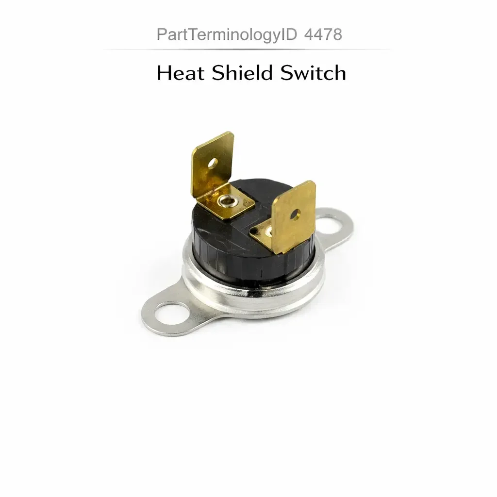
PartTerminologyID 4478, Heat Shield Switch, is the thermostatic switch mounted in proximity to a heat-generating component such as the exhaust manifold, catalytic converter, turbocharger housing, or engine block that monitors the surface temperature or ambient temperature at the protected position and opens or closes an electrical contact when the temperature exceeds a calibrated threshold, activating a cooling fan, a heat warning indicator, a fuel system heat protection circuit, or a vapor recovery system control circuit to protect adjacent temperature-sensitive components from thermal damage. That definition covers the temperature monitoring and circuit activation function correctly and leaves unresolved every question that determines whether the replacement switch's temperature activation threshold matches the original calibration for the specific protected component's temperature tolerance and the heat-generating component's operating temperature range, whether the switch is a normally open type that closes on temperature rise or a normally closed type that opens on temperature rise depending on the circuit design, whether the switch mounting method matches the original installation position (threaded port, clamp bracket, or adhesive-mounted probe), whether the switch body is rated for the surface temperature at the installation point which may exceed the ambient air temperature the switch sensing element monitors, and whether the switch connector type and current rating match the circuit it controls.
It does not specify the temperature threshold, contact configuration, mounting method, body temperature rating, connector type, or circuit current rating. A listing under PartTerminologyID 4478 that states only application description without threshold and contact configuration cannot be evaluated by a technician replacing a failed heat shield switch on a vehicle where the original switch closed its contact at 120 degrees Celsius to activate the underhood cooling fan when the catalytic converter area temperature exceeded the threshold, and the replacement is a normally closed type that opens at 120 degrees Celsius, deactivating the fan precisely when the catalytic converter temperature calls for maximum cooling rather than activating it.
For sellers, PartTerminologyID 4478 covers a relatively narrow application set dominated by underhood thermal management circuits on turbocharged and high-output engines, fuel system vapor recovery heat protection circuits on vehicles where the fuel system components are in proximity to the exhaust, and catalytic converter heat shielding circuits where an auxiliary fan or a cooling circuit is activated by detected over-temperature at the converter position. The buyer population is technically precise, having already confirmed the thermal management circuit requires a switch replacement rather than a sensor, and requires accurate threshold and contact configuration information to restore the original protection function.
What the Heat Shield Switch Does
Thermal Protection Circuit Function and the Threshold Calibration Requirement
The heat shield switch protects temperature-sensitive components in the vehicle's underhood environment by activating a cooling or warning circuit before the protected component reaches its thermal damage threshold. The switch threshold is set below the protected component's damage temperature but above the maximum temperature the component experiences during normal operation, so the switch activates only when thermal conditions exceed the normal range and intervention is required.
A switch with a threshold set too low activates the cooling fan or warning circuit during normal high-load operation where the temperature is elevated but within the designed operating range, producing a nuisance activation that the driver or ECU may interpret as a fault. A switch with a threshold set too high fails to activate until the temperature has already reached or exceeded the protected component's thermal tolerance, reducing or eliminating the protection margin.
The activation threshold is specific to the installation position and the protected component. A heat shield switch protecting a plastic fuel canister near the exhaust may be calibrated at 80 degrees Celsius because the canister's temperature limit is 90 degrees Celsius and the exhaust-adjacent ambient temperature rarely exceeds 70 degrees Celsius under normal conditions. A switch protecting a turbocharger bearing cooling circuit may be calibrated at 150 degrees Celsius because the bearing cavity temperature at normal boost operation reaches 140 degrees Celsius and the threshold must be above this to prevent continuous fan activation during normal operation.
Contact Configuration and the Protection Circuit Logic
The contact configuration determines whether the protection circuit activates or deactivates at the threshold. A normally open switch that closes at threshold is used in circuits where the protection function is activated by the temperature reaching the threshold: the cooling fan relay coil circuit is completed when the switch closes, activating the fan. A normally closed switch that opens at threshold is used in circuits where a sustained closure holds a protection lockout and the opening at threshold releases or activates the protected circuit.
The most consequential mismatch in this PartTerminologyID is the same reversal described across adjacent thermal switch PartTerminologyIDs: a normally closed switch in a normally open circuit deactivates the protection function precisely at the threshold temperature rather than activating it, providing no thermal protection during the highest-temperature events the switch was designed to detect.
Mounting Method and Body Temperature Rating
The heat shield switch is installed at or near the heat-generating source using one of three mounting configurations. The threaded port type threads into a port on the exhaust manifold, catalytic converter housing, or turbocharger body, placing the sensing element in direct contact with the component surface. The clamp bracket type positions the switch body adjacent to the heat source using a metal bracket that clamps to an exhaust pipe or heat shield panel. The probe type uses a temperature probe on an extending stalk that is positioned at a specific distance from the heat source within the underhood environment.
The switch body itself must be rated for the surface temperature at the installation position, which may be significantly higher than the ambient air temperature the sensing element monitors. A threaded switch installed on a catalytic converter housing must withstand the converter's full operating temperature at the housing surface (up to 400 to 600 degrees Celsius at the converter surface) even though the switch's activation threshold may be calibrated to the ambient temperature 50mm away from the surface at a much lower value. The switch body material and the thread material must be rated for the surface temperature, not merely the activation threshold.
Top Return Scenarios
Scenario 1: "Normally closed switch in normally open cooling fan circuit, fan deactivates at threshold"
The replacement switch is normally closed. The cooling fan relay circuit requires normally open. At normal underhood temperatures, the normally closed contact completes the relay circuit and the cooling fan runs continuously. When the temperature reaches the threshold, the switch opens, de-energizing the relay and stopping the fan precisely when the catalytic converter area is hottest and cooling is most needed.
Prevention language: "Contact configuration: [normally open, closes at threshold to activate protection circuit / normally closed, opens at threshold]. Verify the configuration against the protection circuit design. A normally closed switch in a normally open circuit activates the protection fan during normal operation and deactivates it at the threshold temperature, eliminating thermal protection at the highest temperature events."
Scenario 2: "Threshold 20 degrees too low, cooling fan activates during normal high-load operation"
The replacement threshold is 100 degrees Celsius. The original was 120 degrees Celsius. During sustained highway driving at high ambient temperature with the A/C running, the underhood temperature near the catalytic converter reaches 105 degrees Celsius, which is above the replacement switch's 100-degree threshold but within the designed operating range for the original switch. The cooling fan activates continuously during these conditions, adding electrical load and fan noise without providing any additional protection beyond what the main cooling system already provides.
Prevention language: "Temperature activation threshold: [X] degrees Celsius. The protection circuit activates above this threshold. A threshold below the component's normal maximum operating temperature activates the protection circuit during normal high-load operation, producing nuisance activation and unnecessary electrical load."
Scenario 3: "Switch body not rated for exhaust manifold surface temperature, switch housing deforms on first heat cycle"
The replacement switch uses a standard automotive thermoplastic body rated for 120 degrees Celsius maximum. The switch is installed in a threaded port on the exhaust manifold where the manifold surface temperature reaches 450 degrees Celsius at the port face during sustained high-load operation. On the first extended highway drive, the switch body begins to soften at the thread engagement zone and the switch deforms, losing its sealing capability and producing exhaust gas leakage at the switch thread.
Prevention language: "Switch body temperature rating: [X] degrees Celsius at the mounting surface. Verify the switch body material rating against the surface temperature at the installation position. The activation threshold and the switch body temperature rating are separate specifications. A switch installed on an exhaust manifold or turbocharger housing must have a body rated for the full component surface temperature, not merely the ambient temperature at which the switch activates."
Core Listing Attributes for PartTerminologyID 4478
PartTerminologyID: 4478
Component: Heat Shield Switch
Temperature activation threshold in degrees Celsius (mandatory, in title)
Contact configuration: normally open or normally closed (mandatory, in title)
Switch body maximum temperature rating in degrees Celsius (mandatory)
Mounting method: threaded port with thread specification, clamp bracket, or probe type (mandatory)
Contact current rating in amperes (mandatory)
Protected circuit: cooling fan, heat warning indicator, vapor recovery, or other (recommended)
Connector type and pin count (mandatory)
Application: exhaust-adjacent, catalytic converter, turbocharger, or fuel system proximity (mandatory)
FAQ (Buyer Language)
How do I confirm the correct threshold for my heat shield switch application?
The threshold is listed in the factory service manual under the thermal protection system specifications for the specific engine and component. The original switch part number cross-reference provides the most reliable confirmation. The threshold is specific to the protected component's temperature tolerance and the installation position's normal maximum temperature.
Can I use a higher threshold switch for a wider safety margin?
Only if the higher threshold does not exceed the protected component's damage temperature. A threshold set too high reduces the protection margin between switch activation and component damage. The original threshold was calibrated specifically to provide adequate margin for the protected component, and increasing the threshold narrows or eliminates this margin.
Related PartTerminologyIDs
Engine Cooling Fan Switch (PartTerminologyID 4312): the coolant temperature-activated cooling fan switch; the heat shield switch monitors underhood ambient temperature rather than coolant temperature; both may activate the same cooling fan relay but from different sensing positions for different protective purposes
Early Fuel Evaporation (EFE) Heater Temperature Switch (PartTerminologyID 4372): monitors coolant temperature to control the intake heating circuit; the heat shield switch monitors underhood ambient temperature to protect components from excess heat; both are thermostatic switches but at opposite ends of the thermal management purpose
Status in New Databases
PIES/PCdb: PartTerminologyID 4478, Heat Shield Switch
PIES 8.0 / PCdb 2.0: No change in PartTerminologyID or terminology label
Final Take for PartTerminologyID 4478
Heat Shield Switch (PartTerminologyID 4478) is the underhood thermal protection PartTerminologyID where the activation threshold and the switch body temperature rating are two independent specifications that must both be confirmed, because the threshold calibrates when the protection circuit activates and the body rating determines whether the switch survives its installation position long enough to provide that protection. State the activation threshold in the title. State the contact configuration in the title. State the switch body temperature rating. State the mounting method with thread specification. For PartTerminologyID 4478, contact configuration, switch body temperature rating, and activation threshold are the three attributes that prevent the three most common return scenarios in the heat shield switch buyer population.