Heat Riser Control Switch (PartTerminologyID 4476): Temperature Threshold Calibration, Vacuum Port Configuration, and Thermostatic Air Cleaner Compatibility
Written by Arthur Simitian | PartsAdvisory
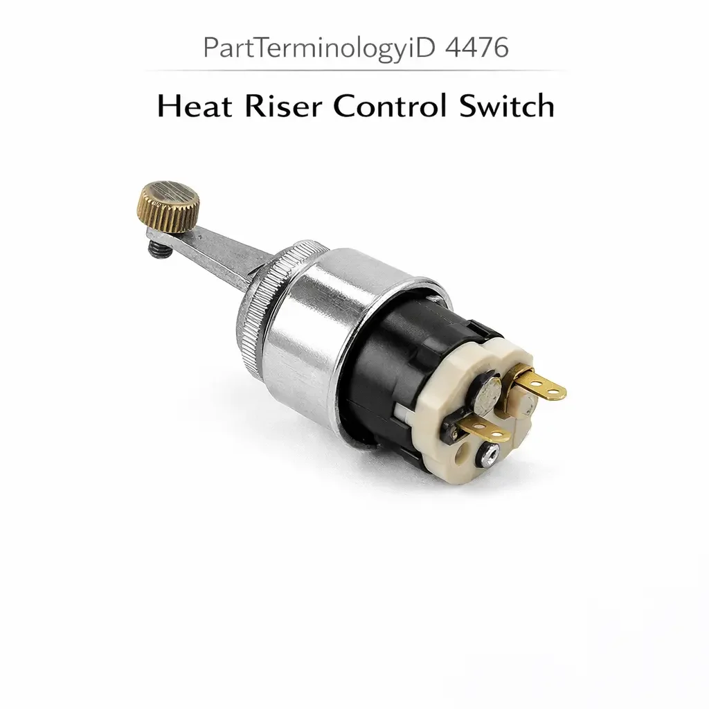
PartTerminologyID 4476, Heat Riser Control Switch, is the thermostatic vacuum switch or bi-metallic actuated valve control device mounted in the engine coolant passage, intake manifold, or air cleaner housing that governs the heat riser valve or heat control valve in the early fuel evaporation and thermostatic air cleaner system, directing heated exhaust gas or heated intake air through the intake manifold or carburetor air horn during cold-start and warm-up operation to improve fuel vaporization, prevent carburetor icing, and reduce cold-start hydrocarbon emissions by ensuring the incoming air-fuel mixture reaches a minimum temperature threshold before the heat source is removed. That definition covers the heat riser control function correctly and leaves unresolved every question that determines whether the replacement switch's temperature threshold matches the original calibration for the specific engine's warm-up profile and the heat riser system's design temperature, whether the switch controls the heat riser valve through vacuum actuation (requiring a vacuum port) or through a direct bimetallic mechanical linkage, whether the switch is a normally open vacuum type that passes vacuum to the heat riser valve actuator below the threshold or a normally closed type that blocks vacuum below the threshold and opens it above, whether the thread specification matches the coolant passage port or the air cleaner housing mounting position, and whether the switch is compatible with the specific heat riser valve's vacuum actuator specification or the thermostatic air cleaner's temperature-sensitive door mechanism.
It does not specify the temperature threshold, vacuum control type, contact or vacuum port configuration, thread specification, or heat riser system compatibility. A listing under PartTerminologyID 4476 that states only year, make, and model without threshold and vacuum routing direction cannot be evaluated by a technician replacing a failed heat riser control switch on a vehicle where the original switch passed vacuum to the heat riser valve actuator below 50 degrees Celsius (directing heated air through the intake) and blocked vacuum above 50 degrees Celsius (allowing the valve to close and direct unheated ambient air into the carburetor), and the replacement blocks vacuum below the threshold and passes it above, directing unheated ambient air into the carburetor during cold-start and heated air during warm operation, which is the exact opposite of the intended intake temperature management strategy and produces a lean cold-start stumble on every cold morning.
For sellers, PartTerminologyID 4476 occupies the same temperature-gated vacuum control category as PartTerminologyID 4308 (Engine Coolant Temperature Vacuum Control Switch) and PartTerminologyID 4352 (Distributor Thermal Vacuum Switch). The vacuum routing direction reversal is the most common and most consequential mismatch across all three PartTerminologyIDs, and the prevention requirement is the same: the routing direction must be stated in the listing title and confirmed as the primary attribute before the threshold and thread specification are evaluated.
What the Heat Riser Control Switch Does
Heat Riser System Architecture and the Intake Temperature Management Function
The heat riser system on carbureted and early throttle-body-injected engines uses exhaust heat or engine coolant heat to warm the incoming air-fuel mixture during cold-start and warm-up operation. The thermostatic air cleaner (TAC) version routes heated air from a shroud around the exhaust manifold through a duct to the air cleaner inlet, mixing it with ambient air to maintain the carburetor inlet temperature at approximately 35 to 45 degrees Celsius regardless of ambient temperature. The early fuel evaporation (EFE) heat riser version routes exhaust gases through a passage beneath the carburetor base, heating the carburetor directly from below.
Both systems use a temperature-controlled valve (the heat riser valve or the hot air blend door) that directs the heat source to the intake system when the engine is cold and bypasses it when the engine is warm. The heat riser control switch governs this valve by monitoring coolant temperature or inlet air temperature and providing the appropriate control signal (vacuum, electrical, or direct bimetallic actuation) to the valve actuator.
Temperature Threshold, Vacuum Routing Direction, and the Cold-Pass Versus Cold-Block Logic
The heat riser control switch's temperature threshold is the coolant or air temperature at which the switch changes state and alters the vacuum signal to the heat riser valve actuator. Below the threshold, the heat riser valve should be open (directing heat to the intake). Above the threshold, the heat riser valve should be closed or partially open (reducing heat to prevent intake charge over-temperature and power loss).
The vacuum routing direction determines which state corresponds to which temperature condition. A cold-pass type passes vacuum to the heat riser valve actuator when the temperature is below the threshold (cold condition), which on a vacuum-close valve design holds the valve in the heat-on position. A cold-block type blocks vacuum below the threshold, which on a vacuum-open valve design allows a spring to hold the valve in the heat-on position without vacuum assistance.
The specific routing direction required depends on the heat riser valve's actuator design (spring-open or spring-close) and the vacuum source (constant manifold vacuum or ported vacuum). Confirming the routing direction requires identifying both the switch type and the valve actuator's spring bias direction, which must be consistent for the system to operate correctly.
Thread Specification, Port Type, and Installation Position
The heat riser control switch installs in one of two positions. The coolant passage type threads into a port in the intake manifold or thermostat housing and monitors coolant temperature directly, using the same thread specifications described across adjacent PartTerminologyIDs in this series (M10 x 1.0, M12 x 1.5, or 3/8-18 NPT depending on the application). The air cleaner housing type mounts in the air cleaner housing itself, monitoring the temperature of the incoming air charge rather than the coolant, and uses a different mounting method specific to the air cleaner design.
A coolant-sensing switch installed in an air-sensing application will measure coolant temperature rather than inlet air temperature, producing a different switching timing than the original and warming the inlet air supply beyond the intended threshold because coolant typically reaches operating temperature earlier than the inlet air.
Top Return Scenarios
Scenario 1: "Routing direction reversed, unheated air during cold start, heated air during warm operation"
The replacement blocks vacuum below the threshold. The original passed vacuum below the threshold. During cold start, the heat riser valve actuator receives no vacuum and the spring positions the valve to direct unheated ambient air to the carburetor. Cold-start lean stumble occurs on every morning below 15 degrees Celsius. Above the threshold, the replacement passes vacuum and the actuator directs heated air into the carburetor, over-heating the intake charge and reducing power.
Prevention language: "Vacuum routing direction: [cold-pass, vacuum present below threshold / cold-block, vacuum absent below threshold]. Verify the routing direction against the original switch and the heat riser valve actuator's spring bias. A reversed routing direction directs unheated air to the carburetor during cold start and heated air during warm operation, producing the opposite intake temperature management from the original."
Scenario 2: "Threshold 15 degrees too high, heated air continues beyond engine warm-up, intake charge over-temperature"
The replacement threshold is 65 degrees Celsius. The original deactivated the heat riser at 50 degrees Celsius. For the 15-degree window between 50 and 65 degrees Celsius, the heat riser continues directing warmed air to the carburetor after the engine has reached normal operating temperature. The over-heated intake charge produces lean mixture symptoms and a noticeable power reduction on mild mornings.
Prevention language: "Temperature threshold: [X] degrees Celsius. The heat riser transitions to the warm-operation state above this threshold. A threshold higher than the original continues heating the intake charge beyond the designed warm-up completion point, producing over-temperature intake air and lean mixture symptoms during normal operation."
Scenario 3: "Coolant-sensing switch installed in air-sensing application, switch responds to coolant rather than inlet air temperature"
The original switch was an air-sensing type mounted in the air cleaner housing. The replacement is a coolant-sensing type requiring a threaded coolant passage port. The air cleaner housing has no threaded port for a coolant-sensing switch, requiring a bracket adaptation, and the coolant reaches operating temperature 3 to 5 minutes before the inlet air reaches the heat riser's intended switching temperature, causing the heat riser to deactivate prematurely on cold mornings before the inlet air has warmed sufficiently.
Prevention language: "Sensing type: [coolant temperature sensing, threaded coolant passage installation / intake air temperature sensing, air cleaner housing installation]. Verify the sensing type against the original switch. Coolant-sensing and air-sensing types respond to different temperature signals and produce different switching timing on the same engine."
Core Listing Attributes for PartTerminologyID 4476
PartTerminologyID: 4476
Component: Heat Riser Control Switch
Temperature threshold in degrees Celsius (mandatory, in title)
Vacuum routing direction: cold-pass or cold-block (mandatory, in title)
Sensing type: coolant temperature or intake air temperature (mandatory)
Thread specification for coolant-sensing types: diameter, pitch, thread form (mandatory)
Mounting specification for air-sensing types: air cleaner housing clip or bracket type (mandatory)
Vacuum port count and fitting size (mandatory)
Sealing method: crush washer, O-ring, or NPT thread sealant (mandatory for coolant-sensing types)
Heat riser system type: thermostatic air cleaner or EFE exhaust heat riser (recommended)
Year/make/model/engine
FAQ (Buyer Language)
How do I confirm the correct vacuum routing direction for my heat riser system?
With the engine cold, apply a vacuum gauge to the outlet port of the original switch. If vacuum is present at the outlet port at cold engine temperature, the switch is a cold-pass type. If vacuum is absent at the outlet port at cold temperature, the switch is a cold-block type. Confirm this matches the replacement switch's stated routing direction before installation.
Can I test the original switch before replacing it?
Yes. Place the sensing element in water heated to just above the rated threshold while monitoring the outlet port with a vacuum gauge and a vacuum source applied to the inlet port. The switch should change its vacuum routing state within a few degrees of the rated threshold. A switch that does not change state at the rated temperature has failed and requires replacement.
Related PartTerminologyIDs
Engine Coolant Temperature Vacuum Control Switch (PartTerminologyID 4308): controls vacuum to EGR and distributor advance circuits; the heat riser control switch controls vacuum to the intake air heating valve; both are coolant passage vacuum switches but for different controlled circuits; confirm the switch's vacuum hose destination before ordering either component
Early Fuel Evaporation (EFE) Heater Temperature Switch (PartTerminologyID 4372): controls the electrical EFE heater circuit; the heat riser control switch controls the vacuum-actuated EFE heat riser valve; both govern intake mixture heating but through different mechanisms at different circuit positions
Status in New Databases
PIES/PCdb: PartTerminologyID 4476, Heat Riser Control Switch
PIES 8.0 / PCdb 2.0: No change in PartTerminologyID or terminology label
Final Take for PartTerminologyID 4476
Heat Riser Control Switch (PartTerminologyID 4476) is the intake temperature management PartTerminologyID where vacuum routing direction and temperature threshold together define the precise warm-up window during which the heat riser contributes to fuel vaporization, and a routing direction reversal produces the opposite intake temperature management from the original on every cold-start event. State the routing direction in the title. State the threshold in the title. State the sensing type. State the thread specification for coolant-sensing types. For PartTerminologyID 4476, vacuum routing direction, temperature threshold, and sensing type are the three attributes that prevent the three most common return scenarios in the heat riser control switch buyer population.