Headlight Switch (PartTerminologyID 4472): Circuit Architecture, Integrated Function Coverage, and Body Control Module Compatibility
Written by Arthur Simitian | PartsAdvisory
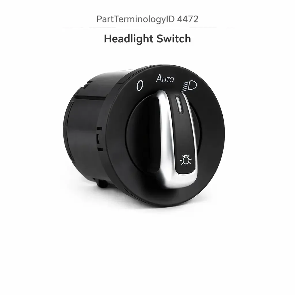
PartTerminologyID 4472, Headlight Switch, is the driver-operated control device that activates the vehicle's exterior lighting system including the headlamps, parking lamps, tail lamps, license plate lamp, and instrument panel illumination, and in many applications also governs the daytime running lamp circuit, the fog lamp circuit, the dome light override position, the instrument panel dimmer function, and the automatic headlamp activation input, communicating the driver's lighting commands to the headlamp relay, the body control module, or the exterior lighting control module through direct contact closure, a switched ground input, or a serial bus digital command depending on the vehicle's exterior lighting architecture. That definition covers the exterior lighting activation function correctly and leaves unresolved every question that determines whether the replacement switch matches the original's circuit architecture and integrated function coverage, whether the connector pin count and terminal assignment match the harness at the instrument panel or steering column position, whether the switch is a rotary type with discrete off, parking, and headlamp positions or a push-pull type or a stalk-mounted rotary ring segment, whether the replacement includes the same set of integrated functions as the original including instrument panel dimmer output, dome light override position, fog lamp activation position, automatic mode position, and flash-to-pass or pull-to-pass function where applicable, whether the switch is compatible with the BCM's lighting input signal type on vehicles where the BCM manages the headlamp relay through software rather than through hardware contacts in the switch, whether the replacement requires programming after installation on vehicles with serial bus exterior lighting control, whether the switch is rated for the headlamp relay coil current or the full headlamp circuit current depending on the circuit architecture, whether the replacement covers a halogen headlamp circuit or an HID or LED headlamp circuit with different relay and current characteristics, and whether the switch includes an auto-headlamp position that activates the ambient light sensor input to the BCM for automatic headlamp control.
It does not specify the circuit architecture, integrated function coverage, connector pin count, switch type, BCM input compatibility, programming requirement, headlamp technology compatibility, or auto-mode input. A listing under PartTerminologyID 4472 that states only year, make, and model without circuit architecture and integrated function coverage cannot be evaluated by a technician replacing a failed headlight switch on a vehicle where the original switch was an eight-position rotary assembly with off, parking lamp, headlamp, auto, fog, and instrument dimmer positions each with dedicated circuit outputs and an eighteen-pin connector, and the replacement is a five-position rotary from the base lighting trim covering only off, parking, and headlamp positions with a ten-pin connector, leaving the auto mode input, fog lamp activation, instrument dimmer, and dome light override permanently uncontrolled from the headlight switch position.
For sellers, PartTerminologyID 4472 is the exterior lighting PartTerminologyID with the broadest integrated function set of any lighting control component, because the headlight switch on many modern vehicles is not merely a headlamp on-off device but the primary exterior lighting control assembly integrating headlamp on-off, parking lamp, tail lamp, instrument dimmer, fog lamp, automatic headlamp mode, daytime running lamp override, flash-to-pass, and in some stalk configurations the turn signal and high beam functions. The consequence of a function coverage mismatch is proportional to which functions are missing: a switch missing the auto mode leaves the driver without automatic headlamp control but retains manual activation, whereas a switch missing the fog lamp output leaves the fog lights permanently uncontrolled from the primary switch position. Both are correct installation errors that pass a basic headlamp function test but fail the full function verification.
What the Headlight Switch Does
Exterior Lighting Architecture and the Relay versus BCM Control Distinction
The headlight switch operates within one of three circuit architectures that determine the switch's function as either a hardware power control device, a BCM input device, or a digital command transmitter.
In the direct relay architecture used on vehicles through the mid-1990s, the headlight switch carries or routes the headlamp circuit supply current directly through its contacts to the headlamp relay coils. The parking lamp contacts carry the parking circuit current to the tail, license plate, side marker, and instrument illumination circuits directly. The switch in this architecture must have contacts rated for the current of each circuit it controls, and the switch body dissipates heat from the resistive losses at the contact surfaces. A headlamp relay coil draws approximately 0.2 to 0.5 amperes, while the parking lamp contacts on a fully incandescent system may carry 5 to 8 amperes directly.
In the BCM input architecture used on most vehicles from the late 1990s onward, the headlight switch carries only low-current switched ground signals to the BCM's lighting input pins. The BCM receives these inputs and activates the headlamp, parking lamp, tail lamp, and instrument illumination circuits through its own internal relay outputs or transistor output stages. The switch contacts carry only the BCM input signal current (1 to 10 milliamperes per input), and the contact current rating is not a primary specification concern. The signal type and pin assignment are the governing specifications.
In the serial bus architecture used on premium and modern vehicles, the headlight switch contains a microcontroller that transmits lighting command messages on the CAN bus or LIN bus network. The exterior lighting control module receives these messages and manages all lighting circuit outputs. The switch carries no circuit current of any kind and its specifications are the network message identifiers, the programming requirement, and the physical mounting geometry.
Integrated Functions and the Position Coverage Requirement
The headlight switch assembly on modern vehicles integrates multiple lighting control functions into a single rotary or multi-detent control. The function positions available in the original switch assembly define the complete lighting control capability accessible from the headlight switch, and a replacement must cover all of these positions to restore full lighting control.
The standard minimum function set for a domestic headlight switch includes three positions: off, parking lamps (tail, side marker, license plate, and instrument illumination active with headlamps off), and headlamps on (all parking lamp functions plus headlamps). This three-position minimum is the base-trim configuration on most domestic platforms.
Mid-trim and luxury trim configurations add positions including auto mode (ambient light sensor governs headlamp activation automatically), fog lamp activation (typically a rotary detent beyond the headlamp position), and a dome light override detent at the end of the off direction (fully counterclockwise activates the dome light directly). The instrument panel dimmer function is typically implemented as a continuous variable adjustment integrated into the headlight switch knob's rotation between the off and parking lamp positions, or as a separate concentric ring on the switch knob.
A replacement that covers fewer positions than the original leaves the omitted functions inaccessible from the headlight switch. If the fog lamp circuit can only be activated from the headlight switch's fog position (no separate fog lamp switch present), a replacement without the fog position leaves the fog lights permanently uncontrolled. If the auto mode is the preferred headlamp control mode for the owner, a replacement without the auto position forces manual headlamp management. If the instrument dimmer is integrated into the switch and the replacement does not include the dimmer function, the instrument panel illumination runs at a fixed brightness unresponsive to the dimmer input.
Auto Mode and the Ambient Light Sensor Integration
The automatic headlamp mode (auto mode) activates the headlamps, tail lamps, and instrument illumination automatically in response to the ambient light sensor mounted in the instrument cluster or the base of the windshield. When the switch is in the auto position, the BCM receives the auto mode signal and uses the ambient light sensor output to determine when to activate and deactivate the exterior lighting, providing headlamps in tunnels, at dusk and dawn, and in precipitation conditions without manual switch input.
The auto mode position in the headlight switch sends a specific signal to the BCM (typically a distinct resistance value on a resistance-encoded input or a specific contact closure on a dedicated auto mode input pin) that the BCM interprets as an auto mode command. The BCM then polls the ambient light sensor and activates or deactivates the headlamp relay based on the sensor output.
A replacement switch without the auto mode position on a vehicle where the BCM has ambient light sensor capability and the driver relies on automatic headlamp activation removes a convenience function that the original switch provided. More critically, on some markets where automatic headlamp activation in low-light conditions is required by law, a replacement without auto mode may produce a regulatory compliance issue if the driver does not manually activate the headlamps in conditions where the original switch would have activated them automatically.
Instrument Panel Dimmer Integration and the Output Type
The instrument panel dimmer function integrated into the headlight switch produces a variable output (typically a variable resistance, a variable voltage, or a PWM signal) that the instrument panel lighting circuit uses to adjust the brightness of the instrument cluster backlighting, HVAC panel illumination, and other panel controls. The dimmer output type must match the instrument panel lighting circuit's input specification, following the same conventions described in PartTerminologyID 4340 (Dimmer Switch).
A replacement headlight switch with a dimmer output range that differs from the original produces incorrect instrument panel brightness at specific rotary positions. A switch with a narrower dimmer range limits the maximum and minimum achievable brightness. A switch with a reversed dimmer range (maximum output at the parking lamp detent and minimum output at the headlamp detent) inverts the panel brightness as the switch is rotated from parking to headlamp position.
On vehicles where the headlight switch contains the sole dimmer control for the instrument panel illumination, a replacement without the dimmer function leaves the instrument panel at a fixed brightness that cannot be adjusted, affecting night driving comfort across the entire service life of the vehicle.
Flash-to-Pass and Pull-to-Activate Functions
Many headlight switches incorporate a flash-to-pass function that briefly activates the high beams when the switch is pulled forward or rearward from the headlamp-on position, providing a momentary high beam signal for traffic warning without requiring the high beam lock engagement. On stalk-integrated configurations, the flash-to-pass is a stalk pull function. On rotary headlight switch configurations, the flash-to-pass may be a spring-loaded pull-toward-driver motion on the switch knob or a secondary switch position integrated into the switch body.
The headlamp pull-to-activate function (pulling the stalk to activate the headlamps in the first pull position, with a second pull activating the high beams) is the standard on many European and Asian market vehicles where the headlamp switch is a pull-out function rather than a rotary position. A replacement switch that uses a rotary on position instead of a pull-out activation changes the driver's headlamp activation mechanism entirely.
Both the flash-to-pass and the pull-to-activate function must be preserved in the replacement to match the original switch's operational interface.
HID and LED Headlamp Circuit Compatibility
Vehicles equipped with high-intensity discharge (HID) or LED headlamp systems use different relay and module configurations than halogen headlamp systems. HID headlamp systems require a ballast module that provides the high-voltage ignition pulse needed to initiate the arc in the HID bulb, and the headlamp relay architecture for HID systems typically includes a dedicated ballast control circuit that the headlight switch or BCM activates separately from the halogen relay circuit.
LED headlamp systems use an LED driver module that receives the headlamp activation signal from the BCM or the headlight switch and manages the LED array's current supply. Some LED headlamp systems require a specific activation signal type from the headlight switch that differs from the halogen circuit's simple relay contact closure.
A replacement headlight switch specified for a halogen circuit installed on an HID or LED equipped vehicle will not include the ballast control or LED driver activation output, leaving the headlamp system unable to complete its startup sequence even if the headlamp relay itself is energized. The headlamp technology (halogen, HID, or LED) must be stated as a mandatory attribute for all headlight switch listings on vehicles where the headlamp technology varies by trim level.
Daytime Running Lamp Circuit and the Override Function
Daytime running lamps (DRL) are low-intensity forward-facing lamps or reduced-intensity headlamps that activate automatically when the vehicle is running without requiring the headlight switch to be in any specific position. The DRL function is managed by the BCM and is independent of the headlight switch's manual control. However, some headlight switch designs include a DRL override or cancel function that allows the driver to disable the DRL system when required (for example, in drive-in movie theaters or car wash facilities).
A replacement switch without the DRL override function in an application that includes it removes the driver's ability to cancel the DRL. This is a minor function loss in most circumstances but is relevant in the specific situations where DRL cancellation is needed. The DRL override function and its circuit pin must be confirmed when replacing a headlight switch on vehicles where the DRL override is a documented feature.
Multifunction Stalk Integration and the Complete Assembly Requirement
Stalk-integrated headlight function and the full assembly replacement scope
On many European and some domestic vehicles, the headlight activation function is integrated into a multifunction stalk on the left side of the steering column alongside the turn signal, high beam, flash-to-pass, and in some configurations the wiper and washer functions. The headlight positions on a stalk-integrated configuration are typically a rotary ring at the end of the stalk or a pull-and-rotate mechanism, with separate detents for off, parking, and headlamps.
Replacing the headlight function on a stalk-integrated vehicle requires replacing the complete stalk assembly, not a standalone switch component. A listing for a stalk-integrated headlight switch must state that the replacement is a complete stalk assembly and list all integrated functions.
Rotary headlight switch with concentric dimmer ring
Some rotary headlight switches use a concentric control architecture where the outer ring of the switch knob rotates to select the headlamp position (off, parking, headlamp, auto, fog) and the inner portion or a concentric ring rotates independently to adjust the instrument panel dimmer output. The concentric dimmer ring operates through a separate resistive track or potentiometer concentric with the main switch shaft, and the two controls produce independent outputs to separate circuit pins.
A replacement for a concentric dimmer ring assembly must match both the outer ring's position detent configuration and the inner ring's dimmer output specification. A replacement without the concentric dimmer function leaves the instrument dimmer permanently at one output level regardless of the inner ring's position.
Why This Part Generates Returns
Buyers return headlight switches because the replacement covers five positions and the original covers eight, leaving auto mode, fog lamp, and dome light override permanently unavailable from the headlight switch; the circuit architecture is a direct relay type and the application uses a BCM input circuit, overloading the BCM input pull-up and producing a BCM input fault on the headlamp circuit; the connector is a ten-pin type and the harness at the instrument panel has an eighteen-pin connector covering the full function set including auto mode, DRL override, fog lamp, dome light, and dimmer outputs that the ten-pin replacement leaves unconnected; the instrument dimmer output range in the replacement is 0 to 3.5 volts and the instrument panel is calibrated for a 0 to 5 volt range, limiting all instrument brightness to 70 percent of the original maximum regardless of dimmer rotation; the switch requires CAN bus registration and the listing does not disclose this, leaving the headlamp system non-functional after installation; the replacement is specified for a halogen headlamp circuit and the vehicle has HID headlamps where the switch must also activate the ballast control circuit absent in the halogen replacement; the switch is a standalone rotary type and the application uses a stalk-integrated headlight function requiring a complete column stalk assembly; and the flash-to-pass mechanism in the replacement requires a push-forward action where the original used a pull-toward-driver action, reversing the driver's learned headlamp flash activation motion.
Top Return Scenarios
Scenario 1: "Five-position replacement in eight-position application, auto mode, fog, and dome override absent"
The buyer replaces the headlight switch on a vehicle with an eight-position rotary assembly. The listing covers the vehicle without specifying position count. The delivered switch has five positions. After installation, the headlamp, parking lamp, and instrument dimmer functions work correctly. The auto mode input to the BCM is absent: the BCM defaults to headlamps on based on the last stored state because it receives no auto mode command and no off command simultaneously. The fog lamp circuit cannot be activated from the switch. The dome light override position is absent.
Prevention language: "Switch position count: [X] positions covering [off, parking lamp, headlamp, auto mode, fog lamp, dome light override, and dimmer range as applicable]. Verify the position count and function coverage against the original switch. A replacement with fewer positions than the original leaves the omitted functions permanently inaccessible from the headlight switch."
Scenario 2: "Direct relay switch in BCM input circuit, BCM headlamp input pull-up overloaded"
The buyer replaces the headlight switch on a BCM-managed exterior lighting system. The listing does not specify circuit architecture. The replacement is a direct relay type from a pre-BCM variant of the platform. After installation, the headlamps activate when the switch is rotated to the headlamp position. However, the BCM's headlamp input pull-up circuit is overloaded by the relay coil resistance the direct relay switch presents. After several weeks, the BCM's headlamp input detection becomes erratic and the BCM stores an intermittent headlamp circuit fault.
Prevention language: "Circuit architecture: [direct relay circuit, switch carries relay coil or lamp circuit current / BCM switched ground input, switch carries milliamp signal only / serial bus digital command]. Verify the circuit architecture before ordering. A direct relay switch in a BCM input circuit overloads the BCM input pull-up through the relay coil resistance and will degrade the BCM's headlamp input detection over time."
Scenario 3: "Halogen switch in HID application, ballast control circuit absent, HID lamps do not start"
The buyer installs the replacement headlight switch on a vehicle with factory HID headlamps. The headlamp relay is energized and the relay closes, but the HID lamps do not produce light. The HID ballast modules require a separate activation signal from the headlight switch or BCM to initiate the high-voltage arc ignition sequence. The halogen replacement does not include the ballast activation output pin. The relay energizes the low-voltage supply to the ballasts but the ignition pulse is never triggered because the activation input is absent.
Prevention language: "Headlamp technology: [halogen / HID, includes ballast activation output / LED, includes LED driver activation output]. Verify the headlamp technology before ordering. HID and LED headlamp systems require additional activation outputs beyond the headlamp relay closure that are absent in halogen-specified replacements. Installing a halogen switch on an HID or LED system will energize the relay but prevent headlamp startup."
Scenario 4: "CAN bus switch requires registration, listed as plug-and-play, headlamps non-functional after installation"
The buyer installs the replacement on a vehicle with CAN bus exterior lighting control. No headlamp activation occurs on any switch position after installation. The listing states no programming is required. The exterior lighting module requires the new switch's CAN node address to be registered in its memory before it accepts lighting commands from the switch. Without registration, the module receives no recognized commands and maintains the last stored lighting state (off at installation).
Prevention language: "Post-installation programming: [not required, self-initializing / required, exterior lighting module registration with [scan tool type]]. Failure to complete registration after installation results in no headlamp response on any switch position. Headlamp non-function after installation on a CAN bus lighting system is typically caused by missing switch registration rather than a defective switch."
Scenario 5: "Ten-pin replacement in eighteen-pin harness, auto mode and fog lamp circuits unconnected"
The buyer replaces the headlight switch. The headlamp, parking lamp, and instrument dimmer functions all work correctly. The vehicle's ambient light sensor stops governing headlamp activation because the auto mode input pin is absent in the ten-pin connector. The fog lamp circuit is permanently inactive. The BCM logs a fault for the missing auto mode input and stores a fog circuit fault for the open input at the pin position corresponding to fog activation.
Prevention language: "Connector pin count: [X] pins covering [off, parking, headlamp, auto mode, fog lamp, DRL override, dome light override, dimmer output, ground, and supply as applicable]. Verify pin count and function mapping against the original harness. A replacement with fewer pins than the original leaves active BCM input circuits open, generating fault codes and disabling the functions associated with the absent pins."
Scenario 6: "Instrument dimmer output range 0 to 3.5 volts, instrument panel calibrated for 0 to 5 volts, maximum brightness limited to 70 percent"
The buyer installs the replacement switch. All headlamp positions function correctly. The instrument panel illumination is noticeably dimmer than before the replacement at all dimmer settings. At the maximum dimmer rotation, the instrument panel reaches approximately 70 percent of the brightness level the original produced at its maximum position. The replacement's dimmer output reaches 3.5 volts at maximum rotation where the instrument panel circuit requires a 5-volt maximum for full brightness.
Prevention language: "Instrument dimmer output range: [minimum X volts to maximum X volts] or [minimum X ohms to maximum X ohms]. Verify the dimmer output range against the instrument panel lighting circuit's input specification. A replacement with a lower maximum output than the original limits the instrument panel to a reduced maximum brightness that cannot be increased regardless of dimmer rotation."
Scenario 7: "Standalone rotary switch in stalk-integrated application, no installation path"
The buyer's stalk-integrated headlight ring segment has broken detents allowing the switch to slip past the headlamp position. The listing covers the vehicle under the headlight switch PartTerminologyID without noting stalk integration. The delivered unit is a standalone rotary switch designed for an instrument panel cutout mounting position. The vehicle has no instrument panel cutout for a headlight switch and no harness connector at an instrument panel position for headlamp control. The stalk assembly must be replaced.
Prevention language: "Switch type: [standalone rotary instrument panel switch / stalk-integrated headlight ring segment, complete stalk assembly required]. This application integrates the headlight function into the steering column stalk. The headlight function cannot be replaced independently. The complete stalk assembly is the replacement unit."
Scenario 8: "Flash-to-pass mechanism reversed, push-forward where original was pull-toward-driver"
The buyer installs the replacement rotary headlight switch. All rotary position functions work correctly. When the driver attempts to use the flash-to-pass function on the highway, pressing the switch forward produces no result. The flash-to-pass activation in the replacement requires a pull-toward-driver motion. The original switch used a push-forward motion. The driver's learned muscle memory for flash-to-pass produces no response in the replacement's mechanism, requiring a full relearning of the activation direction.
Prevention language: "Flash-to-pass activation direction: [pull toward driver / push forward / push sideways]. Verify the flash-to-pass activation direction against the original switch. A reversed activation direction requires the driver to relearn the flash-to-pass mechanism. During the relearning period, flash-to-pass activations may be missed or delayed on the highway."
Core Listing Attributes for PartTerminologyID 4472
PartTerminologyID: 4472
Component: Headlight Switch
Circuit architecture: direct relay, BCM switched ground input, or serial bus digital command (mandatory, in title)
Switch type: standalone rotary, push-pull, rocker, or stalk-integrated with complete assembly note (mandatory, in title)
Position count with all positions listed (mandatory)
Function coverage: all integrated functions including dimmer, auto mode, fog, DRL override, dome override, flash-to-pass (mandatory)
Connector pin count with function mapping for each pin (mandatory)
Contact current rating for direct relay circuit types (mandatory)
Instrument dimmer output range: voltage or resistance minimum and maximum (mandatory)
Auto mode input: included or not included (mandatory)
Headlamp technology compatibility: halogen, HID with ballast activation output, or LED with driver activation output (mandatory)
Flash-to-pass activation direction: pull, push, or lateral (mandatory)
Post-installation programming requirement: none or tool and procedure required (mandatory for serial bus types)
Knob or stalk interface for replacement knob fitment where applicable (mandatory)
Year/make/model/submodel/trim/equipment level/market specification
Note for trim levels where position count and connector pin count differ
Note for production date range where circuit architecture changed
Note for market variants where auto mode is required for lighting law compliance
Note for stalk-integrated applications where complete stalk assembly is the replacement unit
Catalog Checklist for ACES/PIES Teams
PartTerminologyID = 4472
Require circuit architecture in title: direct relay, BCM input, or serial bus (mandatory)
Require switch type in title: standalone or stalk-integrated (mandatory)
Require position count with all positions listed (mandatory)
Require complete function coverage list including dimmer, auto, fog, DRL, dome, flash-to-pass (mandatory)
Require connector pin count with function mapping (mandatory)
Require contact current rating for direct relay types (mandatory)
Require instrument dimmer output range (mandatory)
Require headlamp technology compatibility: halogen, HID, or LED (mandatory)
Require flash-to-pass activation direction (mandatory)
Require programming disclosure for serial bus types (mandatory)
Prevent position count omission: a five-position replacement in an eight-position application leaves auto mode, fog, and dome override permanently absent; position count and full function coverage must be in every listing
Prevent circuit architecture omission: a direct relay switch in a BCM input circuit overloads the BCM input pull-up and generates a headlamp circuit fault over time; architecture must be confirmed as the first compatibility check
Prevent headlamp technology omission: a halogen switch in an HID application energizes the relay but does not trigger the ballast startup sequence; technology must be confirmed for all trim levels where HID or LED headlamps are available
Prevent dimmer output range omission: a replacement with a lower maximum dimmer output limits instrument brightness permanently; output range must be stated and verified against the instrument panel circuit
Prevent stalk integration omission: a standalone switch has no installation path on a stalk-integrated application; switch type must be in the title
Prevent programming omission: a CAN bus switch listed as plug-and-play leaves the headlamp system non-functional after installation; programming requirement must be disclosed with scan tool specification
Differentiate from Dimmer Switch (PartTerminologyID 4340): the dimmer switch is a standalone instrument panel brightness control on vehicles where the dimmer is separate from the headlight switch; on vehicles where the dimmer is integrated into the headlight switch knob, PartTerminologyID 4472 covers the complete assembly including the dimmer function
Differentiate from Fog Light Switch (PartTerminologyID 4408): the fog light switch is a standalone fog lamp control on vehicles where the fog function is separate from the headlight switch; on vehicles where the fog position is integrated into the headlight switch rotary detent, PartTerminologyID 4472 covers the complete assembly including the fog function
Differentiate from Daytime Running Light Module (if cataloged): the DRL module manages the daytime running lamp circuit; the headlight switch's DRL override position provides the driver's ability to cancel the DRL function; both affect the DRL circuit but at different positions with different failure symptoms
FAQ (Buyer Language)
How do I identify all the positions on my headlight switch before ordering a replacement?
Turn the switch knob or stalk ring slowly from the fully counterclockwise (off) position to the fully clockwise (maximum) position, noting each detent click. Count the detents: each detent is a functional position. Identify each position by observing which exterior lights activate at each detent from the outside of the vehicle, and whether the instrument panel illumination changes brightness between the off and parking detent (indicating an integrated dimmer range). If the fully counterclockwise position activates the dome light, that is an integrated dome light override position.
My headlights work but the instrument panel is too dim after replacing the switch. What happened?
Instrument panel dimness after headlight switch replacement indicates a dimmer output range mismatch. The replacement switch's maximum dimmer output is below the instrument panel circuit's full-brightness threshold. Confirm the original switch's dimmer output range from the factory service manual or the original part specification and compare it to the replacement's stated range. A dimmer output that is too low cannot produce full instrument brightness at any rotary position.
Can I use a base-trim headlight switch on my higher-trim vehicle if the connector physically fits?
Only if the base-trim switch includes all the positions and functions present in the original higher-trim switch. Physical connector compatibility does not confirm function coverage compatibility. Higher-trim switches have more positions and more active circuit pins than base-trim switches. Installing a base-trim switch on a higher-trim vehicle leaves every function present in the higher trim but absent in the base trim permanently inaccessible.
My HID headlamps come on briefly then shut off immediately after replacing the headlight switch. What is happening?
HID headlamps that ignite and immediately extinguish is the characteristic symptom of a ballast that successfully fires its ignition pulse but then does not receive the sustained activation signal needed to maintain the arc. This indicates the replacement switch includes a headlamp relay output but does not include the ballast activation output that the original switch provided. The relay energization triggers the ballast's initial arc attempt but the ballast shuts down because its activation input is absent. Confirm whether the original switch included a dedicated ballast activation output pin.
Does the auto mode on the headlight switch require a separate ambient light sensor?
Yes. The auto mode position on the headlight switch tells the BCM to use the ambient light sensor input to govern headlamp activation automatically. The ambient light sensor is a separate component mounted in the instrument cluster or at the base of the windshield. If the ambient light sensor is absent or failed, the auto mode position will not produce automatic headlamp activation regardless of the switch's function. Auto mode requires both the switch's auto position signal to the BCM and a functional ambient light sensor connected to the BCM's sensor input.
How do I confirm whether my vehicle uses direct relay or BCM-managed headlamp control?
Confirm the wire gauge at the headlight switch connector. A multi-conductor connector with one or two heavier wires (14 to 16 AWG) alongside lighter signal wires indicates a direct relay circuit where the switch carries relay coil or lamp circuit current. A connector with all light-gauge wires (18 to 22 AWG throughout) indicates a BCM input or serial bus circuit. On any vehicle produced after 1998 with a BCM listed in the service manual's electrical component location, assume BCM input architecture and confirm the specific circuit type before ordering.
Related PartTerminologyIDs
Dimmer Switch (PartTerminologyID 4340): the standalone instrument panel dimmer on vehicles where the dimmer is a separate switch from the headlight switch; on vehicles where the dimmer is integrated into the headlight switch, PartTerminologyID 4472 covers both functions in the same assembly
Fog Light Switch (PartTerminologyID 4408): the standalone fog lamp switch on vehicles where the fog function is separate from the headlight switch; on vehicles where the fog position is a detent on the headlight switch, PartTerminologyID 4472 covers both functions
Body Control Module (if cataloged): the module managing headlamp relay outputs on BCM-integrated systems; a BCM that does not activate the headlamp relay despite receiving the correct switch input indicates a BCM output fault; confirm BCM input detection with a scan tool before replacing the switch on a no-headlamp complaint
Daytime Running Light Module (if cataloged): the module managing the DRL circuit; a headlight switch with a DRL override position can cancel the DRL; if the DRL continues operating after the override position is engaged, the issue is in the DRL module's response to the override signal rather than a failed headlight switch
Ambient Light Sensor (if cataloged): the sensor whose input the BCM uses in auto mode; a headlight switch in auto mode that does not produce automatic headlamp activation confirms a failed sensor or sensor input rather than a failed switch auto mode output
Status in New Databases
PIES/PCdb: PartTerminologyID 4472, Headlight Switch
PIES 8.0 / PCdb 2.0: No change in PartTerminologyID or terminology label
Final Take for PartTerminologyID 4472
Headlight Switch (PartTerminologyID 4472) is the exterior lighting PartTerminologyID with the broadest integrated function set requiring explicit position-by-position coverage confirmation, because a replacement with fewer positions than the original passes a basic headlamp function test (headlamps on, headlamps off) while silently removing auto mode, fog lamp, dome override, DRL cancel, and instrument dimmer functions that the driver depended on before the replacement. The circuit architecture is the attribute with the most immediate BCM damage consequence because a direct relay switch in a BCM input circuit overloads the pull-up through the relay coil resistance. The headlamp technology is the attribute with the most visually confusing failure consequence because a halogen switch on an HID system energizes the relay and causes the ballast to attempt an arc ignition without the sustained activation signal, producing headlamps that briefly flicker before extinguishing.
State the circuit architecture in the title. State the switch type in the title. State all positions by name. State the complete function coverage list. State the connector pin count with function mapping. State the instrument dimmer output range. State the headlamp technology compatibility. State the auto mode and flash-to-pass specifications. State the programming requirement. For PartTerminologyID 4472, position count with complete function coverage, circuit architecture, and headlamp technology compatibility are the three attributes that prevent the three most consequential and most common return scenarios in the headlight switch buyer population.