Hazard Warning Switch (PartTerminologyID 4468): Circuit Architecture, BCM Integration, and Multi-Function Stalk Configuration
Written by Arthur Simitian | PartsAdvisory
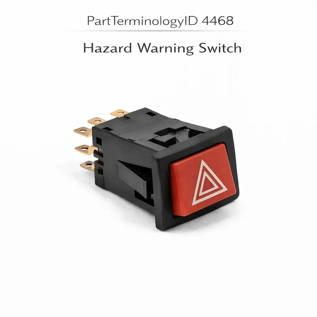
PartTerminologyID 4468, Hazard Warning Switch, is the driver-operated switch that activates the vehicle's hazard warning system, commanding all four turn signal lamps to flash simultaneously at a rate between 60 and 120 cycles per minute as required by FMVSS 108 to provide an emergency warning signal to other road users when the vehicle is disabled, performing an emergency maneuver, or otherwise requires immediate visual alerting, and in modern vehicles sending the hazard activation command to the body control module, the exterior lighting control module, or the turn signal and hazard flasher module through a direct relay circuit, a switched ground input, or a serial bus digital command depending on the vehicle's exterior lighting control architecture. That definition covers the hazard warning activation function correctly and leaves unresolved every question that determines whether the replacement switch is compatible with the vehicle's hazard circuit architecture (direct flasher relay, BCM-managed, or steering column stalk-integrated), whether the switch connector pin count and terminal assignment match the harness at the instrument panel, center stack, or steering column position, whether the switch is a standalone push-button or rocker type or a combined turn signal and hazard stalk that integrates the hazard function with the turn signal activation, whether the switch includes an integrated indicator lamp or LED element that illuminates when the hazard circuit is active, whether the switch body profile and mounting geometry match the instrument panel cutout or stalk housing at the installation position, whether the replacement is compatible with the BCM's hazard input signal type on vehicles where the BCM receives a switched ground request and manages the four-way flash through its own output stage, whether the replacement requires programming or module initialization after installation on vehicles where the BCM or exterior lighting module must register the new switch before accepting its commands, whether the switch is compatible with the crash detection system that automatically activates the hazard lights on airbag deployment, whether the switch covers the stop-then-go traffic assistant function on some European and Asian market vehicles where the hazard lamps flash a defined sequence to alert following traffic when the vehicle brakes to a complete stop from highway speed, and whether the replacement includes the SOS or emergency call function integration present in some telematics-equipped vehicles where pressing the hazard switch for an extended duration activates an emergency call to the vehicle's telematics system.
It does not specify the circuit architecture, connector pin count, switch type, indicator lamp configuration, BCM input compatibility, programming requirement, crash detection integration, stop-then-go function, or SOS integration. A listing under PartTerminologyID 4468 that states only year, make, and model without circuit architecture and BCM input compatibility cannot be evaluated by a technician replacing a failed hazard warning switch on a vehicle where the original switch sent a switched ground signal to the BCM's hazard input pin and the BCM managed the four-way flash relay through a timed software output, and the replacement is a direct relay switch that connects the hazard flasher relay coil supply directly to battery voltage through the switch contacts, bypassing the BCM's hazard management entirely and producing a hazard system that activates the lamps but does not respect the BCM's automatic hazard activation on airbag deployment, does not integrate with the vehicle speed sensor input that the BCM uses to enforce hazard activation conditions, and does not provide the automatic hazard cancellation on vehicle restart that prevents the driver from driving away with the hazard lights on.
For sellers, PartTerminologyID 4468 is the exterior safety lighting PartTerminologyID with the most direct FMVSS 108 consequence of any driver-operated switch, because the hazard warning system is the primary four-way simultaneous flash emergency signal mandated by federal regulation and a non-functional hazard switch leaves the vehicle without this regulated emergency capability. It is also the PartTerminologyID where the crash detection integration and automatic activation functions are the most frequently missed secondary attributes, because a switch that manually activates the hazard circuit correctly but does not include the BCM input path used for automatic crash-triggered activation provides only partial hazard system functionality. The driver cannot activate the hazards manually when the system is most critical, but a collision event that triggers airbag deployment will not automatically activate the hazards as the vehicle manufacturer designed.
What the Hazard Warning Switch Does
FMVSS 108 Four-Way Simultaneous Flash Mandate and the Regulatory Consequence of Switch Failure
FMVSS 108 requires all passenger vehicles sold in the United States to be equipped with a hazard warning signal system that activates all four turn signal lamps simultaneously at a flash rate between 60 and 120 cycles per minute when the hazard warning switch is engaged. The simultaneous activation of all four lamps is the defining characteristic that distinguishes the hazard warning signal from the directional turn signal, and the availability of this function at all times the vehicle is accessible is implicitly required by the standard.
A failed hazard warning switch that prevents manual hazard activation is an FMVSS 108 compliance issue and a direct safety deficiency. Unlike a failed turn signal switch that affects only directional signaling, a failed hazard switch removes the emergency warning capability that a stranded or disabled vehicle depends on to alert approaching traffic. The hazard warning switch is one of the few vehicle switches whose failure can directly expose the vehicle and its occupants to the risk of being struck by an approaching vehicle that has no visual warning of the stationary or slow-moving obstacle ahead.
The buyer replacing a hazard warning switch has typically experienced one of three failure modes: the switch illumination has failed while the hazard function remains operational (least urgent), the switch can be pressed but the hazard lamps do not activate (urgent, full function loss), or the switch has failed in the active position leaving the hazard lamps flashing continuously without the ability to deactivate (operationally urgent, requiring the driver to pull the flasher fuse to stop the lamps). All three failure modes direct the buyer to this PartTerminologyID, and the replacement specification must address the specific failure mode rather than treating all three as equivalent.
Direct Flasher Relay Architecture and the Contact Rating Requirement
In a direct flasher relay circuit without BCM management, the hazard warning switch is wired in series with the hazard flasher relay coil supply. When the driver presses the switch, the switch contacts close and complete the relay coil circuit, energizing the coil and closing the relay power contacts that deliver current to all four turn signal lamp circuits simultaneously. The flasher module (thermal bimetallic or solid-state) is in series with the relay coil circuit or in the lamp supply circuit itself, controlling the flash rate.
The hazard warning switch in this architecture carries the flasher relay coil current (typically 0.2 to 0.5 amperes) or in some older designs carries the full lamp circuit current directly. The contact current rating must cover the actual current the switch carries in the specific circuit position. A switch rated for relay coil current only installed in a position carrying full four-lamp hazard current (which can reach 8 amperes for four incandescent turn signal lamps) will arc and weld its contacts on the first hazard activation event, leaving the hazard lamps permanently illuminated.
The direct relay circuit architecture is identified by the wire gauge at the switch connector: a heavy gauge supply wire (14 to 16 AWG) indicates the switch may be in the current-carrying path rather than the relay coil control path. A light gauge wire (18 to 22 AWG) indicates a relay coil control or BCM input circuit.
BCM-Managed Hazard Architecture and the Switched Ground Signal Function
On vehicles produced from the late 1990s onward with BCM-managed exterior lighting, the hazard warning switch sends a switched ground signal to the BCM's hazard input pin rather than directly activating the hazard flasher relay. The BCM receives the switch input, verifies any conditions that must be met before activating the hazard system (vehicle speed above a threshold, ignition state, door open state on some applications), and activates the hazard relay through its own internal output stage.
The BCM's hazard management in this architecture provides capabilities that a direct relay switch cannot: automatic hazard activation on airbag deployment, automatic hazard cancellation when the ignition is cycled to the start position and the vehicle re-accelerates, integration with the anti-theft system's visual alarm activation, and on some applications integration with the parking assist system that activates the hazard lamps during automated parking maneuvers. All of these functions depend on the BCM receiving the hazard switch input through its dedicated input pin and processing the activation through software rather than through a hardware relay contact.
A direct relay switch installed in a BCM input position presents the relay coil's resistance directly to the BCM's input pull-up circuit, drawing significantly more current than the BCM input is designed to source. In the least severe cases this produces a dim or non-functioning hazard indicator output from the BCM. In the most severe cases the excess current through the BCM input pull-up resistor damages the BCM input stage, producing the same BCM damage pattern described in multiple body electrical PartTerminologyIDs throughout this series.
Serial Bus Digital Command Architecture and the Programming Requirement
On vehicles with CAN bus or LIN bus exterior lighting control, the hazard warning switch transmits a digital command on the vehicle network when pressed. The exterior lighting control module or BCM receives the message and activates the hazard relay through its output stage. The switch contains a small microcontroller that encodes the hazard activation request as a specific network message.
A replacement switch transmitting incorrect message identifiers will not be recognized by the exterior lighting module, producing no hazard lamp response to any switch press. The driver cannot activate the hazard warning system manually while the vehicle network does not recognize the switch's commands.
Post-installation programming is required on some applications to register the replacement switch's network address with the exterior lighting module before the module will accept its hazard commands. The listing must disclose the programming requirement explicitly and specify the scan tool required, following the same convention established for serial bus switches throughout this catalog series.
Crash Detection Integration and the Automatic Hazard Activation Function
One of the most safety-critical functions of the BCM-managed hazard system is the automatic activation of the hazard warning lamps following a collision event that deploys the airbags. When the airbag control module detects a deployment event, it sends a crash signal to the BCM through the vehicle network, and the BCM immediately activates the hazard warning lamps without any input from the hazard switch. This automatic activation continues for a defined period or until the ignition is cycled, alerting approaching traffic to the collision scene and the disabled vehicle.
A replacement hazard warning switch that bypasses the BCM and activates the hazard relay directly through hardware contacts does not interfere with this automatic activation function as long as the BCM retains its own direct relay control path. However, on applications where the BCM controls the hazard relay exclusively and the hazard switch operates only as a BCM input device, a switch that interrupts or bypasses the BCM's input circuit may prevent the BCM from detecting the automatic activation requirement and deprive the crash scene of the automatic hazard warning.
The crash detection integration attribute must be stated in the listing and the replacement must preserve the BCM's ability to activate the hazard system automatically on crash detection regardless of the switch's installed configuration.
Stop-Then-Go Traffic Assistant and European Market Functions
On European and some Asian market vehicles, the hazard warning switch integrates with an emergency braking detection function (sometimes called stop-then-go or emergency stop signal) where the vehicle's electronic brake control system automatically activates the hazard lamps when the brake pedal is applied at a rate indicating emergency braking from a speed above a threshold (typically 50 km/h). The automatic activation continues until the vehicle re-accelerates above the threshold speed, warning following traffic of the emergency braking event.
This function is implemented through the BCM's exterior lighting output and depends on both the BCM receiving emergency brake input from the brake system module and the hazard relay being under BCM output control. A replacement switch that bypasses the BCM output path for the hazard relay will prevent the emergency braking automatic activation from functioning even when the BCM correctly detects the emergency braking event.
The stop-then-go function is a market-specific feature that may not be present on all variants of the same platform. The listing must note the market specification for applications where this function is present and must confirm that the replacement switch preserves the BCM's output path for this function.
SOS and Telematics Integration
Some vehicles equipped with telematics systems integrate the hazard warning switch with the vehicle's emergency call (SOS or eCall) function, where pressing and holding the hazard switch for a defined duration (typically 3 to 5 seconds) activates the telematics module's emergency call to a monitoring center or to emergency services. This integration is implemented through the BCM's detection of an extended hazard switch press event, which the BCM transmits to the telematics module through the vehicle network.
A replacement switch that activates the hazard function immediately on any press (without the extended-press detection capability) will not allow the BCM to distinguish between a normal hazard activation press and a distress SOS activation press. The SOS function becomes inaccessible through the hazard switch. A replacement switch that does not transmit the sustained press duration to the BCM's input detection circuit will similarly prevent extended-press detection regardless of how long the driver holds the button.
The SOS integration attribute is relevant primarily on premium and telematics-equipped vehicles produced after 2015 and must be noted in listings covering these applications.
Standalone Push-Button versus Stalk-Integrated Hazard Switch
Standalone instrument panel or center stack position
The most common hazard warning switch configuration on domestic vehicles is a standalone push-button or rocker switch mounted in the instrument panel or center stack. The switch is a dedicated hazard-only control with a single function: hazard activation and deactivation. The button is typically red, orange, or marked with the universal triangle hazard symbol, and is located in a position accessible to the driver without reaching across the steering wheel.
A standalone replacement must match the instrument panel cutout profile, the mounting retention type (snap-fit, screw, or push-in clip), the switch face dimensions, and the indicator lamp type. The switch body profile must fit the panel cutout without gaps at the perimeter and must seat flush with the surrounding panel surface. A switch body that is too small for the cutout will rattle under vibration. A switch body that is too large will not seat in the cutout without forcing.
Steering column stalk integration
On many European vehicles and some domestic vehicles, the hazard warning function is integrated into the turn signal and lighting stalk on the steering column. The hazard activation is a separate detent or button position on the stalk body rather than a standalone switch. Replacing the hazard function in a stalk-integrated configuration requires replacing the complete stalk assembly.
A listing covering a stalk-integrated hazard switch must state that the replacement is a complete stalk assembly and must list all other functions integrated in the stalk. A buyer expecting a standalone hazard switch who receives a complete column stalk assembly will be surprised by the replacement scope but cannot install a standalone switch at a stalk position that does not exist in the vehicle's panel.
Center console or instrument cluster integrated position
Some vehicles mount the hazard switch in the center console between the driver and passenger seats, or integrated into the instrument cluster face. The center console position provides easy access for both the driver and front passenger. The instrument cluster integration places the switch within the cluster assembly, which may require cluster disassembly to replace the switch independently. Both positions require confirmation of the mounting geometry and switch body profile against the specific console or cluster design.
Why This Part Generates Returns
Buyers return hazard warning switches because the replacement is a direct relay type and the vehicle uses a BCM input circuit, overloading the BCM input pull-up and damaging the BCM input stage; the switch body profile is correct for the standard wheelbase instrument panel and the vehicle is the extended wheelbase variant where the center stack is revised and the panel cutout is 3mm narrower; the replacement is a standalone switch and the application integrates the hazard function into a multifunction turn signal stalk requiring a complete stalk assembly; the switch requires CAN bus programming and the listing describes it as plug-and-play, leaving the hazard system non-functional after installation; the indicator lamp is an LED rated for 12 volts and the hazard indicator circuit uses a 5-volt BCM indicator output, producing a dim indicator that the driver cannot see in daylight; the connector pin count is three and the harness at the instrument panel position has five pins because the original switch included crash detection integration pins and an SOS long-press output that the replacement omits; the switch does not include the stop-then-go automatic activation preservation and the European specification vehicle fails its periodic technical inspection for a missing emergency braking hazard flash function; and the replacement switch face uses a different symbol (a solid triangle rather than a triangle outline with an exclamation mark) than the original, producing a visual mismatch with the surrounding panel controls that the buyer notices immediately upon installation.
Top Return Scenarios
Scenario 1: "Direct relay switch in BCM input circuit, BCM input pull-up overloaded, automatic hazard activation on crash lost"
The buyer's hazard switch indicator has failed while the hazard function remains operational. The listing covers the vehicle by year and model without specifying circuit architecture. The replacement is a direct relay type from the base trim of the same platform. After installation, the hazard lamps activate when the switch is pressed. However, the BCM's hazard input pull-up circuit is overloaded by the relay coil resistance presented by the direct relay switch, degrading the pull-up within weeks. The BCM's crash detection automatic hazard activation function subsequently fails because the BCM input stage can no longer detect the airbag module's crash activation request.
Prevention language: "Circuit architecture: [direct flasher relay circuit, switch carries relay coil current / BCM input circuit, switch sends switched ground signal only / serial bus digital command]. This switch is the [circuit type]. A direct relay switch in a BCM input circuit overloads the BCM input pull-up and degrades the BCM's ability to detect both manual switch input and automatic crash activation requests."
Scenario 2: "Standalone switch ordered for stalk-integrated hazard application, no installation path exists"
The buyer's stalk-mounted hazard activation position has broken mechanical detents. The listing covers the vehicle under the hazard switch PartTerminologyID without noting the stalk integration. The delivered unit is a standalone push-button switch designed for instrument panel installation. The vehicle has no instrument panel mounting position for a standalone hazard switch and no harness connector at an instrument panel position for hazard activation. The steering column stalk must be replaced as a complete assembly.
Prevention language: "Switch type: [standalone instrument panel push-button or rocker / multifunction turn signal stalk with integrated hazard position, complete stalk assembly required]. This application integrates the hazard function into the steering column stalk. The hazard function cannot be replaced independently. The complete stalk assembly is the replacement unit."
Scenario 3: "CAN bus switch requires programming, listed as plug-and-play, hazard system non-functional after installation"
The buyer installs the replacement switch on a vehicle where the exterior lighting module must register the new switch's CAN bus node address before accepting its hazard commands. No hazard lamp response occurs after installation. The listing states no programming is required. The buyer cannot immediately source a CAN bus compatible scan tool and is unable to activate the hazard warning system manually for an undetermined period.
Prevention language: "Post-installation programming: [not required, self-initializing on first ignition cycle / required, exterior lighting module programming with [scan tool type]]. Failure to complete the required programming after installation will result in no hazard lamp response on any switch press. The hazard warning system will be non-functional until programming is completed. Given the safety-critical nature of the hazard function, confirm scan tool availability before ordering."
Scenario 4: "LED indicator at 12 volts in 5-volt BCM indicator circuit, indicator invisible in daylight"
The buyer installs the replacement switch. The hazard lamps activate normally on switch press. The switch indicator lamp produces very dim illumination that is invisible in direct sunlight and barely visible in shade. The BCM's hazard indicator output provides a 5-volt signal at up to 20 milliamperes. The LED indicator in the replacement switch is rated for a 12-volt 15-milliampere circuit. At 5 volts the LED receives approximately 8 milliamperes, producing less than 30 percent of its rated luminous output.
Prevention language: "Indicator lamp type: [incandescent [X] volt / LED, rated for [X] volt supply, compatible with BCM [X] volt indicator output]. Verify the indicator lamp supply voltage against the BCM's hazard indicator output voltage. An LED rated for 12-volt operation in a 5-volt BCM indicator circuit will produce dim illumination invisible in daylight conditions."
Scenario 5: "Five-pin harness, three-pin replacement, crash detection and SOS pins unconnected"
The buyer replaces the hazard switch. The manual hazard activation works correctly. Three months later, the vehicle is involved in a minor collision that deploys the front airbags. The hazard warning lamps do not activate automatically at the collision scene. Investigating technicians discover the replacement switch uses a three-pin connector covering manual activation signal, ground, and indicator supply. The original five-pin connector included a crash detection input pin (from the airbag module through the BCM) and an SOS long-press output pin. Neither function is connected in the replacement.
Prevention language: "Connector pin count: [X] pins covering [manual activation signal, ground, indicator supply, crash detection input, SOS long-press output as applicable]. Verify pin count and function mapping against the original switch. A three-pin replacement in a five-pin application leaves crash detection and SOS integration circuits permanently unconnected, disabling automatic hazard activation on airbag deployment."
Scenario 6: "Stop-then-go emergency braking function absent in replacement, European specification vehicle fails technical inspection"
The buyer replaces the hazard switch on a European specification vehicle equipped with the emergency stop signal function. The replacement switch restores manual hazard activation but does not include the BCM output path preservation required for the automatic emergency braking flash activation. At the annual technical inspection, the inspector verifies that the emergency stop signal activates the hazard lamps during simulated emergency braking. The function is absent. The vehicle fails the inspection and must be repaired before re-certification.
Prevention language: "Emergency stop signal function: [compatible, preserves BCM output path for automatic hazard activation during emergency braking / not included, manual hazard activation only]. European specification vehicles require the emergency stop signal function for periodic technical inspection compliance. Verify the market specification before ordering a replacement for a European-specification vehicle."
Scenario 7: "Switch body 3mm too wide for extended wheelbase center stack cutout, cannot seat in panel"
The buyer orders the replacement hazard switch by year, make, and model. The listing does not note a wheelbase variant. The delivered switch has a body width of 52mm. The extended wheelbase variant of this platform has a narrower center stack cutout of 49mm to accommodate a revised center stack design. The switch body does not fit the cutout and cannot be installed without modifying the center stack panel.
Prevention language: "Wheelbase variant: [standard wheelbase / extended wheelbase]. Switch body width: [X] mm. Cutout width required: [X] mm. Verify the wheelbase variant before ordering. The standard and extended wheelbase variants of this platform use different center stack designs with different hazard switch cutout dimensions that require different switch body widths."
Scenario 8: "Hazard switch failed in active position, buyer needs replacement urgently but listing does not confirm direct swap compatibility with active flasher"
The buyer's hazard switch has failed in the active position. The hazard lamps are flashing continuously and cannot be deactivated without removing the hazard fuse. The buyer needs to order a replacement immediately. The listing covers the vehicle by year and model but does not confirm whether the replacement is a direct drop-in installation or requires any adaptation. The buyer orders and receives the switch but discovers during installation that the switch requires a ten-minute BCM initialization procedure before the hazard function operates, during which the vehicle cannot be driven with the hazard fuse reinstalled without risk of continuous lamp activation.
Prevention language: "Installation notes: [direct replacement, no adaptation or programming required / requires BCM initialization before hazard function operates, estimated [X] minutes with [tool]]. For vehicles with a failed switch in the active position, confirm the replacement's installation requirements before ordering to ensure the hazard system can be restored to manual control immediately upon installation."
Core Listing Attributes for PartTerminologyID 4468
PartTerminologyID: 4468
Component: Hazard Warning Switch
Circuit architecture: direct flasher relay, BCM switched ground input, or serial bus digital command (mandatory, in title)
Switch type: standalone instrument panel, center console, instrument cluster integrated, or multifunction stalk (mandatory, in title)
Connector pin count with function mapping for each pin (mandatory)
Contact current rating for direct relay circuit types (mandatory)
BCM input signal type: switched ground or switched voltage (mandatory for BCM input types)
Indicator lamp type: incandescent with supply voltage, or LED with compatible BCM output voltage (mandatory)
Crash detection integration: included with pin identification, or not included (mandatory)
SOS long-press integration: included or not included (mandatory for telematics-equipped vehicles)
Stop-then-go emergency braking function compatibility: included or not included (mandatory for European market applications)
Post-installation programming requirement: none or tool and procedure required (mandatory for serial bus types)
Switch body profile dimensions: width, height, depth from mounting face (mandatory)
Mounting retention type: snap-fit, screw, push-in clip, or stalk-integrated (mandatory)
Switch face symbol: triangle outline, filled triangle, or specific symbol (recommended)
Year/make/model/submodel/trim/market specification
Note for wheelbase or center stack variants with different cutout dimensions
Note for production date range where circuit architecture changed from direct relay to BCM input
Note for market variants where stop-then-go function is required for technical inspection
Note for telematics-equipped trim levels with SOS integration
Catalog Checklist for ACES/PIES Teams
PartTerminologyID = 4468
Require circuit architecture in title: direct relay, BCM input, or serial bus (mandatory)
Require switch type in title: standalone or stalk-integrated (mandatory)
Require connector pin count with function mapping (mandatory)
Require contact current rating for direct relay circuit types (mandatory)
Require indicator lamp type and supply voltage (mandatory)
Require crash detection integration status with pin identification (mandatory)
Require SOS integration for telematics-equipped applications (mandatory)
Require stop-then-go function compatibility for European market applications (mandatory)
Require programming disclosure for serial bus types (mandatory)
Require switch body profile dimensions (mandatory)
Prevent circuit architecture omission: a direct relay switch in a BCM input circuit overloads the BCM input pull-up and disables automatic crash detection hazard activation; architecture is the first confirmed attribute and must be in the title without exception
Prevent crash detection pin omission: a three-pin replacement missing the crash detection input pin removes automatic hazard activation on airbag deployment; pin count and crash detection integration must both be confirmed
Prevent stalk integration omission: a standalone switch has no installation path on a stalk-integrated application; switch type must be in the title
Prevent programming omission: a CAN bus switch listed as plug-and-play that requires initialization leaves the hazard system non-functional; programming requirement must be disclosed with scan tool specification; for a safety-critical function like hazard warning, the consequence of non-function is greater than for convenience features
Prevent stop-then-go omission: a replacement without this function on a European market vehicle fails the periodic technical inspection; market specification and stop-then-go compatibility must be noted for all European applications
Prevent indicator voltage omission: a 12-volt LED indicator in a 5-volt BCM circuit produces a dim indicator invisible in daylight, making it impossible for the driver to confirm hazard status visually; indicator supply voltage must be confirmed
Differentiate from Hazard Warning Flasher Connector (PartTerminologyID 4052): the flasher connector terminates the hazard circuit at the flasher relay or module; the hazard warning switch is the driver-operated input device that commands the hazard system; both are in the hazard circuit but at different positions for different failure symptoms
Differentiate from Turn Signal Switch (if cataloged separately): the turn signal switch commands directional single-side turn signal activation; the hazard warning switch commands four-way simultaneous activation; on stalk-integrated applications both functions are in the same stalk assembly; on standalone applications they are separate switches
FAQ (Buyer Language)
Why do I need to replace the hazard switch if the turn signals still work?
The turn signal and hazard functions share the turn signal lamp circuits but use different activation paths. The turn signal switch activates a single side. The hazard switch activates all four simultaneously through a separate hazard relay or BCM output. A failed hazard switch can leave the turn signals fully functional because the two activation paths are independent. You need the hazard function restored because it is an FMVSS 108 required emergency warning capability.
My hazard lamps flash continuously and I cannot turn them off. Is the switch failed?
A hazard switch stuck in the active position is a common failure mode where the latching mechanism has failed in the closed state. Removing the hazard fuse from the fuse box will stop the lamps temporarily. Do not drive the vehicle with the hazard fuse removed for an extended period as the fuse may also protect the turn signal circuit. Order a replacement switch and restore the fuse after installation.
Does the hazard switch need to match the exact trim level of my vehicle?
For applications with BCM-managed hazard circuits, the pin count must match the specific trim level because higher trim levels typically include crash detection, SOS, and stop-then-go integration pins absent in base trim switches. For direct relay circuit applications, trim level differences are less critical as long as the connector and switch body match. Confirm the pin count against the original switch before ordering regardless of trim level.
My hazard lights activate automatically when I unlock the vehicle with the key fob. Is this the hazard switch?
No. The key fob unlock confirmation flash activates the hazard lamps through the BCM's welcome lighting output, not through the hazard switch input circuit. This function is independent of the hazard switch and will continue to work even with a failed hazard switch. A failed hazard switch specifically affects the driver's manual hazard activation and the crash detection automatic activation.
Will the hazard system work for automatic airbag deployment activation after I replace the switch?
It depends on the replacement switch's crash detection integration. If the original switch included a crash detection input pin that allows the airbag module's deployment signal to reach the BCM through the switch's circuit path, the replacement must include the same pin and function. If the BCM manages crash detection independently of the switch connector, the automatic activation will work regardless of the switch replacement. Confirm the crash detection integration from the pin count and function mapping before ordering.
How long does it take to program a serial bus hazard switch?
The programming procedure is typically a 2 to 5 minute process using a factory or compatible aftermarket scan tool with the HVAC or body electrical programming function. The procedure involves selecting the vehicle's body control or exterior lighting module, navigating to the switch initialization function, and following the on-screen procedure to register the new switch. Confirm the scan tool compatibility and availability before ordering a serial bus switch for a safety-critical function like hazard warning.
Related PartTerminologyIDs
Hazard Warning Flasher Connector (PartTerminologyID 4052): the wiring harness connector terminating the hazard circuit at the flasher relay or module; a hazard switch that activates correctly but the lamps do not flash confirms a failed flasher connector, flasher relay, or lamp circuit rather than a switch fault; confirm the flasher circuit before replacing the switch on a no-flash complaint
Turn Signal Flasher (PartTerminologyID 2811 or similar): the flasher relay or solid-state module controlling the flash rate; a hazard system that activates but flashes at the wrong rate confirms a flasher module issue rather than a switch fault
Body Control Module (if cataloged): the module managing the hazard relay output on BCM-integrated systems; a BCM that does not activate the hazard relay despite receiving the correct switch input indicates a BCM output fault or a missing crash detection condition rather than a switch fault; confirm BCM input detection with a scan tool before attributing a non-function complaint to the switch
Airbag Control Module (if cataloged): the module providing the crash detection signal that automatically activates the hazard system on deployment; if the hazard lamps do not activate automatically after a deployment event, confirm the airbag module's crash signal path to the BCM before attributing the absent automatic activation to the hazard switch
Status in New Databases
PIES/PCdb: PartTerminologyID 4468, Hazard Warning Switch
PIES 8.0 / PCdb 2.0: No change in PartTerminologyID or terminology label
Final Take for PartTerminologyID 4468
Hazard Warning Switch (PartTerminologyID 4468) is the exterior lighting PartTerminologyID with the highest safety consequence per failed replacement of any driver-operated switch in this catalog series, because the hazard warning system is a federally mandated FMVSS 108 emergency signal capability and a replacement that activates the lamps manually but disables crash detection automatic activation, removes stop-then-go emergency braking flash, or prevents BCM-managed automatic operations provides only partial hazard function while appearing fully installed and operational. The circuit architecture is the attribute with the most immediate hardware damage consequence because a direct relay switch in a BCM input circuit damages the BCM while appearing to function. The crash detection integration is the attribute with the most safety-critical silent failure consequence because its absence means the vehicle's most severe accident scenario does not trigger the most visible emergency warning.
State the circuit architecture in the title. State the switch type in the title. State the connector pin count with crash detection and SOS integration in the function mapping. State the indicator lamp type and supply voltage. State the stop-then-go compatibility for European market applications. State the programming requirement with scan tool specification. State the switch body profile dimensions. For PartTerminologyID 4468, circuit architecture, crash detection integration, and stop-then-go function compatibility are the three attributes beyond the standard fitment checklist that prevent the three most safety-critical and least visible return scenarios in the hazard warning switch buyer population.