Diesel Glow Plug Switch (PartTerminologyID 4460): Preheat Duration Calibration, System Voltage, and Glow Plug Relay Circuit Compatibility
Written by Arthur Simitian | PartsAdvisory
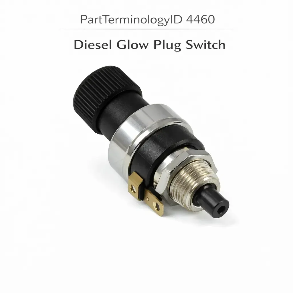
PartTerminologyID 4460, Diesel Glow Plug Switch, is the thermostatic or electronic control switch that governs the activation and duration of the diesel engine's glow plug preheat circuit, monitoring coolant temperature or intake air temperature to determine the appropriate preheat duration before the ignition key reaches the start position, illuminating the preheat indicator in the instrument cluster while the glow plugs are energized, signaling the indicator to extinguish when preheat is complete and the engine is ready to crank, and in many applications continuing to energize the glow plugs for a post-start afterglow interval that supports combustion stability during the cold-start warm-up period. That definition covers the glow plug circuit timing and control function correctly and leaves unresolved every question that determines whether the replacement switch's preheat duration calibration matches the original for the specific engine's glow plug resistance and combustion chamber design, whether the switch is compatible with the system voltage (12 volt or 24 volt), whether the switch controls the glow plug relay coil circuit or carries the full glow plug current directly, whether the switch's temperature sensing element matches the coolant passage thread specification and coolant temperature range of the original installation, whether the switch includes the post-start afterglow function or only the pre-crank preheat function, whether the switch is compatible with the instrument cluster's preheat indicator lamp circuit, and whether the switch is a standalone thermostatic timer type or an electronic module type that integrates glow plug diagnostics and individual plug fault detection.
It does not specify the preheat duration calibration, system voltage, relay or direct circuit position, temperature sensing thread specification, afterglow function, indicator lamp compatibility, or diagnostic capability. A listing under PartTerminologyID 4460 that states only year, make, and model without system voltage and preheat duration cannot be evaluated by a technician replacing a failed glow plug switch on a 24-volt commercial diesel application where the original switch was calibrated for 24-volt glow plug relay coil operation and the replacement is a 12-volt calibrated unit that applies 12 volts to a relay coil designed for 24-volt operation, producing a relay coil that never develops sufficient magnetic force to close the glow plug power contacts and leaving all glow plugs permanently de-energized regardless of ambient temperature.
For sellers, PartTerminologyID 4460 is the diesel cold-start PartTerminologyID where system voltage is the most immediately consequential attribute because a 12-volt switch in a 24-volt system or a 24-volt switch in a 12-volt system produces either a relay that never activates or a relay coil that burns out from double its rated voltage within the first preheat cycle. Both outcomes leave the diesel engine without glow plug preheat, which on a cold morning at minus 10 degrees Celsius means the engine either cranks for an extended period without starting or does not start at all, leaving the driver stranded.
What the Diesel Glow Plug Switch Does
Pre-Crank Preheat Duration and the Temperature-Based Calibration Function
The glow plug switch monitors coolant temperature (or intake air temperature on some applications) and determines the appropriate preheat duration from a calibration table embedded in the switch's thermal or electronic control circuit. At low coolant temperatures (minus 20 degrees Celsius and below), the switch provides maximum preheat duration, typically 6 to 15 seconds depending on the engine and glow plug design, to bring the combustion chamber walls and the compressed air charge to the temperature needed for reliable fuel ignition. At higher coolant temperatures (above 40 to 60 degrees Celsius, depending on the switch calibration), the switch provides minimal or zero preheat duration because the engine's thermal mass is sufficient to support cold start without glow plug assistance.
The preheat duration calibration is specific to the combination of glow plug type (pencil-type fast-glow plugs reaching operating temperature in 2 to 4 seconds versus conventional glow plugs requiring 8 to 15 seconds), combustion chamber geometry, compression ratio, and engine displacement. An engine using fast-glow pencil-type plugs requires a switch calibrated for a shorter preheat duration at each temperature point. Installing a switch calibrated for conventional glow plug preheat durations on an engine with fast-glow plugs will overheat the fast-glow elements, shortening their service life through repeated thermal stress cycling beyond their designed operating temperature.
The preheat indicator in the instrument cluster illuminates when the switch activates the glow plug relay and extinguishes when the switch determines preheat is complete and the engine can be cranked. The driver's cue to attempt starting is the extinguishing of the preheat indicator, and a switch that terminates preheat prematurely (too short a duration at low temperature) will extinguish the indicator before the glow plugs have reached operating temperature, inviting a crank attempt on inadequately preheated plugs that may or may not produce ignition.
System Voltage and the 12-Volt versus 24-Volt Distinction
Diesel glow plug systems operate at either 12 volts or 24 volts. Passenger car and light commercial diesel applications use 12-volt systems. Heavy commercial diesel applications (trucks, buses, construction equipment) frequently use 24-volt systems. The glow plug switch must be calibrated and rated for the specific system voltage for two independent reasons.
The first reason is relay coil compatibility. The glow plug relay coil is wound to produce the required magnetic force at either 12 or 24 volts. A 12-volt switch applying 12 volts to a 24-volt relay coil develops only half the required magnetic force, which is insufficient to close the relay power contacts and energize the glow plugs. The glow plugs receive no current and provide no preheat. A 24-volt switch applying 24 volts to a 12-volt relay coil applies double the rated voltage to the coil winding, producing four times the rated coil current and rapidly destroying the coil insulation through thermal overload.
The second reason is the switch's own temperature-sensing and timing circuit calibration. Electronic glow plug controllers use supply voltage as a reference for their internal timing circuits. A controller calibrated for 12-volt operation receives a different supply voltage ratio when powered at 24 volts, producing timing intervals that do not match the designed preheat durations at each temperature point.
The system voltage must be the first confirmed attribute for every glow plug switch listing, preceding all other specifications including preheat duration and temperature range.
Relay Coil Circuit versus Direct Glow Plug Current
The glow plug switch is placed in the glow plug circuit at one of two positions. In relay-controlled systems, the switch controls the relay coil circuit only and carries the relay coil current (typically 0.2 to 0.5 amperes). The relay power contacts carry the full glow plug current, which for a four-cylinder diesel with four glow plugs drawing 15 to 20 amperes each can reach 60 to 80 amperes total. The switch in this position needs only a modest contact current rating for the relay coil.
In some older and simpler glow plug systems, the switch carries the full glow plug current directly through its own contacts, with no intermediate relay. These direct-current switches require contacts rated for the full glow plug load current and are physically larger and more robust than relay coil switches. A relay coil-rated switch installed directly in a full glow plug current circuit will arc and weld its contacts under the first preheat activation event at 60 to 80 amperes, permanently closing the glow plug circuit and leaving all plugs energized continuously.
The circuit position (relay coil or direct current) must be confirmed from the vehicle's circuit diagram and stated in the listing before the current rating is evaluated.
Post-Start Afterglow Function and Cold-Start Combustion Stability
The afterglow function continues to energize the glow plugs for a fixed interval after the engine starts, typically 30 seconds to 3 minutes depending on the coolant temperature at start. During the afterglow period, the glow plugs continue to provide heat to the combustion chamber, supporting complete combustion of the fuel during the cold-start warm-up phase when combustion chamber wall temperatures are below the diesel's optimal combustion temperature. The afterglow reduces white smoke (unburned fuel) from the exhaust during the warm-up period and improves combustion stability and idle quality on cold starts.
A replacement switch without the afterglow function in an application that includes it will produce noticeably increased white smoke during cold starts and rougher idle during the first 30 to 60 seconds after cold start, as combustion stability is reduced without the afterglow heat contribution. The driver may attribute this to a fuel system issue or an injector problem rather than recognizing the absent afterglow function as the cause.
The afterglow function inclusion must be stated as a mandatory attribute for every glow plug switch listing. A switch without afterglow installed in an afterglow application does not produce a hard fault code on most pre-OBD diesel systems, which means the absence of the afterglow function may go undiagnosed for the entire service life of the replacement switch.
Electronic Glow Plug Controller versus Thermostatic Timer Switch
Glow plug control is implemented in two hardware types. The thermostatic timer switch uses a bimetallic element or a simple RC timing circuit to determine preheat duration based on the temperature of the sensing element, which heats up from the coolant passage temperature. As the sensing element warms, the bimetallic element deflects or the RC circuit charges, terminating preheat when the element reaches the calibrated temperature. The thermostatic type is self-contained, requires no external temperature sensor input, and is the simpler and less expensive of the two types.
The electronic glow plug controller is a microcontroller-based module that receives temperature input from the engine coolant temperature sensor (shared with the ECU or a dedicated sensor), calculates the optimal preheat duration from a stored calibration map, activates the glow plug relay, monitors individual glow plug current draw to detect failed plugs, and communicates diagnostic status to the instrument cluster or the ECU through a digital output. The electronic controller provides more accurate preheat duration calibration across the full temperature range and adds individual plug fault detection that is absent in thermostatic types.
A thermostatic timer switch installed in an electronic controller application will not provide individual plug fault detection, digital diagnostic output, or the more precise preheat duration calibration of the original electronic controller. The switch type (thermostatic timer or electronic controller) must be stated and confirmed before ordering.
Why This Part Generates Returns
Buyers return diesel glow plug switches because the replacement is a 12-volt calibrated unit and the application is a 24-volt commercial diesel system where the relay coil receives only 12 volts and never closes, leaving all glow plugs de-energized and the engine unable to cold start; the preheat duration is calibrated for conventional glow plugs and the engine uses fast-glow pencil plugs, causing repeated overheat stress of the plug elements within the first month of winter use; the replacement does not include the post-start afterglow function and the engine produces excessive white smoke and rough idle during every cold-start warm-up on mornings below 5 degrees Celsius; the switch carries the relay coil current rating of 0.5 amperes and the circuit routes full glow plug current of 65 amperes through the switch contacts directly, welding the contacts on the first preheat event; the temperature sensing thread is M10 x 1.0 metric and the coolant passage uses a 3/8-18 NPT port, producing a partial engagement that allows coolant to weep at the switch base and introduces air into the sensing element chamber; the replacement is a thermostatic timer type and the original was an electronic controller with individual plug fault detection, removing the diagnostic capability from the instrument cluster warning system; and the preheat indicator lamp output in the replacement is designed for a 12-volt direct lamp circuit and the vehicle has a BCM indicator input circuit rated for 5 volts, overloading the BCM indicator input on every preheat cycle.
Top Return Scenarios
Scenario 1: "12-volt switch in 24-volt system, relay coil receives half voltage, glow plugs never energized"
The buyer replaces the glow plug switch on a 24-volt commercial diesel. The listing covers the engine family without specifying system voltage. The delivered switch applies 12 volts to the 24-volt glow plug relay coil. The coil develops insufficient magnetic force to close the power contacts. All glow plugs remain de-energized regardless of ambient temperature. On a minus 15 degree Celsius morning, the engine cranks without starting. The driver is stranded.
Prevention language: "System voltage: [12 volt / 24 volt]. This switch is calibrated and rated for [voltage] operation. Verify system voltage before ordering. A 12-volt switch in a 24-volt system applies half the rated coil voltage, preventing relay closure. A 24-volt switch in a 12-volt system applies double the rated coil voltage, destroying the relay coil on the first preheat cycle."
Scenario 2: "Conventional plug duration calibration on fast-glow pencil plugs, plugs overheated within first winter"
The replacement switch is calibrated for an 8-second preheat at minus 10 degrees Celsius. The engine uses fast-glow pencil plugs that reach operating temperature in 3 seconds and are designed for a maximum continuous energization of 5 seconds per preheat cycle. The 8-second preheat duration exceeds the fast-glow plugs' thermal design limit on every cold morning below minus 5 degrees Celsius. After six weeks of winter use, two of the four plugs fail with broken heating elements.
Prevention language: "Glow plug type compatibility: [conventional glow plugs, rated for [X] second maximum preheat / fast-glow pencil plugs, rated for [X] second maximum preheat]. Verify the glow plug type installed in the engine before ordering. A switch calibrated for conventional plug preheat durations will overheat fast-glow pencil plugs on every cold preheat event."
Scenario 3: "No afterglow function, white smoke and rough idle during every cold-start warm-up"
The buyer installs the replacement switch. The engine starts normally on cold mornings. During the first 45 seconds after cold start, the exhaust produces dense white smoke and the idle is rough and occasionally stumbles. The original switch provided a 90-second afterglow interval at coolant temperatures below 20 degrees Celsius. The replacement switch terminates glow plug activation at the end of the pre-crank preheat period. Without afterglow heat support, combustion stability drops during the first warm-up phase.
Prevention language: "Afterglow function: [included, [X] second afterglow interval at coolant temperatures below [X] degrees Celsius / not included, pre-crank preheat only]. Verify whether the original switch includes an afterglow function. A switch without afterglow in an afterglow application produces white smoke and rough idle during cold-start warm-up on every sub-threshold-temperature start."
Scenario 4: "Relay coil switch contacts welded under direct glow plug current, plugs permanently energized"
The buyer installs the replacement switch with relay coil-rated contacts of 0.5 amperes. The vehicle circuit routes the full glow plug current of 65 amperes through the switch contacts without an intermediate relay. On the first preheat activation, the switch contacts arc under 65 amperes and weld in the closed position. All glow plugs remain permanently energized. The glow plugs overheat and fail within 24 hours of continuous energization.
Prevention language: "Circuit position: [relay coil control circuit, [X] ampere maximum / direct glow plug current circuit, [X] ampere maximum]. Contact current rating: [X] amperes. A relay coil-rated switch installed directly in the glow plug power circuit will weld its contacts under the full glow plug load current, permanently energizing all plugs and causing rapid glow plug failure."
Scenario 5: "Thermostatic timer in electronic controller application, individual plug fault detection absent, failed plug undetected"
The buyer installs a thermostatic timer switch in place of the original electronic glow plug controller. The engine starts and the preheat indicator functions. After three months, one glow plug element burns out. The thermostatic timer has no individual plug current monitoring capability and does not detect the open circuit in the failed plug. The instrument cluster shows no glow plug fault warning. The engine experiences progressively harder cold starts as ambient temperature drops, attributable to the single failed plug, but no warning directs the technician to the plug fault.
Prevention language: "Controller type: [thermostatic timer, preheat duration only / electronic controller with individual plug fault detection and diagnostic output]. A thermostatic timer replacement in an electronic controller application removes individual plug fault detection. Failed glow plugs will not be reported to the instrument cluster, and progressive hard cold-start symptoms may not be attributed to a plug fault without active diagnostic investigation."
Core Listing Attributes for PartTerminologyID 4460
PartTerminologyID: 4460
Component: Diesel Glow Plug Switch
System voltage: 12 volt or 24 volt (mandatory, in title)
Controller type: thermostatic timer or electronic controller with diagnostics (mandatory, in title)
Preheat duration at key temperature points: minimum and maximum ambient, in seconds (mandatory)
Afterglow function: included with duration and temperature threshold, or not included (mandatory)
Glow plug type compatibility: conventional or fast-glow pencil type (mandatory)
Circuit position: relay coil control or direct glow plug current (mandatory)
Contact current rating in amperes (mandatory)
Temperature sensing type: coolant passage with thread specification, or external sensor input (mandatory)
Thread specification for coolant sensing types: diameter, pitch, thread form (mandatory)
Indicator lamp output type: direct lamp circuit or BCM input with voltage rating (mandatory)
Connector pin count and terminal type (mandatory)
Year/make/model/engine/displacement
Catalog Checklist for ACES/PIES Teams
PartTerminologyID = 4460
Require system voltage in title: 12 volt or 24 volt (mandatory)
Require controller type in title: thermostatic timer or electronic controller (mandatory)
Require preheat duration calibration with temperature points (mandatory)
Require afterglow function: included or not included (mandatory)
Require glow plug type compatibility: conventional or fast-glow (mandatory)
Require circuit position: relay coil or direct current (mandatory)
Require contact current rating (mandatory)
Require temperature sensing thread specification for coolant sensing types (mandatory)
Require indicator lamp output voltage rating (mandatory)
Prevent system voltage omission: a 12-volt switch in a 24-volt system prevents relay closure; a 24-volt switch in a 12-volt system destroys the relay coil; system voltage is the first confirmed attribute and must be in the title without exception
Prevent glow plug type omission: conventional plug preheat durations overheat fast-glow pencil plugs on every cold start; glow plug type compatibility must be confirmed before ordering
Prevent afterglow omission: a switch without afterglow in an afterglow application produces white smoke and rough idle during warm-up on every sub-threshold cold start; afterglow function must be stated for every listing
Prevent circuit position omission: a relay coil-rated switch in a direct current circuit welds contacts under glow plug load current; circuit position must be confirmed before contact current rating is evaluated
Prevent controller type conflation: a thermostatic timer in an electronic controller application removes individual plug fault detection; controller type must be stated and confirmed
Differentiate from Glow Plug (if cataloged): the glow plug is the heating element in the combustion chamber; the glow plug switch controls the relay that energizes the plugs; a switch that activates the relay correctly but the engine still hard-starts confirms a failed glow plug rather than a failed switch; test individual plug resistance before replacing the switch on a hard cold-start complaint
Differentiate from Glow Plug Relay (if cataloged): the relay is the power switching component the switch commands; a switch that activates its output correctly but the plugs receive no current indicates a failed relay rather than a failed switch; confirm relay coil continuity and contact function before replacing the switch
FAQ (Buyer Language)
How do I know if my diesel runs a 12-volt or 24-volt system?
Check the battery configuration. A 24-volt system uses two 12-volt batteries wired in series, with a positive cable connecting the positive terminal of one battery to the negative terminal of the second and the vehicle's positive supply taken from the second battery's positive terminal. A 12-volt system uses a single 12-volt battery or two 12-volt batteries wired in parallel. Alternatively, measure the voltage across the vehicle's positive and negative supply terminals with a multimeter: approximately 12.5 to 12.8 volts confirms a 12-volt system and approximately 25 to 25.6 volts confirms a 24-volt system.
My diesel starts fine in warm weather but is hard to start in cold weather after replacing the glow plug switch. What should I check?
A diesel that starts normally above 10 degrees Celsius but requires extended cranking or multiple attempts below 5 degrees Celsius after a switch replacement points to either a preheat duration calibrated for a warmer baseline than the original (extinguishing the indicator before the plugs have reached operating temperature at low ambient) or the absence of an afterglow function that the original provided. Confirm the replacement switch's preheat duration at the coldest temperatures you experience and confirm whether the switch includes afterglow. Also verify the glow plug type matches the switch's calibration.
What does white smoke from the exhaust on cold mornings indicate about the glow plug system?
White smoke during cold-start warm-up (distinct from the brief blue-gray smoke on initial start) indicates unburned fuel in the exhaust resulting from incomplete combustion during the first warm-up phase. The most common cause after a glow plug switch replacement is the absence of an afterglow function that was providing combustion heat support during the warm-up period. Confirm whether the original switch included afterglow and whether the replacement does also.
Can I use a glow plug switch from a naturally aspirated diesel on a turbocharged diesel of the same displacement?
Not without confirming the preheat duration calibration matches. Turbocharged diesel engines have different combustion chamber temperatures and different cold-start fuel atomization characteristics than naturally aspirated engines of the same displacement. The preheat duration calibration may differ between the two variants even at the same engine displacement. Confirm the preheat duration specifications from the factory service manual for the specific engine variant before ordering.
How do I test whether the glow plug switch is activating the relay?
Connect a test lamp or a low-current meter between the relay coil terminals (not the power contacts) with the ignition in the preheat position. A functioning switch will deliver the system voltage to the relay coil terminals during the preheat interval, illuminating the test lamp. If the test lamp does not illuminate but the system voltage is present at the switch supply terminal, the switch output has failed. If the system voltage is absent at the switch supply terminal, the issue is upstream of the switch in the ignition circuit.
Related PartTerminologyIDs
Glow Plug (if cataloged): the heating element in the combustion chamber; a switch that activates correctly but cold start remains difficult confirms a failed plug or plugs; test individual plug resistance (typically 0.5 to 2 ohms for a functional plug) before replacing the switch on a hard cold-start complaint
Glow Plug Relay (if cataloged): the power switching component the switch commands; a switch that activates its relay coil output correctly but glow plugs receive no power confirms a failed relay contact rather than a failed switch; test relay contact continuity under load before replacing the switch
Engine Coolant Temperature Sensor (if shared with glow plug controller): on electronic controller applications that share the ECT sensor with the ECU, a failed ECT sensor produces incorrect preheat duration calculation in addition to fuel and ignition management errors; a hard cold-start complaint after switch replacement on an electronic controller application should include ECT sensor verification before attributing the fault to the switch
Status in New Databases
PIES/PCdb: PartTerminologyID 4460, Diesel Glow Plug Switch
PIES 8.0 / PCdb 2.0: No change in PartTerminologyID or terminology label
Final Take for PartTerminologyID 4460
Diesel Glow Plug Switch (PartTerminologyID 4460) is the diesel cold-start PartTerminologyID where system voltage is the attribute with the most immediate and severe consequence of mismatch, because a voltage mismatch either prevents relay closure entirely (12-volt switch in a 24-volt system) or destroys the relay coil on the first preheat cycle (24-volt switch in a 12-volt system), leaving the diesel engine without glow plug preheat in the coldest conditions where preheat is most critical. The glow plug type compatibility is the attribute with the most progressive consequence, because conventional plug preheat durations overheat fast-glow pencil plugs on every cold-morning start, accumulating thermal stress that produces element failure within one winter season. The afterglow function is the attribute with the most operationally invisible consequence, because its absence produces white smoke and rough idle without generating a fault code on most pre-OBD diesel systems.
State the system voltage in the title. State the controller type in the title. State the preheat duration calibration with temperature points. State the afterglow function. State the glow plug type compatibility. State the circuit position and contact current rating. State the temperature sensing thread specification. For PartTerminologyID 4460, system voltage, glow plug type compatibility, and afterglow function are the three attributes that prevent the three most consequential return scenarios in the diesel glow plug switch buyer population.