Fuel Tank Sending Unit (PartTerminologyID 4436): Float Arm Geometry, Resistance Range Calibration, and Fuel Gauge Circuit Compatibility
Written by Arthur Simitian | PartsAdvisory
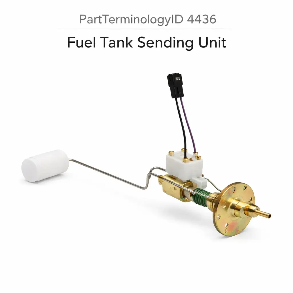
PartTerminologyID 4436, Fuel Tank Sending Unit, is the electromechanical assembly mounted in the fuel tank that monitors the fuel level by means of a float attached to a pivoting arm whose position varies the resistance output of a rheostat or resistive track circuit, sending a continuously variable resistance signal to the fuel gauge in the instrument cluster, the ECU's fuel level input, or a dedicated fuel level module that translates the resistance into a displayed fuel level reading, and in many applications the sending unit is integrated into a combined fuel pump and sending unit module mounted through a single tank access opening, combining the fuel delivery and level sensing functions in a single serviceable assembly. That definition covers the fuel level sensing and signal output function correctly and leaves unresolved every question that determines whether the replacement sending unit's resistance range matches the fuel gauge's calibration for the full range from empty to full, whether the float arm geometry and float travel arc match the internal dimensions of the specific fuel tank so the float reaches the full position at a full tank without contacting the tank walls and reaches the empty position at the minimum fuel level without lifting off the fuel surface, whether the replacement is a standalone sending unit for a tank with a separate fuel pump assembly or a combined fuel pump and sending unit module, whether the sending unit mounting flange geometry and mounting tab count match the tank's access opening, whether the fuel pump electrical connector and fuel pump flow rate (if integrated) match the original, whether the float material and arm material are compatible with the fuel type in the tank including E85 ethanol blends, and whether the sending unit includes the fuel pump strainer and any anti-slosh baffle required by the specific tank design.
It does not specify the resistance range, float arm geometry, float travel arc, mounting configuration, fuel pump integration, flange geometry, fuel compatibility, or strainer inclusion. A listing under PartTerminologyID 4436 that states only year, make, and model without resistance range and float arm geometry cannot be evaluated by a technician replacing a failed sending unit on a vehicle where the fuel gauge circuit uses a 10 to 180 ohm resistance range (10 ohms at full, 180 ohms at empty) and the replacement produces a 0 to 90 ohm range, causing the gauge to read approximately half of the actual fuel level at all points on the scale, and where the float arm is 15mm shorter than the original, causing the gauge to read full before the tank reaches actual capacity and to read empty when approximately 2 gallons of usable fuel remain in the tank rather than the original 0.5 gallon reserve.
For sellers, PartTerminologyID 4436 is the fuel system PartTerminologyID where inaccurate level reading is the most common consequence of a mismatch and the safety consequence of persistent inaccurate reading is a driver who runs out of fuel based on a gauge that consistently over-reads the actual level. A sending unit that reads one quarter tank higher than actual on every tank fills the driver with false confidence that leads to a fuel starvation event at an inconvenient or unsafe location. The resistance range and float arm geometry are not optional fitment refinements; they are the specifications that determine whether the gauge is accurate or systematically misleading.
What the Fuel Tank Sending Unit Does
Float Arm Geometry and the Tank Interior Dimension Dependency
The float arm is the pivoting lever that connects the buoyant float to the rheostat wiper contact. As the fuel level rises, the float rises and rotates the arm upward, moving the wiper contact along the resistive track. As the fuel level falls, the float descends and moves the wiper in the opposite direction. The resistance at the wiper contact changes continuously through the arm's rotation range, and this resistance is the signal the sending unit delivers to the fuel gauge circuit.
The float arm geometry (length, pivot offset, and arc of travel) must match the specific fuel tank's internal dimensions to produce accurate level readings across the full tank depth. A float arm that is too long will contact the tank wall or floor before the fuel level reaches the bottom, preventing the float from reaching its lowest position and causing the gauge to read above empty when the tank is nearly dry. A float arm that is too short will not allow the float to reach the full-tank surface at maximum capacity, causing the gauge to read below full when the tank is completely filled.
The float arm's lateral offset from the sender mounting position determines the horizontal location of the float within the tank relative to the sending unit body. A float arm with the wrong lateral offset positions the float above the fuel pump strainer intake or against the tank's internal baffles, producing float restriction that prevents smooth travel through the full arc and causing the gauge to stick at specific levels while the actual fuel level changes.
The tank shape also determines the float arm's arc of travel requirement. A shallow wide tank requires a float arm calibrated for a shallow travel arc. A tall narrow tank requires a float arm calibrated for a steep travel arc. The same float arm length produces different arc geometry in tanks of different internal proportions, and the arm geometry must be matched to the specific tank, not merely to the vehicle.
Resistance Range Calibration and Fuel Gauge Compatibility
The resistance range of the sending unit (the resistance at empty and the resistance at full) must match the calibration of the fuel gauge or fuel level module that receives the signal. Automotive fuel gauge circuits use one of two resistance conventions: the positive convention where resistance increases from full to empty (for example, 10 ohms at full and 180 ohms at empty, used on most domestic applications), and the negative convention where resistance decreases from full to empty (for example, 300 ohms at full and 10 ohms at empty, used on many European and Japanese applications and some domestic applications from specific manufacturers).
Within the positive convention, the specific resistance values at full and empty vary significantly between manufacturers and model years. General Motors applications historically used 0 to 90 ohms (0 at full, 90 at empty). Ford applications historically used 10 to 180 ohms (10 at full, 180 at empty). Chrysler applications used various ranges. Many import manufacturers used the 300 to 10 ohm negative convention. Installing a GM 0 to 90 ohm sender in a Ford 10 to 180 ohm gauge circuit will produce a gauge that reads approximately half the actual level at every point on the scale, because the gauge is calibrated to deflect full-scale with a 170-ohm signal change but the sender provides only an 90-ohm signal change.
The resistance convention (positive or negative) and the specific full and empty resistance values must both be stated in every sending unit listing. A listing that states only "compatible with Ford applications" without stating the resistance values is insufficient because different Ford gauge circuits use different resistance ranges across model years and platforms.
Standalone Sending Unit versus Integrated Fuel Pump and Sending Unit Module
The sending unit is produced in two installation configurations. The standalone sending unit is a resistive assembly with a float arm that installs through the tank access opening independently of the fuel pump. The fuel pump is either a separate module at a different access opening or is a mechanical pump external to the tank. Standalone sending units are used on many older carbureted and early fuel-injected vehicles with mechanical fuel pumps, and on some modern vehicles with a separate fuel pump access opening from the sending unit opening.
The integrated fuel pump and sending unit module combines the electric fuel pump, the fuel pump strainer, the fuel level sending unit, the pressure regulator on returnless fuel systems, and the fuel level float arm into a single assembly that installs through one tank access opening. The integrated module is the dominant configuration on fuel-injected vehicles from the 1990s onward. A replacement for an integrated module must match the fuel pump's rated flow rate and pressure output in addition to the sending unit's resistance range and float arm geometry.
A buyer who orders a standalone sending unit for an integrated module application will receive a component that cannot be installed in the tank's single access opening and that does not include the fuel pump function needed to deliver fuel to the engine. A buyer who orders an integrated module for a standalone sending unit application will receive a component that requires a larger access opening than the tank provides and that includes a fuel pump that will be left unconnected. The configuration (standalone or integrated module) must be stated in the listing title and confirmed before any other specification.
Mounting Flange Geometry, Tab Count, and Lock Ring Specification
The sending unit or integrated module mounts in the tank through a circular access opening sealed by a flange and lock ring assembly. The flange diameter, the number of mounting tabs around the flange perimeter, and the lock ring thread specification must match the tank's access opening for the unit to seat and seal correctly.
The flange diameter is determined by the tank access opening diameter, which is specific to the tank design. A flange that is too large will not fit through the opening. A flange that is too small will seat in the opening but the lock ring will not engage the tank's retaining thread or the mounting tabs will not align with the tank's tab slots, allowing the assembly to rotate under operating pressure or vibration.
The mounting tab count and tab spacing determine the rotational positions at which the sending unit can be locked in the tank. A sending unit with six tabs at 60-degree intervals will only lock at positions that align all six tabs with the tank's six slot positions. Rotating the assembly to the position that aligns the fuel pump outlet with the fuel supply line requires all tabs to align simultaneously, which is possible only if the tab count and spacing match the tank exactly.
The lock ring thread specification (diameter and thread pitch) must match the tank's retaining thread. An incorrect thread specification will either prevent lock ring engagement (if the diameter is wrong) or allow partial engagement without developing the compressive force needed to seal the flange gasket against the tank (if the pitch is wrong).
Fuel Pump Flow Rate and Pressure Specification for Integrated Modules
When the sending unit is part of an integrated fuel pump module, the fuel pump's rated flow rate and maximum output pressure must match the original module's specifications. A replacement module with a lower flow rate than the original will not supply adequate fuel at high engine load conditions, producing a lean condition, power loss, and potential engine damage at maximum demand. A replacement module with a higher flow rate than the original is generally acceptable from a safety standpoint but may produce higher fuel system operating pressure that stresses the pressure regulator and fuel rail connections if the pressure regulator is not included in the replacement module.
The fuel pump strainer included in the integrated module must match the fuel pump's inlet specification. A strainer with too fine a mesh will restrict flow to the pump during cold starts when fuel viscosity is higher, producing a lean condition on cold start and increasing pump cavitation wear. A strainer with too coarse a mesh will allow particulates above the injector filter's capacity to reach the high-pressure pump, potentially damaging injector tips or the high-pressure pump's inlet check valves.
Float and Arm Material Compatibility with Fuel Types
The float body is typically a sealed foam or hollow metal sphere that must remain buoyant in the specific fuel type throughout the service life of the sending unit. Nitrophyl foam floats used on many domestic applications are compatible with gasoline and low-ethanol blends but absorb ethanol from E85 fuel, gaining weight over time and eventually sinking to a partially submerged position that causes the gauge to read below the actual fuel level. The rate of ethanol absorption depends on the ethanol concentration: E10 blend absorption is negligible over a normal service interval, but E85 exposure accelerates absorption substantially.
On flex-fuel vehicles certified for E85 operation, the float material must be fluoroelastomer-coated or stainless steel to resist ethanol absorption and maintain accurate buoyancy throughout the service life. A nitrophyl float installed in an E85 flex-fuel tank will begin reading low within the first year of E85 use, and the inaccuracy will worsen progressively as the float absorbs more ethanol. The driver may compensate by refueling at a higher indicated level, but the float's progressive absorption means the compensation amount increases over time.
The arm material must also be compatible with the fuel in the tank. Steel arms develop rust in high-ethanol fuels if not coated with a corrosion-resistant finish. Plastic arms used in many modern applications are generally fuel-compatible but the specific plastic formulation must be confirmed for high-ethanol content exposure. A listing that states only "fuel compatible" without identifying the float material and the specific fuel compatibility is insufficient for flex-fuel applications.
Multi-Tank Systems, Auxiliary Tank Sending Units, and Saddle Tank Configuration
Saddle tank geometry and the split-tank float arm requirement
Many pickup trucks and SUVs use saddle-shaped fuel tanks that wrap around the driveshaft tunnel, creating a tank with two separate chambers connected by a crossover passage at the bottom. In a saddle tank, the fuel level in both chambers must be represented by a single gauge reading. The sending unit in a saddle tank application is often supplemented by a transfer pump or a fuel level equalizer that maintains equal fuel levels in both chambers, so the single sending unit in one chamber represents the overall fuel level accurately.
A replacement sending unit for a saddle tank must match the specific float arm geometry calibrated for the saddle tank chamber where the unit installs. The chamber depth, width, and the crossover passage height determine the effective arm arc and the level-to-resistance mapping. A sending unit specified for a non-saddle tank application will have a float arm calibrated for a full-depth tank rather than a half-depth saddle chamber, and the gauge reading will be inaccurate across the full scale.
Dual-tank systems and tank selector valve integration
Some pickup trucks and commercial vehicles use dual independent fuel tanks with a selector valve that directs fuel from the active tank to the fuel pump and switches the gauge to display the active tank's level. Each tank in a dual-tank system has its own sending unit, and the replacement must match the resistance range of the gauge circuit for the specific tank position (front tank or rear tank). In some dual-tank systems, the front and rear tank sending units use different resistance ranges because the tank sizes differ, and the gauge calibration for each tank accounts for the different full and empty capacity levels.
A replacement sending unit for a dual-tank application must specify which tank position it covers. A unit specified for the rear tank installed in the front tank position will produce inaccurate gauge readings calibrated for the rear tank's capacity rather than the larger or smaller front tank's capacity.
Why This Part Generates Returns
Buyers return fuel tank sending units because the resistance range is 0 to 90 ohms and the gauge circuit requires 10 to 180 ohms, causing the gauge to read at approximately half the actual fuel level on every tank; the float arm is 20mm longer than the original and contacts the tank wall 40 percent into the full travel arc, causing the gauge to read full when the tank is at 60 percent capacity and to stop rising beyond that reading even as the tank continues to fill; the unit is a standalone sending unit and the application requires an integrated fuel pump and sending unit module, providing no fuel delivery capability after installation; the mounting flange diameter is correct but the tab count is six and the tank's access opening has five tab slots, preventing the lock ring from engaging in the correct sealed position; the float material is nitrophyl foam and the vehicle is a flex-fuel application where E85 exposure causes the float to absorb ethanol and read progressively lower over the first year; the fuel pump flow rate in the integrated module is rated for a normally aspirated engine and the vehicle has a supercharged application that requires the higher-flow pump from the performance trim, producing fuel starvation at maximum boost; the float arm geometry is correct for the sedan variant of the platform and the vehicle is the extended wheelbase version where the tank is 30mm deeper, causing the gauge to read below actual at all fill levels above 75 percent; and the replacement module uses a 7-tab mounting flange and the tank's locking ring has 8 positions, allowing the module to seat but not lock with all tabs engaged simultaneously, producing a fuel leak at the flange seal on the first thermal cycle.
Top Return Scenarios
Scenario 1: "Resistance range 0 to 90 ohms in 10 to 180 ohm gauge circuit, gauge reads half of actual fuel level"
The buyer replaces the sending unit on a Ford application. The listing covers the vehicle by year and model without specifying resistance range. The delivered unit produces 0 to 90 ohms. The Ford gauge circuit is calibrated for 10 to 180 ohms at full deflection. The gauge reads full at approximately 45 percent actual fuel level and reads empty at approximately 50 percent actual fuel level below the indicated range. The driver runs the tank to empty based on the gauge before the actual fuel level is critically low.
Prevention language: "Resistance range: [X] ohms at full, [X] ohms at empty, [positive convention, resistance increases from full to empty / negative convention, resistance decreases from full to empty]. Verify the resistance range against the gauge circuit calibration. A 0 to 90 ohm sender in a 10 to 180 ohm gauge circuit reads approximately half the actual fuel level at every point on the scale."
Scenario 2: "Float arm 20mm too long, contacts tank wall at 60 percent fill, gauge cannot reach full reading"
The replacement float arm is 20mm longer than the original. At approximately 60 percent tank capacity, the float contacts the inner tank wall and cannot rise further. The gauge reads at the 60-percent-capacity resistance corresponding to the arm's wall-contact position and remains at that reading as the tank fills to 100 percent. The driver cannot confirm a full tank from the gauge.
Prevention language: "Float arm length: [X] mm. Float travel arc: [X] degrees from empty to full position. Verify the float arm geometry against the tank's internal dimensions. An arm longer than the original will contact the tank wall before reaching the full-tank position, preventing the gauge from reading above the contact-point level regardless of actual fill level."
Scenario 3: "Standalone unit ordered for integrated module application, no fuel delivery after installation"
The buyer replaces what they believe is a standalone sending unit on a vehicle with a combined fuel pump and sending unit module. The delivered standalone unit provides only the level sensing function. After installation, the fuel gauge operates correctly but the fuel pump does not receive power and the engine does not start because no fuel is being delivered from the tank to the engine.
Prevention language: "Configuration: [standalone sending unit, level sensing only / integrated fuel pump and sending unit module, includes fuel pump, strainer, and level sender]. This unit is the [configuration] type. A standalone sending unit installed in an integrated module application provides no fuel delivery. Verify the configuration against the original assembly before ordering."
Scenario 4: "Nitrophyl float in E85 flex-fuel application, float absorbs ethanol, gauge reads progressively low over first year"
The buyer installs the replacement sending unit with a nitrophyl foam float on a flex-fuel vehicle operated primarily on E85. Over the first six months, the gauge begins reading consistently 10 to 15 percent below the actual tank level confirmed by fill records. Over the following six months, the discrepancy increases to 20 to 25 percent as the float continues absorbing ethanol and its buoyancy decreases. The driver begins running the tank to actual empty based on the gauge reading, causing a fuel starvation event on the highway.
Prevention language: "Float material: [nitrophyl foam, compatible with gasoline and E10 / fluoroelastomer coated or stainless steel, required for E85 flex-fuel applications]. Nitrophyl foam floats absorb ethanol from E85 fuel over time, progressively reducing buoyancy and causing the gauge to read below the actual fuel level. The inaccuracy worsens over the float's service life and cannot be corrected without replacing the sending unit."
Scenario 5: "Fuel pump flow rate insufficient for supercharged application, fuel starvation at full boost"
The buyer replaces the integrated module on a turbocharged application with a module specified for the base naturally aspirated engine on the same platform. The base module's fuel pump is rated for 70 liters per hour at 45 psi, which is adequate for the naturally aspirated engine's maximum demand but below the turbocharged engine's maximum demand of 120 liters per hour at 55 psi. Under full boost at highway speed, the pump cannot sustain adequate fuel pressure, and the engine enters fuel cut protection to prevent detonation.
Prevention language: "Fuel pump flow rate: [X] liters per hour at [X] psi. Engine application: [naturally aspirated / turbocharged / supercharged]. Verify the fuel pump flow rate against the engine's maximum fuel demand. A pump specified for the naturally aspirated engine variant will not supply adequate fuel at the maximum demand of a forced induction engine on the same platform."
Scenario 6: "6-tab flange in 5-slot tank, lock ring cannot engage in sealed position, fuel leak at flange"
The buyer installs the replacement module with a 6-tab mounting flange. The tank's access opening has five tab slots spaced at 72-degree intervals. The 6-tab flange cannot simultaneously engage all of the tank's tab slots in any rotational position. The module appears to seat but the lock ring engages unevenly, compressing the flange gasket only over the tab positions that happen to align. The uncompressed gasket sections allow fuel vapor and liquid fuel to seep past the flange seal on the first thermal cycle.
Prevention language: "Flange tab count: [X] tabs. Tank access opening tab slot count: [X] slots. Verify the flange tab count against the tank's access opening tab slot count. A flange with a different tab count than the tank's slot count cannot engage all tabs simultaneously, preventing a fuel-tight seal at the flange gasket."
Scenario 7: "Extended wheelbase tank 30mm deeper than standard, sedan arm geometry produces low reading above 75 percent fill"
The buyer's vehicle is the extended wheelbase version of a pickup platform where the fuel tank is 30mm deeper to accommodate the longer wheelbase. The replacement sending unit is specified for the standard wheelbase version of the same model year. The standard arm geometry produces accurate readings from empty to approximately 75 percent fill. Above 75 percent, the standard float arm's arc does not reach the upper portion of the deeper tank and the gauge reads below actual from 75 percent to completely full.
Prevention language: "Tank depth: [X] mm. Float arm geometry: specified for [standard / extended] wheelbase tank configuration. Verify the tank depth and wheelbase variant before ordering. Extended wheelbase and standard wheelbase variants of the same platform may use different tank depths that require different float arm geometries for accurate full-range level reading."
Scenario 8: "Resistance convention reversed, gauge reads full when tank is empty and empty when tank is full"
The buyer replaces the sending unit on a European-specification vehicle that uses a 300 to 10 ohm negative convention (300 ohms at full, 10 ohms at empty). The replacement produces a 10 to 180 ohm positive convention (10 ohms at full, 180 ohms at empty). With a full tank, the replacement sends 10 ohms. The gauge circuit, calibrated for the 300-ohm full signal, receives 10 ohms and deflects the needle to the empty position. With an empty tank, the replacement sends 180 ohms. The gauge deflects to approximately 60 percent on a gauge calibrated for a 300-ohm full signal.
Prevention language: "Resistance convention: [positive, resistance increases from full to empty / negative, resistance decreases from full to empty]. Full resistance: [X] ohms. Empty resistance: [X] ohms. Verify the resistance convention against the vehicle's gauge circuit. A reversed resistance convention causes the gauge to read in the opposite direction from the actual fuel level."
Core Listing Attributes for PartTerminologyID 4436
PartTerminologyID: 4436
Component: Fuel Tank Sending Unit
Configuration: standalone sending unit or integrated fuel pump and sending unit module (mandatory, in title)
Resistance range: resistance at full and at empty in ohms (mandatory, in title)
Resistance convention: positive (increases from full to empty) or negative (decreases from full to empty) (mandatory)
Float arm length in mm (mandatory)
Float travel arc in degrees (mandatory)
Float material: nitrophyl foam, fluoroelastomer coated, or stainless steel (mandatory)
Arm material: steel, stainless, or plastic with compatibility note (mandatory)
Fuel type compatibility: gasoline, diesel, E85, or combination (mandatory)
Mounting flange diameter in mm (mandatory)
Mounting flange tab count and tab spacing (mandatory)
Lock ring thread specification (mandatory)
Fuel pump flow rate in liters per hour at rated pressure for integrated modules (mandatory)
Fuel pump output pressure in psi for integrated modules (mandatory)
Strainer mesh specification for integrated modules (recommended)
Anti-slosh baffle inclusion note (mandatory where applicable)
Tank variant: standard wheelbase, extended wheelbase, saddle tank, dual-tank front, or dual-tank rear (mandatory where variants differ)
Year/make/model/submodel/trim/engine/tank option
Note for production date range where resistance range or float arm geometry changed
Note for flex-fuel applications requiring fluoroelastomer float material
Note for forced induction applications requiring higher flow fuel pump in integrated module
Catalog Checklist for ACES/PIES Teams
PartTerminologyID = 4436
Require configuration in title: standalone or integrated module (mandatory)
Require resistance range with full and empty values (mandatory)
Require resistance convention: positive or negative (mandatory)
Require float arm length and travel arc (mandatory)
Require float material with E85 compatibility note (mandatory)
Require fuel type compatibility (mandatory)
Require mounting flange diameter and tab count (mandatory)
Require lock ring thread specification (mandatory)
Require fuel pump flow rate and pressure for integrated modules (mandatory)
Prevent resistance range omission: a 0 to 90 ohm sender in a 10 to 180 ohm circuit reads approximately half the actual level; resistance range is the primary accuracy specification and must be in the title without exception
Prevent resistance convention omission: a reversed convention causes the gauge to read in the opposite direction from actual level; convention must be confirmed for all import and European applications
Prevent float arm geometry omission: an arm too long contacts the tank wall before full travel; arm length and travel arc must be stated and verified against the tank's internal dimensions
Prevent float material omission: nitrophyl foam in E85 applications absorbs ethanol and reads progressively low; float material and E85 compatibility must be stated for every listing
Prevent configuration omission: a standalone sender in an integrated module application provides no fuel delivery; configuration must be in the title for every listing
Prevent tab count omission: a flange with the wrong tab count cannot seal the access opening; tab count must be verified against the tank's slot count
Prevent fuel pump flow rate omission for forced induction: a base-engine flow rate pump in a turbocharged application produces fuel starvation at full boost; pump flow rate and engine application must both be confirmed for integrated modules
Prevent tank variant conflation: extended wheelbase and saddle tank variants use different float arm geometries than standard variants; tank variant must be confirmed as a mandatory attribute on all platforms with multiple tank configurations
Differentiate from Fuel Level Sensor (if cataloged separately): on some modern vehicles the fuel level sensor is a continuous analog sensor integrated into the tank rather than a float-and-rheostat sending unit; the sensor output type (resistance, voltage, or frequency) differs from the traditional sending unit output; confirm the output type before ordering
Differentiate from Fuel Pump (PartTerminologyID 4440 or similar): the fuel pump is the standalone pump assembly on vehicles with separate pump and sending unit access openings; the sending unit is the level sensing assembly; on integrated module applications, PartTerminologyID 4436 covers the complete assembly including both functions
FAQ (Buyer Language)
How do I determine the correct resistance range for my vehicle?
The resistance range is listed in the factory service manual under the fuel gauge circuit specifications. It is also available from the original sending unit's manufacturer specification. As a reference point, most domestic GM applications use 0 to 90 ohms, most domestic Ford applications use 10 to 180 ohms, and many European applications use 300 to 10 ohms. However, exceptions exist within each manufacturer's product line across model years, and the resistance range should be confirmed from the specific vehicle's service data rather than from a general manufacturer reference.
Why does my fuel gauge read incorrectly after I replaced the sending unit?
A gauge that reads at a consistent fraction of the actual level (for example, always reads half the actual level) indicates a resistance range mismatch between the sending unit and the gauge circuit calibration. A gauge that reads consistently above or below actual by a fixed amount (for example, always reads one-quarter tank higher than actual) indicates a float arm geometry mismatch where the float arm is too short or too long for the tank's internal dimensions. A gauge that reads correctly at one point on the scale (full or empty) but diverges from actual at other points indicates a non-linear resistance track that does not match the gauge's sweep characteristic.
Does the float arm length matter if the sending unit is physically the same size as the original?
Yes. The sending unit body dimensions may be identical between correct and incorrect replacements because the body is the same across multiple float arm length variants. The float arm length is calibrated for the specific tank depth, and a shorter or longer arm produces inaccurate readings regardless of whether the body fits the mounting opening correctly. Always verify the float arm length against the original specification separately from the body fitment check.
My fuel gauge started reading low after switching to E85. Is the sending unit the cause?
A gauge that begins reading progressively lower after switching to E85 use is consistent with a nitrophyl foam float absorbing ethanol and losing buoyancy. The absorption is gradual and the inaccuracy increases over months of E85 exposure. Remove the sending unit and inspect the float: if the float has increased in weight or is partially submerged in a test container of E85, the float has absorbed ethanol and the sending unit requires replacement with a fluoroelastomer or stainless steel float version.
Can I replace just the float and arm without replacing the entire sending unit?
On some applications the float and arm are separately serviceable and can be replaced without replacing the entire sending unit body and rheostat. Confirm whether the float arm assembly is available as a separate component for the specific sending unit. On most modern integrated modules, the float arm is not separately serviceable and the complete module must be replaced if the arm geometry is incorrect or the float material is incompatible with the fuel type.
Related PartTerminologyIDs
Fuel Pump (PartTerminologyID 4440 or similar): the standalone pump assembly on vehicles with separate tank access openings for the pump and the sending unit; on integrated module applications, the pump and sending unit are combined and PartTerminologyID 4436 covers the complete assembly; confirm whether the application uses a combined or separate pump and sending unit before ordering either component
Fuel Level Sensor (if cataloged separately): on some modern vehicles a solid-state fuel level sensor replaces the traditional float-and-rheostat sending unit; the sensor output type differs from the sending unit output; confirm whether the application uses a sensor or a sending unit before ordering
Fuel Gauge (if cataloged): the instrument cluster gauge that receives the sending unit signal; a gauge that reads incorrectly after sending unit replacement confirms a resistance range mismatch if the new sending unit is functional; confirm the gauge's resistance calibration before replacing the sending unit a second time
Status in New Databases
PIES/PCdb: PartTerminologyID 4436, Fuel Tank Sending Unit
PIES 8.0 / PCdb 2.0: No change in PartTerminologyID or terminology label
Final Take for PartTerminologyID 4436
Fuel Tank Sending Unit (PartTerminologyID 4436) is the fuel system PartTerminologyID where resistance range accuracy is the attribute with the most systematic consequence of mismatch, because a sending unit reading half the actual fuel level on every tank will eventually produce a fuel starvation event when a driver trusts a gauge that consistently overstates the available fuel. The float arm geometry is the attribute with the most tank-specific consequence, because an arm 20mm longer than the original contacts the tank wall and produces an inaccurate reading every time the tank is above 60 percent full. The float material is the attribute with the most progressive consequence on flex-fuel applications, because nitrophyl foam absorbs ethanol slowly and the inaccuracy worsens every month the vehicle operates on E85.
State the configuration in the title. State the resistance range with full and empty values. State the resistance convention. State the float arm length and travel arc. State the float material and fuel type compatibility. State the mounting flange diameter and tab count. State the lock ring thread specification. State the fuel pump flow rate and pressure for integrated modules. State the tank variant where multiple configurations exist. For PartTerminologyID 4436, resistance range, float arm geometry, and float material are the three attributes that prevent the three most consequential and least immediately visible return scenarios in the fuel tank sending unit buyer population.