Fuel Injector Vacuum Switch (PartTerminologyID 4430): Vacuum Threshold Calibration, Contact Configuration, and Fuel System Circuit Compatibility
Written by Arthur Simitian | PartsAdvisory
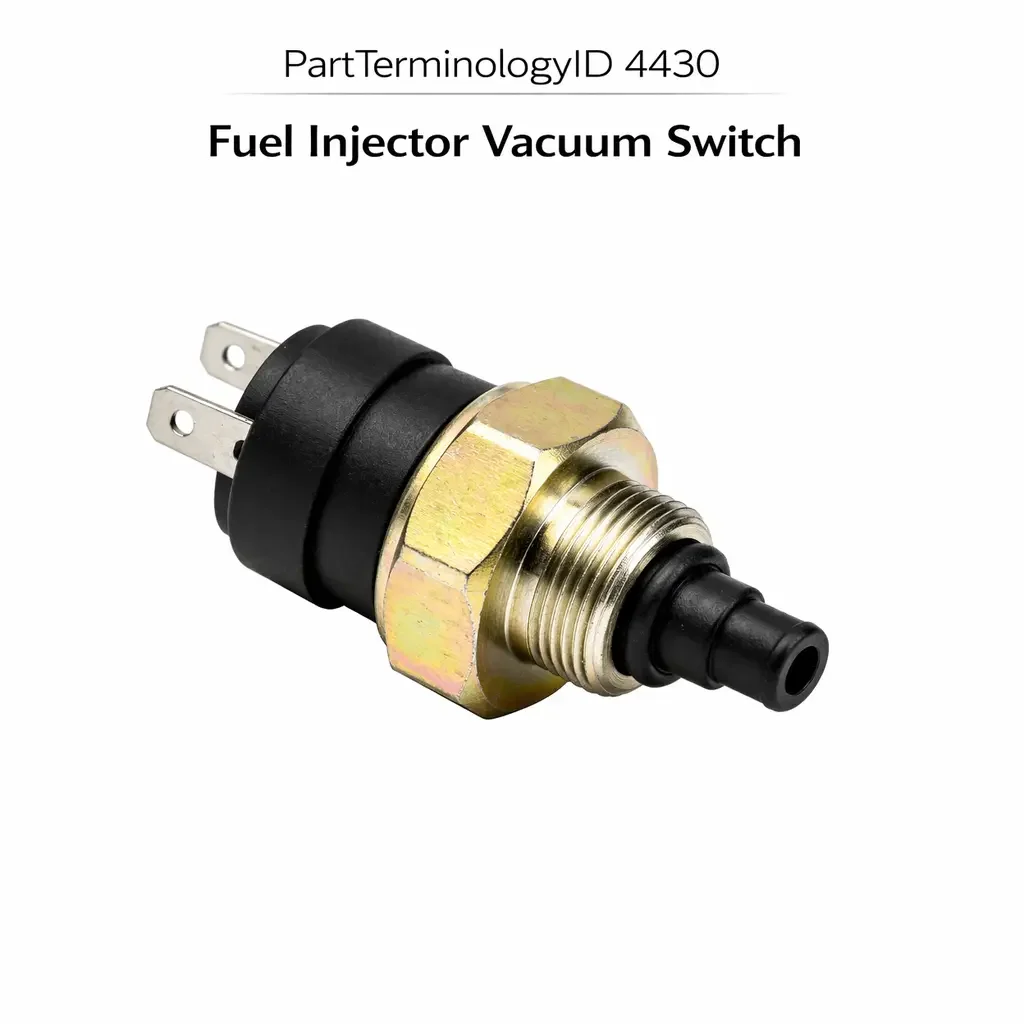
PartTerminologyID 4430, Fuel Injector Vacuum Switch, is the vacuum-sensing switch mounted in the intake manifold vacuum circuit that monitors manifold vacuum level and opens or closes an electrical contact at a calibrated vacuum threshold to control a fuel system function, most commonly used to signal the ECU or a fuel control module when the engine transitions between idle, part-throttle, and wide-open-throttle vacuum conditions so that the fuel injection strategy can be adjusted for the specific load condition, or to activate or deactivate a secondary fuel injector circuit or a fuel enrichment solenoid in response to manifold vacuum changes that indicate a shift in engine load demand. That definition covers the vacuum-sensing and fuel circuit control function correctly and leaves unresolved every question that determines whether the replacement switch's vacuum activation threshold matches the original calibration for the specific engine's vacuum range at the relevant load transition point, whether the switch is a normally open type that closes when vacuum drops below the threshold (indicating higher load) or a normally closed type that opens when vacuum drops below the threshold, whether the switch is rated for the fuel system voltage and current in the circuit it controls, whether the vacuum port size and fitting type match the manifold vacuum tap where the switch installs, and whether the switch is compatible with the ECU's input signal type on vehicles where the module expects a specific voltage level rather than a simple contact closure.
It does not specify the vacuum threshold, contact configuration, current rating, vacuum port specification, or ECU signal compatibility. A listing under PartTerminologyID 4430 that states only year, make, and model without vacuum threshold and contact configuration cannot be evaluated by a technician replacing a failed fuel injector vacuum switch on a vehicle where the original switch closed its contact when manifold vacuum dropped below 8 inches Hg, signaling the ECU to activate a secondary injector bank for high-load enrichment, and the replacement is calibrated to close below 12 inches Hg, activating the secondary injectors during part-throttle cruise where the ECU has not commanded enrichment, producing over-fueling, elevated fuel consumption, and rich exhaust at steady cruise conditions.
For sellers, PartTerminologyID 4430 is a specialized vacuum-sensing switch used primarily on carbureted and early port fuel injected engines from the 1970s through the 1990s, and on some performance injection systems where manifold vacuum is used as a load indicator for injection strategy switching. The buyer population is narrow but technically precise: a wrong threshold does not produce a no-start or a warning lamp but produces a systematic fueling error that manifests as elevated fuel consumption, rich exhaust, or hesitation at specific throttle positions, which is difficult to diagnose without identifying the switch as the cause.
What the Fuel Injector Vacuum Switch Does
Manifold Vacuum as a Load Signal and the Threshold Calibration Requirement
Manifold vacuum is a reliable indicator of engine load on naturally aspirated engines: high vacuum (15 to 22 inches Hg on a healthy engine at idle) indicates low load, and low vacuum (0 to 5 inches Hg) indicates high load or wide-open throttle. The transition between low-load and high-load vacuum levels is the signal the fuel injector vacuum switch uses to change the fuel injection strategy from a light-load efficient calibration to a high-load enriched calibration.
The vacuum threshold at which the switch changes state must correspond to the specific load transition point where the fuel strategy change is appropriate for the engine's calibration. A threshold set too high (for example, 12 inches Hg where 8 inches Hg is the designed transition) activates the high-load enrichment circuit during part-throttle cruise at vacuum levels where the engine does not require enrichment. This produces over-fueling that reduces fuel economy and increases exhaust emissions at steady-state cruise conditions. A threshold set too low (for example, 4 inches Hg where 8 inches Hg is correct) delays the enrichment activation until the engine is already at near-full load, producing a lean stumble or hesitation during the transition period between the correct threshold and the incorrectly low threshold.
Contact Configuration and the Load-Increase Trigger Logic
The contact configuration of the fuel injector vacuum switch determines whether the fuel enrichment circuit is activated by a contact closure or a contact opening when the vacuum drops to the threshold. A normally open switch closes its contact when vacuum drops below the threshold, completing the enrichment circuit and activating the secondary injectors or enrichment solenoid. A normally closed switch opens its contact when vacuum drops below the threshold, interrupting a holding circuit that keeps the enrichment circuit inactive during light-load operation.
Installing a normally open switch in a normally closed circuit position, or vice versa, produces enrichment circuit behavior that is the exact opposite of the original: the enrichment activates during light-load cruise (when the normally closed contact opens on low vacuum, interpreted by the circuit as an active enrichment command) and deactivates during high-load operation (when the normally open contact closes, which the normally closed circuit interprets as the deactivation state). This inversion produces the fueling errors described above but in the opposite direction: over-fueling at cruise and under-fueling at high load.
Vacuum Port Specification and Installation Position
The vacuum port fitting on the intake manifold or the vacuum tap where the switch installs uses a specific nipple diameter and connection type. Most applications use a 3/16-inch or 1/4-inch barbed nipple with a push-on vacuum hose connection. Some applications use a threaded port with a corresponding threaded fitting on the switch body. The vacuum port specification must match the manifold tap fitting to ensure a leak-free vacuum signal connection. A vacuum leak at the switch connection point admits atmospheric air into the manifold vacuum signal, reducing the effective vacuum level at the switch and causing the switch to read a lower vacuum than the manifold is producing, potentially shifting the effective switching threshold from the calibrated value.
Top Return Scenarios
Scenario 1: "Threshold 4 inches Hg too high, secondary injectors activate during part-throttle cruise, over-fueling at steady speed"
The replacement switch closes below 12 inches Hg. The original closed below 8 inches Hg. At steady 60 mph cruise, manifold vacuum is typically 14 to 16 inches Hg, which is above both thresholds and the secondary injectors are correctly inactive. During light acceleration from cruise (manifold vacuum dropping to 10 to 11 inches Hg), the replacement switch closes at 12 inches Hg and activates the secondary injectors. The main injection calibration already provides adequate fueling at 10 to 11 inches Hg. The secondary injectors add excess fuel, producing a momentary rich surge and elevated fuel consumption during the acceleration phase.
Prevention language: "Vacuum activation threshold: [X] inches Hg. The switch changes state when manifold vacuum drops below this value. A threshold set above the original activates the enrichment circuit during load conditions where enrichment is not needed, producing over-fueling and rich exhaust at part-throttle. Verify the threshold against the original switch specification."
Scenario 2: "Normally open switch in normally closed circuit, enrichment active at cruise, deactivated at full load"
The replacement is normally open. The circuit requires normally closed. At cruise, the normally open contact is open, but the normally closed circuit interprets an open contact as an enrichment activation signal. Secondary injectors run continuously during cruise. At high load where the vacuum drops below the threshold, the normally open contact closes. The circuit interprets the closed contact as the enrichment deactivation state and disables the secondary injectors precisely when high-load enrichment is needed.
Prevention language: "Contact configuration: [normally open, closes on vacuum drop below threshold / normally closed, opens on vacuum drop below threshold]. A normally open switch in a normally closed circuit activates enrichment at cruise and deactivates it at high load, which is the exact opposite of the intended fueling strategy."
Scenario 3: "Vacuum port size mismatch, push-on hose leaks at connection point, effective threshold shifts lower than calibrated"
The replacement switch uses a 1/4-inch barbed vacuum nipple. The manifold tap uses a 3/16-inch push-on fitting. The vacuum hose from the manifold tap does not seat securely on the larger 1/4-inch nipple and admits atmospheric air into the vacuum signal path. The effective vacuum at the switch is consistently 2 to 3 inches Hg lower than the actual manifold vacuum, causing the switch to reach its threshold 2 to 3 inches Hg earlier than calibrated.
Prevention language: "Vacuum port fitting: [3/16-inch barbed nipple / 1/4-inch barbed nipple / threaded port, specify thread]. Verify the vacuum port fitting size against the manifold tap. A fitting mismatch produces a vacuum leak at the switch connection point that shifts the effective switching threshold from the calibrated value."
Core Listing Attributes for PartTerminologyID 4430
PartTerminologyID: 4430
Component: Fuel Injector Vacuum Switch
Vacuum activation threshold in inches Hg and kPa (mandatory, in title)
Contact configuration: normally open or normally closed (mandatory)
Contact current rating in amperes (mandatory)
Vacuum port fitting type and size (mandatory)
Connector pin count and terminal type (mandatory)
ECU signal type for module-input applications (mandatory where applicable)
Year/make/model/engine/injection system
FAQ (Buyer Language)
How do I confirm the correct vacuum threshold for my application?
The vacuum threshold is listed in the factory service manual under the fuel injection system specifications for the specific engine. It is also commonly listed on the underhood tune-up label alongside the EGR and vacuum advance specifications on pre-OBD vehicles. The original switch part number cross-reference provides the most reliable confirmation.
Can I test the original switch before replacing it?
Yes. Apply a vacuum pump to the switch's vacuum port while monitoring the circuit with a continuity tester. The switch should change state at the rated threshold. A switch that changes state at a significantly different vacuum level than rated has drifted from its calibration and requires replacement.
Related PartTerminologyIDs
Engine Coolant Temperature Vacuum Control Switch (PartTerminologyID 4308): uses coolant temperature rather than manifold vacuum as the switching signal; both are vacuum circuit control switches but the triggering parameter differs; confirm which parameter (temperature or vacuum) gates the specific circuit before ordering either component
Fuel Injection Pressure Switch (PartTerminologyID 4420): monitors fuel system pressure rather than manifold vacuum; both are switching devices in the fuel injection system but at different monitoring positions and for different circuit functions
Status in New Databases
PIES/PCdb: PartTerminologyID 4430, Fuel Injector Vacuum Switch
PIES 8.0 / PCdb 2.0: No change in PartTerminologyID or terminology label
Final Take for PartTerminologyID 4430
Fuel Injector Vacuum Switch (PartTerminologyID 4430) is the fuel injection vacuum control PartTerminologyID where the vacuum threshold and contact configuration together determine the precise load transition point at which the fuel injection strategy changes, and a mismatch in either one produces a systematic fueling error that repeats at the same throttle position on every drive cycle. State the vacuum threshold in the title. State the contact configuration. State the vacuum port fitting type and size. For PartTerminologyID 4430, vacuum threshold, contact configuration, and vacuum port fitting size are the three attributes that prevent the three most common return scenarios in the fuel injector vacuum switch buyer population.