4WD Switch (PartTerminologyID 4412): Engagement Architecture, Transfer Case Protocol, and Range Position Configuration
Written by Arthur Simitian | PartsAdvisory
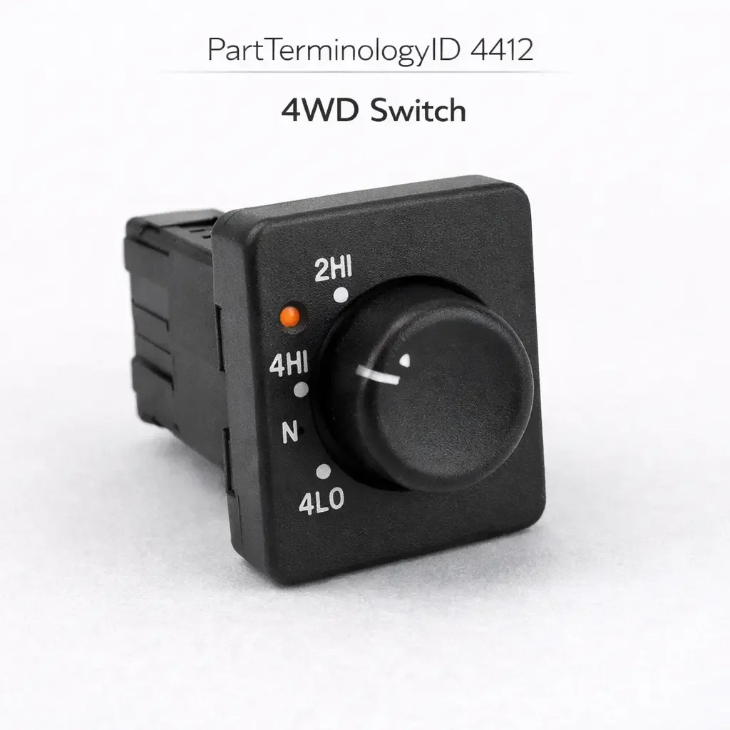
PartTerminologyID 4412, 4WD Switch, is the driver-operated control input device that commands the vehicle's four-wheel drive transfer case to shift between two-wheel drive high range, four-wheel drive high range, four-wheel drive low range, and in some systems neutral, by sending engagement commands to the transfer case control module, the transfer case shift motor, or the 4WD relay circuit depending on the vehicle's transfer case shift architecture, and in shift-on-the-fly systems commanding the front axle disconnect actuator and the transfer case synchronizer to engage the front driveshaft without requiring the vehicle to stop, while in part-time systems requiring the vehicle to be stationary for low range engagement and in full-time all-wheel drive systems governing the center differential lock or torque distribution bias rather than a discrete two-wheel to four-wheel mode transition. That definition covers the 4WD command input function correctly and leaves unresolved every question that determines whether the replacement switch matches the transfer case's specific shift architecture (electronic, mechanical push-button, rotary, or stalk-mounted), whether the switch connector pin count and terminal assignment match the harness at the center console, instrument panel, or steering column position, whether the switch is compatible with the transfer case control module's input signal type on vehicles where the module expects resistance-encoded position commands or serial bus digital commands rather than discrete contact closures for each range position, whether the switch includes position indicator outputs that illuminate 4H and 4L indicator lamps in the instrument cluster independently of the transfer case module's own indicator outputs, whether the switch is rated for the shift motor relay coil current or only the control module signal current depending on the circuit architecture, whether the replacement requires programming or module initialization after installation, and whether the replacement covers the specific combination of range positions available on the vehicle's transfer case including 2H, 4H, 4L, and neutral positions in the correct mechanical or electronic shift sequence.
It does not specify the shift architecture, connector pin count, signal type, indicator output configuration, current rating, programming requirement, or range position coverage. A listing under PartTerminologyID 4412 that states only year, make, and model without shift architecture and range position coverage cannot be evaluated by a technician replacing a failed 4WD switch on a vehicle where the original switch provided four discrete range positions (2H, 4H, 4L, and neutral) encoded as four resistance values on a single signal wire to the transfer case control module, and the replacement is a three-position switch covering only 2H, 4H, and 4L without a neutral position output, producing a transfer case module that cannot command the neutral position needed for flat towing the vehicle on a trailer and generating a module fault code for a missing input in the neutral position detection circuit.
For sellers, PartTerminologyID 4412 is the drivetrain control PartTerminologyID where the transfer case shift architecture is the most consequential attribute to confirm before any other specification, because electronic shift transfer cases and mechanical-cable transfer cases, shift-on-the-fly systems and part-time systems, and full-time AWD center differential lock systems all fall under the same PartTerminologyID despite requiring fundamentally different switch types that are physically and electrically incompatible. A rotary dial switch for an electronic shift transfer case cannot be adapted to a mechanical cable transfer case. A resistance-encoded signal switch for a module-controlled system cannot substitute for a direct relay contact switch for a relay-controlled system. Identifying the transfer case architecture is the first step and the switch selection follows from that identification.
What the 4WD Switch Does
Mechanical versus Electronic Transfer Case Shift Architectures
The transfer case shift architecture determines what the 4WD switch must physically and electrically accomplish to change drive modes. A mechanical transfer case with a floor-mounted shift lever uses the driver's direct mechanical input through a linkage to shift the transfer case internals between ranges. There is no electrical switch in this system beyond possibly a neutral indicator switch. This architecture is not typically served by PartTerminologyID 4412.
An electronic shift transfer case uses an electric shift motor inside the transfer case housing to move the range collar between positions. The 4WD switch in this architecture does not mechanically shift anything: it sends a command to the transfer case control module or directly to the shift motor relay, and the motor performs the shift. The 4WD switch in an electronic shift system is a pure signaling device, and its specifications are determined by the downstream control circuit rather than any mechanical requirement.
The shift-on-the-fly electronic transfer case adds a front axle engagement function: in addition to commanding the transfer case shift motor, the switch also signals the front axle disconnect actuator (on independent front suspension vehicles) or the free-wheeling hub engagement circuit (on solid front axle vehicles) to engage the front driveshaft and connect it to the front wheels before or simultaneously with the transfer case engagement. The switch connector on a shift-on-the-fly system has additional pins covering the front axle engagement circuit, and a replacement switch without these pins will command the transfer case engagement but leave the front axle disconnected, producing a vehicle that shows 4H engagement in the cluster indicator but delivers no drive torque to the front wheels.
Resistance-Encoded Position Signaling and the Module Calibration Dependency
On vehicles with a transfer case control module, the 4WD switch frequently uses resistance encoding to communicate the selected range position on a single signal wire. Each switch position presents a unique resistance value to the module's input pull-up circuit, and the module identifies the commanded range by measuring the resistance on the signal wire. A four-position switch may use values of 200 ohms (2H), 680 ohms (4H), 2200 ohms (4L), and 6800 ohms (neutral), with the module's lookup table mapping each resistance window to the corresponding range command.
A replacement switch with different resistance values at any position will cause the module to identify the wrong range command at that position or to record a fault for a resistance value outside any defined window. A technician who installs a replacement switch and finds that selecting 4H produces a 4L engagement or produces a fault code rather than a range transition has encountered a resistance network mismatch, not a failed module or a failed replacement switch. The resistance values for each position must be stated in the listing and verified against the original switch specification before ordering.
Serial Bus Digital Command Architecture and the Programming Requirement
On modern vehicles with CAN bus or LIN bus body electronics, the 4WD switch sends digital range selection commands on the vehicle network rather than analog resistance values or contact closures. The transfer case control module receives the command and executes the shift. The switch contains a microcontroller that encodes each range selection button press as a specific network message.
A replacement switch transmitting incorrect message identifiers will not be recognized by the transfer case module, producing no range transition in response to any switch input. On some applications the module will log a fault code for a missing or unexpected bus input. Post-installation programming is required on some serial bus 4WD switch applications to register the replacement switch's network address with the transfer case module. The listing must disclose the programming requirement and specify the required scan tool, following the same convention established for cruise control and HVAC system switch assemblies in this catalog series.
Range Position Coverage and the Neutral Position Function
The range positions available on a transfer case depend on the specific transfer case model. Common configurations include two-wheel drive high (2H), four-wheel drive high (4H), and four-wheel drive low (4L) as the standard three-position coverage. Some transfer cases add a neutral position that disconnects both driveshafts from the transfer case output, allowing the vehicle to be flat-towed on a trailer with all four wheels on the ground without driving the transmission or transfer case internals. The neutral position is also used for power take-off applications on some commercial and utility vehicles.
A switch that does not cover the neutral position on a vehicle whose transfer case has a neutral range removes the owner's ability to flat-tow the vehicle. On vehicles marketed as flat-tow capable, the neutral position is an explicitly documented capability that buyers rely on for recreational vehicle and trailer combinations. A replacement switch missing the neutral output while the transfer case module expects a resistance value for neutral on the signal wire will also generate a module fault code that the driver sees as a persistent 4WD system warning in the instrument cluster.
Indicator Lamp Outputs and the Cluster Display Independence
Many 4WD switch assemblies include dedicated indicator output pins that directly illuminate 4H and 4L indicator lamps in the instrument cluster in addition to or independently of the transfer case module's own indicator outputs. On these applications, the switch assembly carries both the range selection input signal (to the module) and the range confirmation output signal (from the switch's own contact position to the indicator lamps), providing a direct visual confirmation of the switch's position independent of the module's range completion acknowledgment.
A replacement switch without the indicator output pins leaves the 4H and 4L indicator lamps dark even though the transfer case engages the commanded range correctly, because the lamps are powered from the switch's output contacts rather than the module's outputs. The driver loses the visual confirmation of active 4WD engagement, which is particularly concerning in shift-on-the-fly situations where confirming front axle engagement before entering traction-limited terrain is important.
The indicator output configuration (whether indicators are driven by the switch directly, by the module, or by both in parallel) must be stated in the listing and the replacement must match the original's indicator architecture.
AWD Center Differential Lock and the Full-Time System Distinction
On full-time all-wheel drive vehicles with a center differential, the 4WD switch (or more accurately the AWD mode switch) governs center differential lock engagement and in some systems the torque distribution bias between front and rear axles. This system does not involve a discrete two-wheel to four-wheel mode transition because all four wheels are driven at all times. The switch commands the center differential from open (allowing speed differentiation between front and rear for normal road use) to locked (coupling front and rear at equal speed for traction-limited surfaces).
The center differential lock switch is architecturally different from a part-time 4WD switch: it typically uses a simple single-position momentary or latching button rather than a multi-position rotary or stalk selector. On vehicles where both the center differential lock function and a low-range shift function are present (as in some full-time AWD vehicles with a low range option), the switch assembly covers both functions and has a higher pin count than a differential-lock-only switch.
A listing covering a center differential lock application under PartTerminologyID 4412 must distinguish the application from a part-time 4WD switch application to prevent a buyer from ordering a multi-position rotary 4WD switch for a differential lock application or a differential lock button for a multi-position part-time transfer case application.
Why This Part Generates Returns
Buyers return 4WD switches because the replacement is a three-position type covering 2H, 4H, and 4L and the vehicle has a four-position transfer case with a neutral range, causing a transfer case module fault code for a missing neutral input and leaving the flat-tow capability permanently unavailable; the resistance values at the 4H position differ from the module's calibration table and the module commands 4L engagement when the driver selects 4H, engaging low range on a paved road and causing drivetrain stress until the driver recognizes the incorrect engagement; the replacement does not include front axle engagement output pins present in the original shift-on-the-fly switch, producing a 4H indicator in the cluster but no front axle engagement and no front traction; the replacement is a serial bus type requiring transfer case module programming and the listing describes it as direct plug-and-play, leaving the 4WD system non-functional after installation until a dealer programming session is completed; the indicator output pins are absent in the replacement and the 4H and 4L cluster indicator lamps no longer illuminate when 4WD is engaged, leaving the driver without visual confirmation of front axle engagement; the switch connector is the correct physical body type but the terminal positions are mirrored between the replacement and the original because the replacement was sourced from the opposite-hand drive market variant, causing all position commands to produce incorrect module inputs; the switch covers a full-time AWD center differential lock and the buyer's vehicle is a part-time transfer case requiring a multi-position range selector, producing a single-button assembly with no range selection capability; and the replacement requires 24 volts and the vehicle's transfer case control circuit operates at 12 volts, causing the switch indicator to remain dark and the control module to receive insufficient signal voltage at every switch position.
Top Return Scenarios
Scenario 1: "Three-position switch in four-position transfer case, neutral unavailable, module fault for missing neutral input"
The buyer's 4WD switch has failed with the transfer case stuck in 4H. The listing covers the vehicle by year and model without specifying range position coverage. The delivered switch covers 2H, 4H, and 4L. The transfer case module expects a resistance value for neutral on the signal wire when the switch is commanded to neutral. The three-position switch presents no resistance in the neutral window, producing a module fault code. The vehicle cannot be configured for flat towing and a 4WD system warning appears in the cluster.
Prevention language: "Range position coverage: [2H, 4H, 4L / 2H, 4H, 4L, neutral]. This switch covers [positions]. Verify the range position coverage against the original switch. Transfer cases with a neutral range require a switch that includes a neutral position output. A missing neutral input produces a module fault code and removes flat-tow capability."
Scenario 2: "Resistance value mismatch at 4H, module commands 4L on 4H selection, low range engaged on paved road"
The buyer installs the replacement switch. On the first use, selecting 4H engages what feels like 4L (engine braking increases dramatically, vehicle speed is limited, and the 4L indicator illuminates rather than 4H). The module is receiving a resistance value that falls in the 4L window rather than the 4H window on the signal wire. The 4H resistance in the replacement is 1500 ohms. The module's 4H window is 600 to 900 ohms. The replacement's 4H position falls in the module's 4L window at 1500 ohms.
Prevention language: "Resistance values by position: 2H [X] ohms, 4H [X] ohms, 4L [X] ohms, neutral [X] ohms (where applicable). Verify all resistance values against the transfer case module's calibration. A resistance mismatch at any position causes the module to command the wrong range. Selecting 4H and engaging 4L on a paved road creates drivetrain binding and transfer case stress."
Scenario 3: "Shift-on-the-fly switch missing front axle engagement pins, 4H indicated but front axle not engaged"
The buyer's shift-on-the-fly 4WD switch fails with the front axle permanently disconnected. The replacement covers the transfer case shift command but does not include the front axle engagement output pins present in the original. After installation, the transfer case engages 4H correctly and the cluster shows 4H. The front axle disconnect actuator receives no engagement signal. On a muddy incline, the vehicle shows no improvement over 2WD because only the rear axle is receiving drive torque.
Prevention language: "Front axle engagement output: [included, pin [X] activates front axle disconnect actuator / not included, transfer case shift only]. Verify whether the original switch includes a separate front axle engagement output pin. On shift-on-the-fly systems, the front axle engagement signal is independent of the transfer case shift command. A switch without this output will produce correct transfer case engagement but no front axle connection."
Scenario 4: "Serial bus switch requires module programming, listed as plug-and-play, 4WD system non-functional after installation"
The buyer installs the replacement 4WD switch. No range transition occurs on any button press after installation. The transfer case module does not respond to the switch input because the replacement switch's bus node address is not registered with the module. The listing states no programming is required. The buyer cannot locate scan tool access before a planned off-road trip and the vehicle is used in 2WD only.
Prevention language: "Post-installation programming: [not required, self-initializing / required, transfer case module programming with [scan tool]]. Failure to complete the required module programming after installation will result in no 4WD range transition on any switch input. The transfer case module will not recognize bus commands from an unregistered switch address. Confirm scan tool availability before ordering."
Scenario 5: "Indicator output pins absent, 4H and 4L cluster lamps do not illuminate after correct 4WD engagement"
The buyer installs the replacement switch. 4H and 4L engage correctly when commanded and drivetrain function confirms correct engagement. The 4H and 4L indicator lamps in the cluster do not illuminate in either range. The original switch included dedicated indicator output contacts that directly powered the cluster indicator lamps. The replacement switch has no indicator output pins. The cluster indicators are powered from the switch outputs rather than the module outputs on this application.
Prevention language: "Indicator outputs: [included, separate output pins for 4H and 4L cluster lamps / absent, cluster indicators driven by transfer case module only]. Verify the indicator architecture against the original switch. On applications where cluster indicators are powered from the switch's own output contacts, a replacement without indicator output pins will leave the driver without visual confirmation of 4WD engagement."
Scenario 6: "Full-time AWD differential lock button in part-time transfer case application, no range selection capability"
The buyer's 4WD switch controls a part-time transfer case with 2H, 4H, and 4L positions. The listing is ambiguous between part-time and full-time AWD applications. The replacement is a single-button AWD center differential lock switch from the full-time AWD variant of the same platform. The single-button assembly has no range selector capability. The buyer cannot select 4H or 4L and the transfer case remains in 2H permanently.
Prevention language: "Drive system type: [part-time 4WD transfer case with range positions / full-time AWD with center differential lock]. This switch covers [drive system type]. Part-time transfer case switches and full-time AWD differential lock switches share a platform on some vehicles but are not interchangeable. Confirm the drive system type before ordering."
Scenario 7: "Terminal positions mirrored from opposite-hand drive market variant, all positions produce wrong module inputs"
The buyer installs the replacement switch. Every range selection produces the wrong result: selecting 4H produces a 2H signal, selecting 2H produces a 4H signal, and selecting 4L produces a fault code. The replacement switch was sourced from the right-hand drive market variant of the same vehicle where the connector terminal positions are mirrored to accommodate the reversed center console orientation relative to the steering wheel. All pin assignments are reversed in the replacement relative to the left-hand drive market vehicle the buyer has.
Prevention language: "Market variant: [left-hand drive / right-hand drive]. Terminal assignment: [verify pin mapping against LHD harness connector]. On platforms sold in both LHD and RHD markets, the 4WD switch connector terminal assignment may be mirrored between market variants. An RHD switch installed in an LHD vehicle will map every range position to an incorrect signal wire."
Scenario 8: "Switch resistance network correct but hysteresis between adjacent positions too narrow, module records false range commands during shift"
The buyer installs the replacement switch. Stable 2H, 4H, and 4L engagement works correctly. During the mechanical transition between positions on the rotary dial, the module records a brief phantom command for a position the driver did not select: switching from 2H to 4H produces a brief 4L command mid-transition as the resistance passes through the 4L window before reaching the 4H window. The module initiates a 4L engagement sequence that is immediately followed by a 4H command, producing a noisy double-shift on every 2H to 4H transition.
Prevention language: "Resistance window separation: [state the resistance gap between adjacent position windows in ohms]. A replacement switch whose resistance transition path passes through the resistance window of an unintended position will command a phantom range engagement mid-shift. Verify that the resistance values of adjacent switch positions are separated by sufficient margin to avoid the intervening position's window during mechanical transition."
Core Listing Attributes for PartTerminologyID 4412
PartTerminologyID: 4412
Component: 4WD Switch
Transfer case shift architecture: electronic shift motor, mechanical-cable, or AWD differential lock (mandatory, in title)
Drive system type: part-time 4WD, shift-on-the-fly 4WD, or full-time AWD with center differential (mandatory, in title)
Range position coverage: list all positions (2H, 4H, 4L, neutral) (mandatory)
Signal type: discrete contact closure, resistance-encoded single wire with values per position, or serial bus with protocol (mandatory)
Resistance values per position in ohms for resistance-encoded types (mandatory)
Front axle engagement output: included or absent with pin identification (mandatory for shift-on-the-fly types)
Indicator lamp outputs: included with separate pins or absent, cluster indicators driven by module only (mandatory)
Connector pin count with function mapping for each pin (mandatory)
Post-installation programming requirement (mandatory for serial bus types)
Market variant: LHD or RHD with terminal mirroring note where applicable (mandatory for vehicles sold in both markets)
Supply voltage: 12 volt or 24 volt (mandatory for commercial and export variants)
Year/make/model/submodel/trim/transfer case model
Note for production date range where signal architecture changed from resistance-encoded to serial bus
Note for transfer case model variants using different resistance calibration tables on the same vehicle generation
Catalog Checklist for ACES/PIES Teams
PartTerminologyID = 4412
Require transfer case shift architecture in title (mandatory)
Require drive system type in title: part-time, shift-on-the-fly, or full-time AWD (mandatory)
Require range position coverage with all positions listed (mandatory)
Require signal type with resistance values per position for resistance-encoded types (mandatory)
Require front axle engagement output for shift-on-the-fly types (mandatory)
Require indicator lamp output configuration (mandatory)
Require connector pin count with function mapping (mandatory)
Require programming disclosure for serial bus types (mandatory)
Require market variant with terminal mirroring note where applicable (mandatory)
Prevent range position omission: a three-position switch in a four-position transfer case removes the neutral range and generates a module fault; all positions must be listed and verified
Prevent resistance value omission: a resistance mismatch at any position causes the module to command the wrong range; values must be stated for every resistance-encoded switch listing without exception
Prevent front axle engagement pin omission: a shift-on-the-fly switch without front axle engagement output produces 4H indication with no front traction; output must be confirmed for all shift-on-the-fly applications
Prevent programming omission: a serial bus switch listed as plug-and-play that requires module initialization produces a non-functional 4WD system after installation; programming requirement must be disclosed
Prevent part-time and AWD differential lock conflation: single-button differential lock switches and multi-position range selectors are not interchangeable; drive system type must be in the title
Prevent market variant terminal mirroring: an RHD switch in an LHD vehicle produces wrong module inputs at every position; market variant and terminal assignment must be confirmed for all platforms sold in both markets
Differentiate from Transfer Case Shift Motor (if cataloged): the shift motor is the actuator that physically moves the transfer case range collar; the 4WD switch sends the command that the motor executes; a switch that sends the correct command but the transfer case does not shift indicates a failed shift motor or a failed motor relay rather than a failed switch
Differentiate from 4WD Indicator Switch (if cataloged): some transfer cases have a separate position sensor switch that reports the actual range position to the cluster; the 4WD switch commands the shift; the indicator switch reports completion; both may fail independently
FAQ (Buyer Language)
How do I know whether my transfer case uses resistance encoding or a serial bus for switch communication?
Check the wire gauge at the 4WD switch connector. If the connector has one wire that is noticeably lighter gauge (18 to 22 AWG) alongside a ground return and possibly a supply wire, the switch is likely resistance-encoded (the light gauge wire carries the resistance signal). If all wires are similar light gauge signal wires with no obviously heavier power supply wire, the switch may be a serial bus type. Confirming with a scan tool that can read transfer case module inputs is the most reliable method: the scan tool will show the module receiving either a resistance-derived voltage or a digital status input from the switch position.
My transfer case shows 4H in the cluster but the vehicle behaves like 2WD on a muddy trail. What happened?
A 4H indication with no front traction is the characteristic symptom of a shift-on-the-fly switch that has been replaced with one missing the front axle engagement output pin. The transfer case has engaged 4H correctly but the front axle disconnect actuator has received no engagement signal because the replacement switch does not include the front axle output circuit. Confirm whether the original switch had a separate front axle engagement output pin and whether the replacement includes it.
Do I need to reprogram anything after replacing the 4WD switch?
On resistance-encoded and direct-contact switches, no programming is required. On serial bus switches, programming is often required. Confirm the programming requirement from the listing before ordering. If the listing does not specify, assume programming may be required on any vehicle produced after 2012 with a CAN bus or LIN bus transfer case control architecture, and confirm with the supplier.
My 4WD system shows a warning light after I replaced the switch but the engagement works. What causes this?
A warning light with correct engagement function after switch replacement typically indicates either a missing neutral position signal (the module is logging a fault for an input it expected but is not receiving), a resistance value outside the module's defined windows at one of the switch positions (the module detects an out-of-range signal at the neutral or unused position), or an indicator output pin that is unconnected and the module is monitoring the indicator circuit for a return signal. Use a scan tool to read the active fault code and the module's switch input reading before replacing any additional components.
Can I use a 4WD switch from a higher trim level as an upgrade to add features the base trim does not have?
Only if the vehicle's transfer case control module and the underlying harness support the additional features. A switch from a trim level with shift-on-the-fly capability installed on a base-trim vehicle with a non-shift-on-the-fly transfer case will have front axle engagement output pins that connect to nothing in the base-trim harness. The transfer case functions will work because the base transfer case commands are compatible, but the additional pins will remain unconnected and their associated functions will not be enabled without the supporting hardware changes.
Related PartTerminologyIDs
Transfer Case Shift Motor (if cataloged): the actuator the 4WD switch commands; a switch sending the correct signal with no range transition indicates a failed shift motor, a failed shift motor relay, or a failed motor supply circuit; test the motor independently before attributing a no-shift complaint to the switch
Front Axle Disconnect Actuator (if cataloged): the actuator that engages the front driveshaft on shift-on-the-fly systems; a 4H indication with no front traction confirms the front axle actuator circuit is unconnected or the actuator has failed independently of the switch
Transfer Case Control Module (if cataloged): the module that interprets switch inputs and commands the shift motor; a module that does not respond to a correctly signaling switch indicates a module fault or a programming issue rather than a switch fault; confirm module input detection with a scan tool before replacing the switch a second time
4WD Indicator Switch (if cataloged separately): the position sensor reporting actual range completion to the cluster; a switch that commands correctly but the cluster shows no range confirmation indicates a failed indicator switch rather than a failed command switch; both switches are in the transfer case system but at different positions with different failure symptoms
Status in New Databases
PIES/PCdb: PartTerminologyID 4412, 4WD Switch
PIES 8.0 / PCdb 2.0: No change in PartTerminologyID or terminology label
Final Take for PartTerminologyID 4412
4WD Switch (PartTerminologyID 4412) is the drivetrain control PartTerminologyID where range position coverage and resistance value accuracy are the two attributes most directly connected to drivetrain damage, because a module that commands 4L when the driver selects 4H engages a low-range transfer case on a paved highway and subjects the front and rear driveshafts to significant binding stress, and a three-position switch in a four-position application removes the neutral range that the owner may depend on for flat towing. The front axle engagement output is the third attribute with immediate traction consequence, because its absence produces a false 4H indication with no front-wheel drive and full vulnerability to a rear-wheel-only traction loss in off-road conditions where the driver believes all four wheels are engaged.
State the transfer case shift architecture in the title. State the drive system type in the title. State all range positions covered. State the resistance values per position for resistance-encoded types. State the front axle engagement output for shift-on-the-fly types. State the indicator output configuration. State the connector pin count with function mapping. State the programming requirement for serial bus types. State the market variant where terminal mirroring is relevant. For PartTerminologyID 4412, range position coverage, resistance values per position, and front axle engagement output are the three attributes that prevent the three most consequential and least immediately obvious return scenarios in the 4WD switch buyer population.