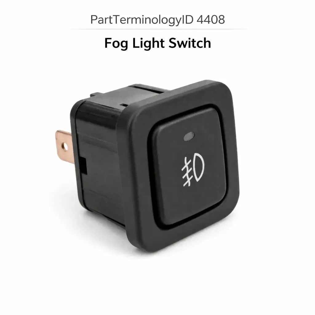
Fog Light Switch (PartTerminologyID 4408): Circuit Architecture, BCM Integration, and Front and Rear Fog Light Differentiation
Written by Arthur Simitian | PartsAdvisory
PartTerminologyID 4408, Fog Light Switch, is the driver-operated switch that activates the fog light circuit, controlling front fog lights, rear fog lights, or both simultaneously depending on the vehicle's fog light configuration and the switch's integrated function set, and communicating the driver's fog light command to the fog light relay, the body control module, or the exterior lighting control module through a direct relay signal, a switched ground input, or a serial bus digital command depending on the vehicle's exterior lighting architecture. That definition covers the fog light activation function correctly and leaves unresolved every question that determines whether the replacement switch is specified for front fog lights only, rear fog lights only, or a combined front and rear fog light assembly that controls both circuits from a single switch body, whether the switch is compatible with the headlamp interlock requirement that prevents fog light activation when the main headlamps are off on vehicles where fog light operation is restricted to headlamp-on conditions, whether the connector pin count and terminal assignment match the harness at the instrument panel, HVAC panel, or steering column stalk position, whether the switch is a momentary push-button type, a latching toggle type, or a rotary ring segment on a multifunction stalk, whether the switch includes an integrated indicator lamp that illuminates when the fog circuit is active, whether the replacement is compatible with the BCM's exterior lighting input circuit on vehicles where the BCM manages fog light activation and the switch sends only a request signal, whether the switch is rated for the fog light relay coil current or the full fog light lamp current depending on the circuit architecture, and whether the replacement must be programmed to the vehicle's exterior lighting module after installation.
It does not specify the fog light circuit coverage, headlamp interlock compatibility, connector pin count, switch type, indicator lamp type, BCM input compatibility, circuit current rating, or programming requirement. A listing under PartTerminologyID 4408 that states only year, make, and model without circuit coverage and BCM input compatibility cannot be evaluated by a technician replacing a failed fog light switch on a vehicle where the original switch sent a switched ground signal to the BCM's front fog light input pin and the BCM activated the fog light relay through its own output stage, and the replacement is a direct relay switch that connects the fog light relay coil supply to battery voltage directly when pressed, bypassing the BCM entirely and producing a fog light that activates but does not respect the BCM's headlamp interlock logic or the vehicle's ambient light sensor input that would normally inhibit fog lights in daylight conditions.
For sellers, PartTerminologyID 4408 is the exterior lighting PartTerminologyID where the headlamp interlock requirement is the most commonly misunderstood attribute, because fog light switches from different trim levels and production generations on the same platform may look physically identical and share the same connector body while differing in whether the switch includes a headlamp interlock circuit that prevents fog light activation when the main headlamps are off. Installing a non-interlock switch in an interlock-required position allows the driver to activate the fog lights with the headlamps off, which may be a legal violation in jurisdictions where fog lights may only be used in conjunction with headlamps, and in some countries is a specific roadworthiness requirement that will fail an inspection.
What the Fog Light Switch Does
Front Fog Light Circuit and the Headlamp Interlock Function
Front fog lights are short-range, wide-beam lighting units mounted below the main headlamps that improve road surface visibility in fog, rain, and snow by directing light at a low angle that reduces back-scatter from suspended water droplets. Most vehicle manufacturers restrict front fog light operation to headlamp-on conditions by incorporating a headlamp interlock in the fog light circuit: the fog light relay coil circuit is powered only when the headlamp relay is energized, preventing the fog lights from activating when the headlamps are off. The fog light switch in an interlock circuit is not in the power path of the fog lights directly; it signals the BCM or closes a relay control circuit that is itself powered from the headlamp circuit.
The headlamp interlock is implemented in two common ways. In the first, the fog light switch's circuit is powered from the headlamp relay output so the switch can only close the fog light relay coil circuit when headlamp power is present at the switch supply pin. In the second, the fog light switch sends a request signal to the BCM, and the BCM's software enforces the headlamp interlock condition by checking the headlamp status before activating the fog light relay output. Both approaches produce the same driver experience (fog lights only work with headlamps on) through different circuit mechanisms.
A replacement switch that does not include the headlamp interlock power source connection will allow the fog lights to be activated with the headlamps off. This is not a safety-critical failure in the way a brake light fault is safety-critical, but it is a regulatory compliance issue in jurisdictions with fog light use laws and a potential inspection failure on vehicles subject to annual lighting checks.
Rear Fog Light Circuit and the European Market Requirement
Rear fog lights are high-intensity red lighting units mounted at the rear of the vehicle that warn following drivers of the vehicle's presence in heavy fog. Rear fog lights are mandatory equipment on vehicles sold in the European Union, the United Kingdom, and many other markets, and their use is regulated: they may only be activated in conditions of severely reduced visibility (typically defined as visibility below 100 meters in fog) and must be deactivated when visibility improves. Activating rear fog lights in clear conditions is a traffic violation in most EU member states because the high intensity red output can be mistaken for brake lights by following drivers.
Rear fog light switches on European-market vehicles include an interlock condition that prevents rear fog light activation when the main headlamps or position lamps are off, consistent with the regulatory requirement that rear fog lights may only be used in conjunction with the vehicle's forward lighting. Some rear fog light switch designs also include a maximum activation duration or a reminder chime that activates when the vehicle reaches a speed above the threshold where fog conditions are unlikely, reminding the driver to deactivate the rear fog light.
The front and rear fog light functions are often controlled by separate switches or by a combined switch with separate latching positions for each circuit. A replacement specified for front fog lights only will not cover the rear fog light circuit on vehicles equipped with rear fog lights. The fog light coverage (front only, rear only, or front and rear combined) must be stated as a mandatory attribute in every listing.
Multifunction Stalk Integration and the Fog Light Ring Segment
On many European and some domestic vehicles, the fog light switch is a rotary ring segment on the exterior lighting stalk, with a front fog position and a rear fog position as separate detents on the ring. The ring is rotated past the parking light and headlamp positions on the stalk to engage the fog light positions. In this configuration, the fog light function is not a standalone switch but an integral part of the headlamp stalk assembly.
Replacing the fog light function on a multifunction stalk requires replacing the complete stalk assembly rather than a standalone switch. A listing that covers a stalk-integrated fog light switch under PartTerminologyID 4408 must state that the replacement is a complete stalk assembly and must list all other functions integrated in the stalk, following the same multifunction stalk convention established in PartTerminologyID 4340 (Dimmer Switch). A buyer expecting a standalone fog light switch who receives a complete stalk assembly will be surprised by the scope of the replacement but cannot receive a standalone fog light switch for a stalk-integrated application.
BCM Input Circuit Architecture and the Switched Ground Signal
On vehicles with BCM-managed exterior lighting, the fog light switch sends a switched ground signal to the BCM's fog light input pin. The BCM receives the request, checks the headlamp interlock condition and any other regulatory conditions (ambient light sensor, vehicle speed, or manual interlock from a separate headlamp switch position), and activates the fog light relay through its own output stage if all conditions are met. The switch carries only the BCM input signal current (1 to 10 milliamperes) and has no direct connection to the fog light relay coil or the fog light lamp circuit.
A direct relay switch installed in a BCM input circuit will connect the fog light relay coil supply to the BCM's input pin through the relay coil resistance, drawing significantly more current through the BCM input pin than the pull-up circuit is designed to source. In less severe cases this overloads the BCM input pull-up resistor and produces a dim or non-functioning BCM indicator output. In more severe cases the excess current damages the BCM input stage, producing the same BCM damage scenario described in PartTerminologyID 4316 (Courtesy Light Switch) and PartTerminologyID 4360 (Door Jamb Switch). The circuit architecture must be confirmed before ordering any fog light switch.
Indicator Lamp Integration and the Active Fog Status Signal
Most fog light switches include an integrated indicator lamp or LED element that illuminates when the fog circuit is active, providing the driver with confirmation that the fog lights are operating. The indicator is powered from one of three sources: the fog light relay output (illuminates when the relay is energized), a separate BCM indicator output, or an internal switch indicator circuit powered independently of the fog light circuit.
The indicator lamp type and supply voltage must match the circuit providing the indicator signal. An LED indicator designed for 12-volt direct supply in a circuit providing a 5-volt BCM indicator output will produce dim or near-invisible illumination. An incandescent indicator in a low-current BCM output circuit will draw more current than the output is rated for and may damage the BCM output stage. The indicator voltage and current draw must be confirmed against the indicator circuit specification for the specific vehicle.
Why This Part Generates Returns
Buyers return fog light switches because the replacement is a direct relay type and the application uses a BCM input circuit, overloading the BCM input pull-up and producing a dim or non-functioning fog indicator after BCM input stage damage; the replacement does not include a headlamp interlock and the fog lights activate with the headlamps off on a vehicle where the interlock is a roadworthiness requirement; the switch covers front fog lights only and the vehicle has both front and rear fog lights requiring a combined switch output, leaving the rear fog light circuit permanently uncontrolled; the replacement is a standalone switch and the application uses a multifunction stalk where the fog function is a rotary ring segment, requiring the buyer to replace the entire stalk; the connector pin count is three and the harness at the instrument panel position has five pins covering front fog signal, rear fog signal, headlamp interlock supply, indicator feed, and ground, leaving the rear fog and indicator circuits unconnected; the LED indicator produces full-brightness illumination regardless of the instrument dimmer setting because the indicator is not integrated with the vehicle's PWM dimmer circuit; the replacement requires BCM programming after installation and the listing does not disclose this, leaving the fog lights non-functional until programming is completed; and the switch body mounting clip geometry is correct but the switch face profile does not match the surrounding instrument panel surface, leaving a 2mm step between the switch face and the panel bezel that is immediately visible to the driver.
Top Return Scenarios
Scenario 1: "Direct relay switch in BCM input circuit, BCM input pull-up overloaded, indicator dim after BCM input damage"
The buyer installs the replacement fog light switch at the instrument panel position. On first activation, the fog lights activate but the indicator lamp appears very dim. After several days the indicator does not illuminate at all even though the fog lights are functional. The replacement switch is a direct relay type that connects the fog relay coil supply to the BCM's input pin through the relay coil resistance, drawing 350 milliamperes through the BCM input pull-up circuit rated for 10 milliamperes. The pull-up resistor degrades over multiple activation events and eventually fails.
Prevention language: "Circuit architecture: [direct relay circuit, switch carries relay coil current / BCM input circuit, switch sends switched ground signal only]. This switch is the [circuit type]. A direct relay switch in a BCM input circuit draws 300 to 500 milliamperes through the BCM input pull-up rated for milliamp-level current, damaging the pull-up resistor and eventually the BCM input stage. Confirm wire gauge at the switch connector before ordering: 18 to 22 AWG indicates a BCM input circuit; 16 AWG or heavier indicates a direct relay circuit."
Scenario 2: "No headlamp interlock, fog lights activate with headlamps off, vehicle fails lighting inspection"
The buyer installs the replacement fog light switch. The fog lights activate when pressed regardless of headlamp state. The original switch included a headlamp interlock that required the headlamps to be on before the fog circuit was powered. The replacement does not include this interlock. At the annual roadworthiness inspection, the inspector activates the fog lights with the headlamps off and fails the vehicle for a missing headlamp interlock.
Prevention language: "Headlamp interlock: [included, fog circuit powered from headlamp relay output / not included, fog lights activate independently of headlamp state]. Verify the headlamp interlock requirement against the original switch specification. Vehicles in jurisdictions with fog light interlock roadworthiness requirements will fail inspection with a non-interlock replacement switch."
Scenario 3: "Front fog switch only, vehicle has rear fog lights, rear fog circuit permanently uncontrolled"
The buyer replaces the fog light switch on a European-specification vehicle with both front and rear fog lights. The listing covers the vehicle without specifying fog light coverage. The delivered switch covers front fog lights only with a two-pin connector. The harness at the switch position uses a four-pin connector covering front fog, rear fog, ground, and indicator. The rear fog pin is unconnected. The rear fog lights cannot be activated from the switch at any time.
Prevention language: "Fog light coverage: [front fog only / rear fog only / front and rear fog combined]. Connector pin count: [X] pins. This switch covers [coverage]. Verify the fog light coverage against the original switch and the vehicle's fog light equipment. A front-only switch in a front and rear fog application leaves the rear fog circuit permanently uncontrolled."
Scenario 4: "Standalone switch ordered for stalk-integrated fog application, no installation path"
The buyer's fog light ring segment on the exterior lighting stalk has broken detents. The listing covers the vehicle under the fog light switch PartTerminologyID without noting the stalk integration. The delivered unit is a standalone push-button fog light switch designed for instrument panel installation. The vehicle has no instrument panel mounting position for a standalone fog switch and no harness connector at an instrument panel position. The stalk must be replaced as a complete assembly to restore the fog light switching function.
Prevention language: "Switch type: [standalone instrument panel switch / multifunction stalk ring segment, complete stalk assembly required]. This application integrates the fog light switch into the exterior lighting stalk. The fog function cannot be replaced independently. The complete stalk assembly is the replacement unit for any fog function failure on this application."
Scenario 5: "Three-pin replacement in five-pin harness, rear fog and indicator circuits unconnected"
The replacement switch uses a three-pin connector covering front fog signal, ground, and headlamp interlock supply. The harness uses a five-pin connector adding rear fog signal and indicator supply. After installation, the front fog lights activate correctly. The rear fog lights do not respond to any switch input. The indicator does not illuminate when the fog circuit is active.
Prevention language: "Connector pin count: [X] pins covering [front fog signal, rear fog signal, headlamp interlock supply, indicator supply, ground]. Verify pin count against the original harness connector. A switch with fewer pins than the original leaves active circuits unconnected. On European-specification vehicles, the rear fog circuit is a regulated function and must be controllable from the switch."
Scenario 6: "LED indicator not dimmer-integrated, full brightness at all dimmer settings on night drive"
The buyer installs the replacement fog switch. All fog light functions operate correctly. At night, the fog switch indicator remains at full brightness regardless of the instrument panel dimmer setting, producing a noticeably brighter indicator than all surrounding panel controls at low dimmer settings.
Prevention language: "Indicator dimmer integration: [proportional PWM dimmer compatible / fixed brightness, not dimmer controlled]. Verify the dimmer integration requirement. A fixed-brightness indicator in an application where all panel controls dim proportionally will produce disproportionate brightness at low dimmer settings, which is conspicuous to the driver during night operation."
Scenario 7: "BCM programming required after installation, not disclosed, fog lights non-functional until programmed"
The buyer installs the replacement fog light switch on a vehicle where the exterior lighting module must register the new switch input address before accepting fog light commands. No fog light response occurs on any activation attempt after installation. The listing does not mention programming. The buyer cannot locate the dealer within service hours and returns the switch as defective. The switch is not defective. It requires initialization.
Prevention language: "Post-installation programming: [not required / required, exterior lighting module programming with [scan tool type]]. Failure to complete the required programming after installation will result in no fog light response on any switch input. Confirm scan tool availability before ordering."
Core Listing Attributes for PartTerminologyID 4408
PartTerminologyID: 4408
Component: Fog Light Switch
Fog light coverage: front only, rear only, or front and rear combined (mandatory, in title)
Circuit architecture: direct relay circuit or BCM input circuit (mandatory, in title)
Headlamp interlock: included or not included (mandatory)
Switch type: standalone panel switch, latching toggle, or multifunction stalk ring segment (mandatory)
Connector pin count with function mapping for each pin (mandatory)
Contact current rating for direct relay circuit types (mandatory)
Indicator lamp type: incandescent with supply voltage, or LED with compatibility (mandatory)
Indicator dimmer integration: PWM dimmer compatible or fixed brightness (mandatory)
Post-installation programming requirement (mandatory for BCM-managed exterior lighting systems)
Headlamp stalk assembly note for stalk-integrated fog applications (mandatory)
Year/make/model/submodel/trim/market specification (domestic or European for rear fog applications)
Note for production date range where circuit architecture changed from direct relay to BCM input
Note for market variants where rear fog equipment differs between domestic and European specifications
Catalog Checklist for ACES/PIES Teams
PartTerminologyID = 4408
Require fog light coverage in title: front only, rear only, or combined (mandatory)
Require circuit architecture in title: direct relay or BCM input (mandatory)
Require headlamp interlock: included or not included (mandatory)
Require switch type: standalone or stalk-integrated (mandatory)
Require connector pin count with function mapping (mandatory)
Require indicator lamp type and dimmer integration (mandatory)
Require programming disclosure for BCM-managed exterior lighting systems (mandatory)
Prevent circuit architecture omission: a direct relay switch in a BCM input circuit overloads the BCM input pull-up; architecture must be confirmed as the first attribute for all post-1998 applications
Prevent headlamp interlock omission: a non-interlock switch in an interlock-required application produces a roadworthiness inspection failure in interlock-mandate jurisdictions; interlock status must be stated for every listing
Prevent fog light coverage omission: a front-only switch in a combined front and rear fog application leaves the rear fog circuit permanently uncontrolled; coverage and pin count must both be confirmed
Prevent stalk integration omission: a buyer ordering a standalone switch for a stalk-integrated application has no installation path; stalk configuration must be stated when the fog function cannot be replaced independently
Prevent programming omission: a BCM-managed fog switch requiring initialization listed as plug-and-play produces a no-function result; programming requirement must be disclosed with the required scan tool specified
Differentiate from Fog Light Assembly (if cataloged): the fog light assembly is the lamp unit and housing; the fog light switch is the driver control input; both are in the fog light system but at different positions; a fog light that does not illuminate despite correct switch activation indicates a failed lamp, relay, or BCM output rather than a switch fault
Differentiate from Headlamp Switch (if cataloged): the headlamp switch controls main beam, high beam, and position lamp circuits; the fog light switch controls the dedicated fog lamp circuit; on vehicles where both functions are integrated in a multifunction stalk, the complete stalk is the replacement unit
FAQ (Buyer Language)
What is the headlamp interlock on a fog light switch and do I need it?
The headlamp interlock prevents the fog lights from activating when the main headlamps are off. The interlock is required by fog light use regulations in many countries and is a roadworthiness inspection item in the EU, the UK, and other markets. On vehicles in these markets, a replacement without the headlamp interlock will fail the lighting inspection. On US domestic vehicles, fog light use laws vary by state and the interlock may not be a legal requirement but was designed into the original system. Confirm whether the original switch included an interlock before ordering a replacement without one.
Why do my fog lights work but the indicator is not illuminating after I replaced the switch?
A working fog circuit with no indicator illumination after switch replacement indicates either a failed indicator lamp in the new switch, an indicator circuit pin that is unconnected due to a pin count mismatch, or a BCM indicator output that is not recognized by the new switch's indicator circuit. Confirm the indicator pin is connected at the switch harness connector and check the BCM's fog indicator output with a multimeter during fog circuit activation. If the output voltage is present at the pin but the indicator does not illuminate, the indicator element in the switch is failed.
My rear fog lights cannot be activated after replacing the switch. Is the switch defective?
An unresponsive rear fog circuit after switch replacement is most commonly caused by a front-only switch installed on a vehicle with both front and rear fog lights, leaving the rear fog output pin unconnected. Confirm the replacement switch's fog light coverage and connector pin count against the original. If the coverage and pin count match, test the rear fog relay coil circuit for continuity from the switch output pin to the relay coil before concluding the switch is defective.
Can I use the fog light switch independently of the headlamp switch to use the fogs as daytime running lights?
This depends on whether the original switch includes a headlamp interlock. If the interlock is present, the fog lights can only activate when the headlamps are on. Bypassing the interlock to use the fogs as independent daytime lights may violate fog light use laws in your jurisdiction and may produce a roadworthiness inspection failure if the interlock is a required feature. Confirm the legal requirements in your jurisdiction before modifying the fog light interlock circuit.
Related PartTerminologyIDs
Fog Light Assembly (if cataloged): the lamp unit and housing the switch activates; a switch that produces the correct activation signal but the fog lamp does not illuminate indicates a failed lamp element, a failed relay, or a failed BCM output rather than a switch fault; confirm relay and lamp function before ordering a switch replacement
Headlamp Switch (if cataloged): the switch controlling main headlamp circuits; on vehicles where the headlamp and fog light functions are combined in a multifunction stalk, the complete stalk is the replacement unit for either function failure; confirm whether the fog and headlamp functions are combined or separate before ordering
Body Control Module (if cataloged): the module managing fog light activation on BCM-integrated exterior lighting systems; a BCM that does not activate the fog relay despite receiving the correct switch input signal indicates a BCM output fault or a missing headlamp interlock condition rather than a switch fault; confirm BCM input detection and interlock conditions with a scan tool before replacing the switch a second time
Exterior Lighting Control Module (if cataloged): on vehicles with a dedicated exterior lighting module separate from the BCM, the fog light switch communicates with the lighting module rather than the BCM directly; programming requirements and signal architecture specifications are specific to the lighting module rather than the BCM
Status in New Databases
PIES/PCdb: PartTerminologyID 4408, Fog Light Switch
PIES 8.0 / PCdb 2.0: No change in PartTerminologyID or terminology label
Final Take for PartTerminologyID 4408
Fog Light Switch (PartTerminologyID 4408) is the exterior lighting PartTerminologyID where fog light coverage (front only versus front and rear combined) and headlamp interlock status are the two attributes that most commonly produce returns with regulatory consequences, because a front-only switch in a front-and-rear application removes regulated rear fog control, and a non-interlock switch in an interlock-required application produces a roadworthiness inspection failure in interlock-mandate jurisdictions. The circuit architecture is the attribute with the highest consequence of hardware damage, because a direct relay switch in a BCM input circuit damages the BCM input stage in the same progression documented across courtesy light, door jamb, and defroster switch PartTerminologyIDs.
State the fog light coverage in the title. State the circuit architecture in the title. State the headlamp interlock status. State the switch type including multifunction stalk requirement. State the connector pin count with function mapping. State the indicator type and dimmer integration. State the programming requirement. For PartTerminologyID 4408, fog light coverage, headlamp interlock status, and circuit architecture are the three attributes that prevent the three most consequential return scenarios in the fog light switch buyer population.