Electric Coolant Fan Kit Switch (PartTerminologyID 4404): Temperature Threshold Calibration, Kit Component Integration, and Fan Circuit Load Compatibility
Written by Arthur Simitian | PartsAdvisory
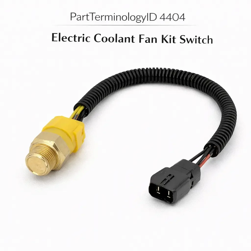
PartTerminologyID 4404, Electric Coolant Fan Kit Switch, is the thermostatic switch supplied as a component of an electric cooling fan conversion kit or a replacement fan assembly kit, designed to be installed in the coolant passage or radiator tank to activate the electric fan motor at a calibrated temperature threshold appropriate for the specific fan motor's airflow capacity and the engine's thermal management requirements, and distinguished from the standalone cooling fan switch (PartTerminologyID 4312) by its intended use as part of a multi-component kit where the switch, relay, wiring harness, and mounting hardware are engineered together to work as a matched system rather than as independent replacement components. That definition covers the kit-integrated fan switch function correctly and leaves unresolved every question that determines whether the replacement switch's temperature activation threshold is appropriate for the specific engine's normal operating temperature range and the fan kit's airflow capacity, whether the switch thread specification matches the coolant passage port or the bung fitting included in the kit, whether the switch contact current rating matches the relay coil current or the fan motor current it controls depending on whether the kit uses a relay-based circuit or a direct-switched circuit, whether the hysteresis band matches the kit's intended cycling behavior, and whether the switch is calibrated for an upgrade situation where the engine's normal operating temperature differs from the fan kit's design baseline.
It does not specify the activation threshold, thread specification, contact current rating, hysteresis band, or upgrade application temperature adjustment. A listing under PartTerminologyID 4404 that states only kit compatibility without specifying the activation threshold and thread specification cannot be evaluated by an engine builder installing an electric fan conversion on a hot rod or performance engine where the normal operating temperature runs 210 degrees Fahrenheit (99 degrees Celsius) rather than the standard 185 to 195 degrees Fahrenheit range, and the fan kit switch included in the kit is calibrated to activate at 185 degrees Fahrenheit, causing the fan to run continuously during normal operation at 210 degrees Fahrenheit rather than activating only when the engine exceeds the normal range.
For sellers, PartTerminologyID 4404 primarily serves the aftermarket electric fan conversion market, the performance cooling market, and the replacement switch market for buyers who have an existing fan kit but need to replace only the switch component. The buyer population includes performance builders selecting a threshold appropriate for a specific engine's calibrated operating temperature, restoration builders converting from belt-driven fans to electric fans on classic vehicles, and kit owners replacing a failed switch without replacing the entire kit.
What the Electric Coolant Fan Kit Switch Does
Kit-Integrated Versus Standalone Switch Considerations
The electric coolant fan kit switch differs from a standalone OEM cooling fan switch in two important respects. First, the thread specification may match a bung fitting included in the kit rather than any standard OEM coolant port, because fan conversion kits often include a radiator or coolant hose bung fitting that the builder installs to create a switch mounting point where none existed in the original cooling system. The switch thread must match the bung, not necessarily any OEM port specification. Second, the activation threshold must be selected based on the engine's actual operating temperature rather than an OEM specification, because performance and custom builds often run at temperatures different from factory calibration.
A fan kit switch with a 185 degree Fahrenheit activation threshold is correct for a stock engine calibrated to thermostat at 180 degrees. The same switch in a high-performance application running a 200 degree thermostat will activate the fan continuously during normal operation because the coolant never drops below the 185 degree activation threshold. The buyer must select the threshold based on the specific engine's operating temperature, not the kit's default specification.
Contact Configuration and Relay Circuit Architecture
Fan conversion kit circuits are built in two common configurations. The first uses the switch to carry the full fan motor current directly, without a relay. In this configuration the switch contacts must be rated for the full fan motor operating current, typically 15 to 30 amperes for a single electric fan motor. A switch rated for relay coil current only (typically 0.1 to 0.5 amperes) installed directly in a 20-ampere fan motor circuit will arc and weld its contacts on the first switching event.
The second and more common configuration uses the switch to carry only the relay coil current, with the relay's power contacts carrying the full fan motor current. In this configuration the switch contact rating of 1 to 5 amperes is adequate and the switch's primary specifications are the activation threshold and the thread specification. The kit instructions must specify which circuit architecture is used, and the replacement switch must match the contact rating appropriate for that architecture.
Hysteresis Band and Fan Cycling Behavior
The hysteresis band between the activation and deactivation thresholds determines the fan's cycling behavior. A narrow hysteresis band (3 degrees Fahrenheit or less) produces rapid on-off cycling when the coolant temperature is near the activation threshold, which is audible and accumulates relay wear. A wide band (15 degrees Fahrenheit or more) allows the coolant to rise significantly above the activation threshold before the fan deactivates, reducing cycling frequency but allowing the coolant to fluctuate over a wider range.
For fan kit applications, a hysteresis band of 8 to 12 degrees Fahrenheit is typical and provides stable cycling behavior at most operating conditions. A replacement switch with a narrower band than the kit's original will produce more frequent cycling at the same operating temperature, which the builder may notice as an increase in fan cycling audibility compared to the original kit behavior.
Top Return Scenarios
Scenario 1: "Activation threshold 25 degrees below engine operating temperature, fan runs continuously"
The builder selects a fan kit switch with a 185 degree Fahrenheit activation threshold for a performance engine running a 210 degree thermostat. The coolant temperature during normal operation remains above 185 degrees at all times, so the fan runs continuously from engine warm-up. The charging system carries the continuous fan load and the fan motor accumulates run hours far faster than designed for intermittent activation service.
Prevention language: "Activation threshold: [X] degrees Fahrenheit / [X] degrees Celsius. Select a threshold 10 to 15 degrees above the engine's normal operating temperature. A threshold below the normal operating temperature causes continuous fan operation during every drive, overloading the charging system and accumulating motor run hours beyond intermittent-service design limits."
Scenario 2: "Switch rated for relay coil current installed directly in fan motor circuit, contacts weld on first activation"
The kit uses a direct-switch circuit without a relay. The replacement switch is rated for 1 ampere relay coil current. The fan motor draws 22 amperes. On the first fan activation event, the switch contacts attempt to close under 22 amperes and arc across the contact gap, welding the contacts in the closed position. The fan runs continuously with no ability to deactivate until the circuit fuse is removed.
Prevention language: "Contact current rating: [X] amperes. Circuit architecture: [direct-switched fan motor circuit / relay-controlled circuit, switch carries relay coil current only]. Verify the circuit architecture in the kit instructions before ordering a replacement switch. A switch rated for relay coil current installed in a direct-switched fan motor circuit will weld its contacts on the first activation under full fan motor current."
Scenario 3: "Thread specification does not match kit bung fitting, switch cannot be installed in kit-supplied mounting point"
The kit includes a 3/8-18 NPT bung fitting installed in the radiator hose. The replacement switch uses an M14 x 1.5 metric straight thread. The switch cannot be threaded into the NPT bung. The builder must source a metric-to-NPT adapter or a correctly threaded replacement switch before the installation can proceed.
Prevention language: "Thread specification: [diameter x pitch, thread form]. Kit bung fitting thread: [specify if known]. Verify the thread specification against the bung fitting installed in the cooling system. Fan conversion kits use various bung thread specifications that may not match any standard OEM coolant port. Confirm the bung thread before ordering a replacement switch."
Core Listing Attributes for PartTerminologyID 4404
PartTerminologyID: 4404
Component: Electric Coolant Fan Kit Switch
Activation threshold in degrees Fahrenheit and Celsius (mandatory, in title)
Deactivation threshold and hysteresis band (mandatory)
Contact configuration: normally open or normally closed (mandatory)
Contact current rating in amperes (mandatory)
Circuit architecture compatibility: direct fan motor circuit or relay coil circuit (mandatory)
Thread specification: diameter, pitch, and thread form (mandatory)
Sealing method: crush washer, O-ring, or NPT thread sealant (mandatory)
Kit compatibility note: specific kit brand and model numbers where known (recommended)
Year/make/model or engine application for performance and upgrade builds
FAQ (Buyer Language)
How do I select the correct activation threshold for my engine?
Select a threshold 10 to 15 degrees Fahrenheit above the engine's normal full-operating-temperature coolant reading. If your engine runs at 195 degrees Fahrenheit at steady-state cruise, a switch activating at 205 to 210 degrees Fahrenheit will engage the fan only when the coolant rises above normal, which is the intended behavior for intermittent fan operation. Running a threshold below your normal operating temperature causes continuous fan operation.
My fan kit switch failed. Can I replace just the switch without buying the whole kit again?
Yes, provided you match the activation threshold, thread specification, and contact current rating of the original switch. Measure the original switch's thread with a thread pitch gauge before discarding it, confirm the threshold from the kit documentation or by measuring the original switch in a heated water bath, and confirm whether your kit circuit uses a relay or is direct-switched to determine the required contact current rating.
Related PartTerminologyIDs
Engine Cooling Fan Switch (PartTerminologyID 4312): the OEM standalone cooling fan switch for vehicles with factory electric cooling fans; the fan kit switch serves the same activation function but is supplied as part of an aftermarket kit with a bung fitting and relay rather than as a direct OEM port replacement
Cooling Fan Motor (if cataloged): the motor the switch activates; a switch that activates at the correct threshold but the fan motor does not run indicates a failed motor, a failed relay, or a wiring fault rather than a switch fault
Status in New Databases
PIES/PCdb: PartTerminologyID 4404, Electric Coolant Fan Kit Switch
PIES 8.0 / PCdb 2.0: No change in PartTerminologyID or terminology label
Final Take for PartTerminologyID 4404
Electric Coolant Fan Kit Switch (PartTerminologyID 4404) is the aftermarket fan conversion PartTerminologyID where the activation threshold must be selected based on the specific engine's operating temperature rather than a universal default, and a threshold calibrated for a stock 185 degree application will cause continuous fan operation on a performance engine running 210 degrees. State the activation threshold in the title. State the contact current rating and the circuit architecture compatibility. State the thread specification with thread form. For PartTerminologyID 4404, activation threshold selection relative to the specific engine's operating temperature, contact current rating against the circuit architecture, and thread specification matching the kit bung fitting are the three attributes that prevent the three most common return scenarios in the electric coolant fan kit switch buyer population.