HVAC System Switch (PartTerminologyID 4396): Control Architecture, Signal Type, and Multi-Function Integration Compatibility
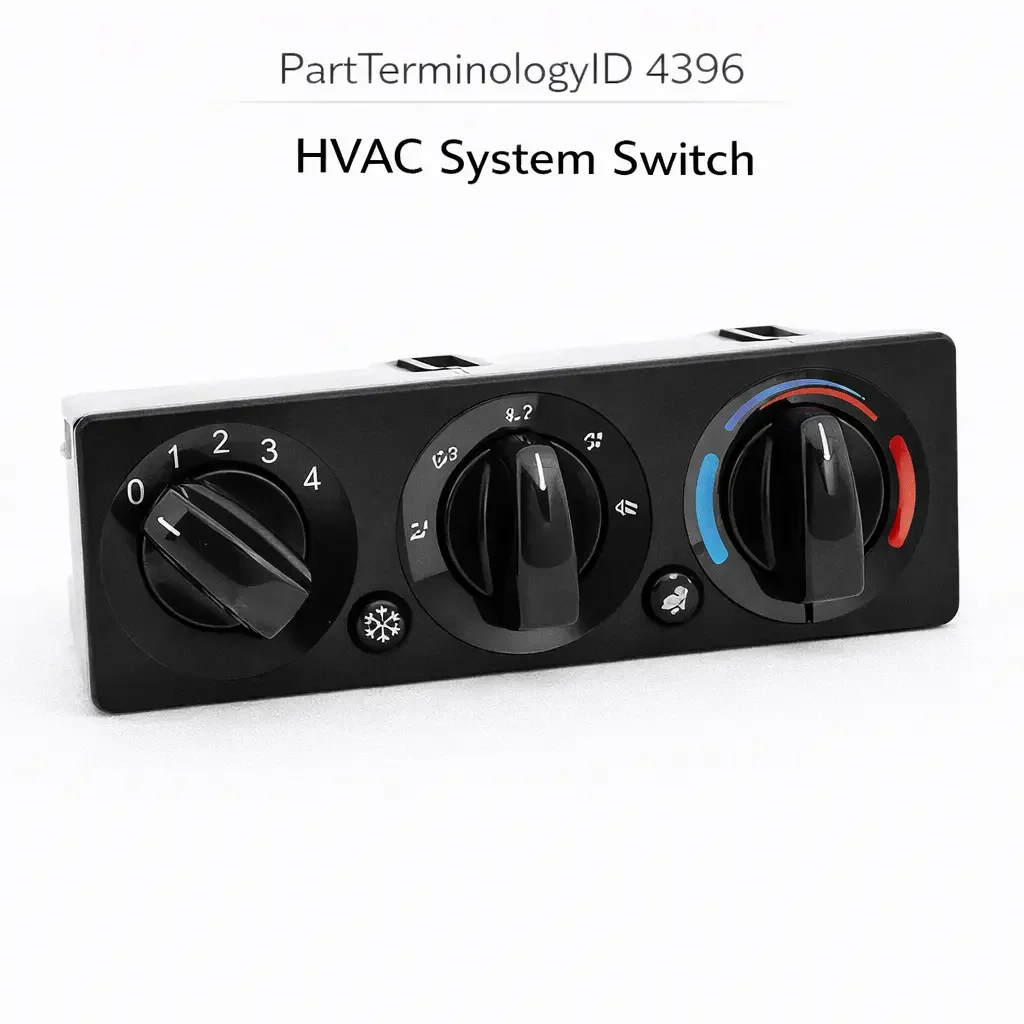
PartTerminologyID 4396, HVAC System Switch, is the driver-operated control device that provides the primary mode input to the vehicle's heating, ventilation, and air conditioning system, governing the selection of operating mode (heat, vent, defrost, A/C, bi-level, and combinations thereof), the activation and deactivation of the A/C compressor circuit, the selection of recirculated air versus fresh air intake, the fan speed setting, and in automatic climate control systems the temperature set point, all from a single integrated control panel or switch assembly that communicates the driver's climate commands to the HVAC control module, the blower motor resistor circuit, the mode door actuators, the blend door actuators, the A/C compressor clutch relay, and the recirculation door actuator. That definition covers the integrated climate command function correctly and leaves unresolved every question that determines whether the replacement switch assembly's signal architecture matches the original climate system's communication method (direct wired contact array, resistor network encoding, analog voltage output, serial bus digital command, or a combination of these methods for different functions on the same assembly), whether the connector pin count and terminal assignment match the harness at the instrument panel position, whether the switch body profile and mounting geometry match the instrument panel cutout and bezel, whether the replacement covers the same set of climate modes as the original including any vehicle-specific modes such as rear window defroster activation through the HVAC panel or integrated heated seat controls, whether the replacement is compatible with a manual climate control system or an automatic climate control system where the HVAC control module manages system operation and the switch assembly provides only set point and mode input commands, whether the illumination elements match the instrument panel lighting supply voltage and dimmer integration, and whether the switch requires programming or module initialization after installation on vehicles where the HVAC module must learn the new switch assembly's network address before accepting its commands.
It does not specify the signal architecture, connector pin count, switch body profile, mode coverage, climate system type, illumination compatibility, or programming requirement. A listing under PartTerminologyID 4396 that states only year, make, and model without signal architecture and mode coverage cannot be evaluated by a technician replacing a failed HVAC system switch on a vehicle where the original switch assembly communicated mode, temperature, and fan speed commands through a LIN bus serial protocol and the replacement is a direct-contact-array type from a lower trim level on the same platform, which produces no mode change response from the HVAC control module on any switch input because the module's LIN bus input receives no recognized serial commands from a switch that does not transmit a serial bus output.
For sellers, PartTerminologyID 4396 is the HVAC control PartTerminologyID with the broadest range of integrated functions of any switch PartTerminologyID in the climate control category, because a single HVAC system switch assembly may simultaneously control blower speed (covered separately by PartTerminologyID 4252), A/C compressor clutch engagement (covered by PartTerminologyID 4284 in part), mode door selection, blend door position, recirculation door position, rear defroster activation (covered separately by PartTerminologyID 4336), and in some assemblies heated seat and heated steering wheel activation, all from one integrated panel. A replacement that covers only a subset of these functions leaves the unaddressed functions non-operational, and the buyer will receive a panel that appears installed correctly but produces system faults across multiple climate and comfort functions simultaneously.
What the HVAC System Switch Does
Manual Climate Control Architecture and the Direct Signal Approach
In a manual climate control system, the HVAC system switch assembly provides direct control signals to each downstream actuator or relay independently. The mode selector routes battery voltage or a ground signal directly to the mode door actuator motor winding corresponding to the selected mode. The temperature control (blend door position) routes a variable resistance or voltage to the blend door actuator. The fan speed control connects the fan circuit to the appropriate resistor pack tap. The A/C button closes a relay coil circuit that energizes the compressor clutch relay. The recirculation button drives the recirculation door actuator directly.
In this architecture, the switch assembly carries or signals the full range of climate system actuator currents and carries a connector with enough pins to provide independent signal paths for each function. A typical manual climate switch assembly uses a 10 to 20 pin connector covering mode selection, temperature blend, fan speed, A/C activation, recirculation, ground returns, and illumination supply. Each function must be present and correctly mapped to the corresponding pin in the replacement assembly. A replacement with fewer active function outputs leaves the unmapped functions without a control signal.
The manual architecture is the most straightforward to diagnose and replace because each function is independently traceable on the harness connector. A mode that does not respond after replacement is caused by a specific pin or contact fault at the corresponding mode output, and the technician can identify the fault by checking continuity at the connector before attributing the non-function to the replacement assembly.
Automatic Climate Control Architecture and the Module-Managed Approach
In an automatic climate control system, the HVAC system switch assembly does not control the actuators directly. It sends mode, temperature set point, and fan speed requests to the HVAC control module, which manages all actuator positions and compressor control through its own output stage. The module uses feedback from cabin temperature sensors, solar load sensors, evaporator temperature sensors, and ambient temperature sensors to calculate the actuator positions needed to achieve the requested cabin condition, and adjusts these positions continuously without further input from the switch.
In this architecture, the switch assembly is an input device rather than a control device, and the signal it produces for each occupant input must match the format the HVAC control module expects. If the module uses analog resistance inputs for mode and temperature commands, the replacement switch must produce matching resistance values at each position. If the module uses a LIN bus or CAN bus digital interface, the replacement must transmit the correct message identifiers for each command on the vehicle network.
The failure modes of automatic climate control switch assemblies differ from manual assemblies. A failed button in a manual assembly disables one climate function. A failed bus communication from an automatic assembly disables every climate function simultaneously, because the module stops receiving commands and defaults to a safe mode where it holds the last known actuator positions. The occupant loses the ability to change any climate setting and the system appears frozen.
Serial Bus Signal Architecture and the Programming Requirement
On vehicles using LIN bus or CAN bus for HVAC panel communication, the switch assembly contains a microcontroller that encodes each button press and control input as a digital message on the network. The HVAC control module is programmed to accept messages from a specific node address or message identifier set. A replacement switch assembly that transmits messages using a different node address or message identifier set will not be recognized by the module, producing no climate response to any input.
Post-installation programming is required on some applications to register the new switch assembly's network address with the HVAC control module. This programming step is performed with a factory or compatible aftermarket scan tool and is not a routine part replacement procedure that the buyer can complete without specialized tools. The listing must disclose the programming requirement explicitly, noting the scan tool type required and whether the procedure is limited to factory tools or is available on compatible aftermarket platforms.
Some serial bus HVAC switch assemblies include an auto-initialization function where the module learns the new switch's network address on the first ignition cycle after installation without requiring scan tool intervention. The listing must distinguish between switches requiring scan tool programming and switches that self-initialize, because a buyer who orders a switch expecting plug-and-play installation and receives a scan-tool-programming-required unit will be unable to complete the installation without returning the switch or sourcing scan tool access.
Mode Coverage and the Function Set Verification Requirement
The HVAC system switch assembly's mode coverage defines the complete set of climate operating modes accessible from the panel. Mode coverage varies significantly between trim levels on the same platform. A base trim manual assembly may cover heat, bi-level, vent, floor-defrost blend, and defrost modes with a direct contact array. A mid-trim assembly on the same platform may add automatic mode and rear defroster activation from the HVAC panel. A top-trim automatic climate control assembly may add dual-zone independent temperature control, heated seat integration, heated steering wheel activation, and ventilated seat control, all from the same panel assembly with a higher pin count connector.
A replacement assembly specified for the base trim installed on a mid-trim vehicle will cover only the base trim mode set. Rear defroster activation, if previously controlled from the HVAC panel on the mid-trim vehicle, is no longer accessible. Heated seat controls, if integrated into the original assembly, are absent. The occupant loses access to these functions without any visible indication that the functions are absent until they attempt to activate them and find no response.
The mode coverage confirmation requires identifying the specific trim level and equipment package of the vehicle, not merely the model year and model name. Two vehicles of the same year, make, and model may have entirely different HVAC system switch assemblies if one is a base-trim manual system and the other is a top-trim dual-zone automatic system.
Dual-Zone Automatic Climate Control and Independent Zone Control Integration
Dual-zone automatic climate control systems provide independent temperature set points and mode control for the driver and passenger zones. The HVAC system switch assembly for a dual-zone system includes separate temperature controls and in some designs separate mode selectors for each zone, with the switch assembly communicating two independent set of climate commands to the HVAC module simultaneously.
A single-zone replacement assembly in a dual-zone application covers only the driver zone control. The passenger zone input is unconnected after replacement, leaving the passenger zone locked at the last module-stored set point with no ability to adjust from the panel. On a cold morning where the passenger previously set a warmer temperature than the driver, the passenger zone will continue delivering the previous setting regardless of any driver-side input.
The dual-zone versus single-zone distinction is not always apparent from a visual inspection of the replacement switch because dual-zone assemblies may appear only slightly more complex than single-zone assemblies, with an additional temperature control knob or display segment for the passenger zone. The zone configuration must be confirmed as a mandatory attribute for every listing covering platforms where both single-zone and dual-zone variants were produced.
Illumination Integration and the Instrument Panel Dimmer Compatibility
The HVAC system switch assembly's illumination elements (incandescent bulbs or LED backlights behind mode icons and control labels) are powered from the instrument panel lighting circuit and must be compatible with the specific circuit's supply voltage and dimmer architecture. Vehicles with PWM instrument dimmers require LED illumination elements designed for PWM dimming. Vehicles with resistive instrument dimmers require illumination elements compatible with the reduced voltage at the dimmer's output.
A replacement assembly with LED illumination elements designed for full battery voltage in a resistive dimmer circuit will produce bright illumination that does not respond proportionally to the dimmer control. A replacement with incandescent illumination in a circuit designed for LED current draw will draw excess current that may exceed the dimmer module's rated output and cause the dimmer module to reduce its output in thermal protection, dimming all instrument panel illumination below the driver's set level.
The illumination type and supply voltage compatibility must be confirmed for every HVAC system switch assembly listing, following the same conventions established in PartTerminologyID 4340 (Dimmer Switch).
Blend Door Actuator Signal Compatibility and the Analog Feedback Loop
Why the temperature control signal must match the actuator's input specification
In manual climate systems where the temperature blend door position is controlled by a variable resistance or voltage from the HVAC switch assembly, the blend door actuator motor receives its position command from the switch's temperature control output. The actuator contains a feedback potentiometer that reports the door's actual position back to the actuator control circuit, and the actuator drives the door to the position where the feedback potentiometer matches the switch's command position.
A replacement switch assembly with a temperature control output range that differs from the original will command the blend door actuator to positions that do not correspond to the labeled temperature settings on the control. A switch producing a 0 to 3.5 volt temperature control range in a system calibrated for a 0 to 5 volt range will command the blend door only through 70 percent of its full travel, leaving the fully counterclockwise (maximum heat) position of the switch corresponding to 70 percent blend door travel rather than the full heat position, and preventing the system from delivering maximum heat output at any switch position.
In automatic climate control systems, the blend door position is managed by the HVAC module based on the temperature set point command from the switch assembly and the sensor feedback loop. The switch assembly in this architecture sends only the set point command (the desired cabin temperature), and the module determines the blend door position independently. A replacement assembly producing incorrect set point commands in temperature units that do not match the module's calibration will deliver blend door positions that do not match the occupant's selected temperature on every operating mode.
Why This Part Generates Returns
Buyers return HVAC system switch assemblies because the replacement is a direct-contact-array manual type from the base trim level and the vehicle has a LIN bus automatic climate control system where the HVAC module receives no recognized bus commands from the non-serial replacement, producing no climate response on any input; the replacement covers single-zone control and the vehicle has dual-zone automatic climate control, leaving the passenger zone locked at the last stored set point; the mode coverage is missing the rear defroster activation mode present in the original mid-trim assembly, leaving the driver without panel access to the rear defroster function; the replacement requires LIN bus initialization with a factory scan tool and the listing describes it as plug-and-play, leaving the buyer with a non-functional climate system after installation; the connector is a 14-pin type and the harness at the instrument panel position is a 20-pin connector for the dual-zone assembly with heated seat integration, preventing full mating and leaving the heated seat and passenger zone circuits unconnected; the illumination elements are incandescent and produce excessive current draw on a circuit designed for LED illumination, causing the instrument panel dimmer module to reduce all panel illumination in thermal protection mode; the temperature control output range is 0 to 3.5 volts in a system calibrated for 0 to 5 volts, limiting the blend door to 70 percent travel and preventing maximum heat output; the switch body profile does not match the instrument panel cutout on the specific model year variant where the HVAC panel was reshaped at a production change point, leaving a visible gap at the lower edge of the installed assembly; and the replacement covers the single-screen display variant and the vehicle has the dual-screen climate display where the passenger zone set point is shown on a separate display driven by pins absent in the single-screen replacement connector.
Top Return Scenarios
Scenario 1: "Direct-contact-array switch in LIN bus automatic climate system, no mode response on any input"
The buyer's automatic climate control panel has failed with no illumination and no mode response. The listing covers the vehicle by year and model without specifying signal architecture. The delivered assembly is a direct-contact-array manual type from the base trim of the same platform. After installation, the HVAC control module continues displaying the last known climate settings because it receives no LIN bus commands from the new assembly. No mode change, temperature adjustment, or fan speed input produces any response. The module is functioning correctly and is waiting for bus commands that the manual assembly cannot produce.
Prevention language: "Signal architecture: [direct contact array, [X]-pin connector / LIN bus digital command / CAN bus digital command / analog resistance output]. This assembly uses [signal type]. Verify the signal architecture against the original assembly and the HVAC control module's input specification. A manual direct-contact assembly in an automatic climate control system produces no recognizable climate commands. The module will maintain the last stored climate state regardless of switch input."
Scenario 2: "Single-zone assembly in dual-zone application, passenger zone locked at last stored set point"
The buyer replaces the HVAC system switch on a dual-zone automatic climate control vehicle. The listing covers the model year without distinguishing zone configuration. The replacement is a single-zone assembly. After installation, the driver zone responds correctly to temperature, mode, and fan inputs. The passenger zone displays the previously stored temperature and cannot be changed from the panel. On a cold morning the passenger zone delivers 72 degree heating while the driver has set 68 degrees, and the passenger cannot adjust.
Prevention language: "Zone configuration: [single-zone / dual-zone with independent driver and passenger controls]. Connector pin count: [X] pins. This assembly covers [zone configuration]. A single-zone replacement in a dual-zone application leaves the passenger zone input unconnected. The HVAC module retains the last stored passenger zone setting indefinitely with no ability to adjust from the panel."
Scenario 3: "LIN bus assembly requires factory scan tool initialization, listed as plug-and-play, system non-functional after installation"
The buyer installs the replacement assembly. No climate response occurs on any input after installation. The HVAC module is not recognizing the new assembly on the LIN bus because the replacement requires factory scan tool programming to register its node address with the module. The listing states no programming is required. The buyer does not have access to a factory scan tool and must either source dealer programming or return the assembly.
Prevention language: "Post-installation programming: [not required, self-initializing on first ignition cycle / required, factory scan tool [specify tool] or compatible aftermarket tool with HVAC module programming capability]. Failure to complete the required initialization procedure will result in no climate response on any input after installation. Confirm scan tool availability before ordering."
Scenario 4: "Missing rear defroster mode, buyer loses panel access to rear defroster function"
The buyer's mid-trim HVAC assembly has a failed mode selector. The replacement is the base-trim assembly covering heat, vent, bi-level, and defrost modes. The original mid-trim assembly included a dedicated rear defroster activation button integrated into the HVAC panel. After replacement, the rear defroster cannot be activated from the HVAC panel. The buyer must reach across to the separate rear defroster switch (if present) or access the BCM through a scan tool to activate the rear defroster, neither of which was required with the original assembly.
Prevention language: "Mode coverage: [list all mode and function buttons included]. This assembly covers [mode list]. Verify the mode coverage against the original assembly's function set. Trim levels on the same platform may include rear defroster activation, heated seat controls, or ventilated seat controls integrated into the HVAC assembly that are absent in base-trim replacements."
Scenario 5: "20-pin dual-zone harness, 14-pin single-zone replacement, heated seat and passenger zone circuits unconnected"
The buyer installs the replacement single-zone assembly at the instrument panel position. The 14-pin replacement connector physically mates with the outer 14 positions of the 20-pin harness connector. After installation, the driver zone climate functions work. The passenger zone control circuit (pins 15 to 18) and the heated seat control circuit (pins 19 to 20) are unconnected. The passenger zone is locked and the heated seats do not respond to any activation attempt.
Prevention language: "Connector pin count: [X] pins. This assembly uses a [X]-pin connector. Verify the connector pin count against the vehicle harness. A replacement with fewer pins than the original leaves active circuits for passenger zone control, heated seat, or other integrated functions permanently unconnected."
Scenario 6: "Temperature output range 0 to 3.5 volts, system calibrated for 0 to 5 volts, blend door limited to 70 percent travel"
The buyer installs the replacement assembly. All modes respond correctly and fan speed changes work. The cabin never reaches maximum heat output even with the temperature control at full counterclockwise. A scan tool reveals the blend door actuator is receiving a maximum command of 3.5 volts, corresponding to 70 percent blend door travel rather than the 100 percent travel at the original switch's 5-volt maximum. The interior remains noticeably cooler than before the replacement on cold mornings.
Prevention language: "Temperature control output range: [X] to [X] volts or [X] to [X] ohms. Verify the output range against the blend door actuator's commanded input range. A replacement with a lower maximum output than the original limits the blend door's commanded travel range, preventing the system from delivering maximum heat or maximum cooling output at the switch's end positions."
Scenario 7: "Incandescent illumination in LED circuit, excess current triggers dimmer module thermal protection"
The buyer installs the replacement assembly. All climate functions operate correctly in daylight. At night, the instrument panel illumination dims below the driver's set level on the dimmer control. The replacement assembly uses four incandescent bulbs behind the mode icons drawing 1.8 amperes total. The instrument panel LED lighting circuit was designed for LED illumination drawing 0.3 amperes maximum. The PWM dimmer module's output stage reduces its duty cycle in thermal protection, dimming all connected instrument panel illumination including the speedometer, tachometer, and infotainment panel backlight below the driver's set brightness.
Prevention language: "Illumination type: [incandescent, [X] ampere total draw / LED, [X] ampere total draw, PWM dimmer compatible]. Verify the illumination type against the instrument panel lighting circuit's current capacity. An assembly with incandescent illumination in an LED-rated instrument lighting circuit will overload the dimmer module and reduce all instrument panel brightness in thermal protection."
Scenario 8: "Switch body profile does not match post-production-change instrument panel cutout, visible gap at lower edge"
The buyer's vehicle was produced after a mid-year production change where the HVAC panel cutout in the instrument panel was revised with a slightly different lower edge contour. The replacement assembly is specified for the pre-production-change cutout. The lower edge of the replacement body overhangs the panel opening by 3mm, preventing the assembly from sitting flush. The upper edges seat correctly but the lower edge has a visible offset against the surrounding panel surface.
Prevention language: "Production change note: this assembly is specified for [pre / post] production change vehicles. [Production change date or VIN break]. Verify the production change status of the specific vehicle before ordering. Assemblies produced before and after the panel cutout revision use different body contour profiles and are not interchangeable at the instrument panel cutout."
Core Listing Attributes for PartTerminologyID 4396
PartTerminologyID: 4396
Component: HVAC System Switch
Signal architecture: direct contact array, analog resistance, analog voltage, LIN bus, CAN bus, or combination (mandatory, in title)
Climate system type: manual or automatic climate control (mandatory, in title)
Zone configuration: single-zone or dual-zone (mandatory, in title for dual-zone applications)
Mode coverage: complete list of all modes and function buttons included (mandatory)
Connector pin count and terminal assignment with function mapping (mandatory)
Temperature control output range: voltage or resistance range (mandatory for manual types)
Fan speed step count and signal type (mandatory)
A/C activation circuit type: direct relay signal or module command (mandatory)
Rear defroster activation: included in assembly or absent (mandatory)
Heated seat integration: included or absent (mandatory where applicable)
Post-installation programming requirement: self-initializing or scan tool required with tool specification (mandatory for serial bus types)
Illumination type: incandescent with current draw, or LED with PWM compatibility and current draw (mandatory)
Switch body profile: production change note where cutout contour changed mid-year (mandatory where applicable)
Year/make/model/submodel/trim/equipment level
Note for trim levels where signal architecture differs on the same platform
Note for production VIN break where panel cutout or connector changed
Note for platforms where dual-zone and single-zone assemblies share outer housing dimensions
Catalog Checklist for ACES/PIES Teams
PartTerminologyID = 4396
Require signal architecture in title (mandatory)
Require climate system type in title: manual or automatic (mandatory)
Require zone configuration in title for dual-zone applications (mandatory)
Require complete mode coverage list (mandatory)
Require connector pin count with function mapping (mandatory)
Require temperature control output range for manual types (mandatory)
Require post-installation programming disclosure for serial bus types (mandatory)
Require illumination type and current draw (mandatory)
Prevent signal architecture omission: a direct-contact manual assembly in an automatic LIN bus system produces no climate response on any input; signal architecture is the first attribute to confirm and must be in the title without exception
Prevent zone configuration omission: a single-zone assembly in a dual-zone application locks the passenger zone permanently; zone configuration must be confirmed as a mandatory attribute on all platforms where both variants were produced
Prevent mode coverage omission: a base-trim assembly missing rear defroster, heated seat, or ventilated seat modes present in the original loses those functions permanently from the panel; full mode coverage list must be present in every listing
Prevent programming requirement omission: a serial bus assembly listed as plug-and-play that requires scan tool initialization leaves the buyer with a non-functional climate system; programming requirement must be disclosed and the required tool must be specified
Prevent illumination current draw omission: an incandescent assembly in an LED-rated instrument circuit overloads the dimmer module; illumination current draw must be stated for every assembly listing
Prevent production change body profile omission: assemblies produced before and after a panel cutout revision are not interchangeable; production change notes must be included for all applications with documented panel revisions
Differentiate from HVAC Blower Control Switch (PartTerminologyID 4252): the blower control switch governs fan speed only; the HVAC system switch assembly governs fan speed as one of multiple integrated climate functions; on vehicles where the fan speed is integrated into the HVAC system switch assembly, PartTerminologyID 4396 covers the complete assembly; on vehicles where the fan speed control is a separate switch, PartTerminologyID 4252 covers the standalone blower switch
Differentiate from Window Defroster Switch (PartTerminologyID 4336): the window defroster switch is a standalone switch for rear window defroster activation; when the rear defroster activation is integrated into the HVAC system switch assembly, PartTerminologyID 4396 covers the complete assembly; on vehicles where it is a separate switch, PartTerminologyID 4336 covers the standalone switch
Differentiate from A/C Clutch Switch (PartTerminologyID 4284): the A/C clutch switch is a pressure or temperature protection device in the refrigerant circuit; the HVAC system switch assembly provides the driver's A/C on/off command input; both affect compressor engagement but through different circuit positions for different purposes
FAQ (Buyer Language)
How do I identify whether my vehicle has a manual or automatic climate control system?
A manual climate control system has discrete physical controls for each function: a rotary or sliding mode selector, a separate temperature blend control, and a fan speed selector. Changes take effect immediately when the control is moved. An automatic climate control system has a temperature set point display (showing a specific temperature in degrees) and a single AUTO button or mode that allows the system to manage actuator positions automatically. If your climate panel shows a number like 68 or 72 rather than a gradient from cold to hot, you have automatic climate control.
Why does my HVAC system show no response after I installed the new switch assembly?
No response to any input after HVAC switch assembly replacement is the characteristic symptom of either a signal architecture mismatch (a direct-contact assembly in a bus-communication system or vice versa), a failed programming step on a serial bus assembly, or a connector mismatch leaving the primary communication pins unconnected. Confirm the signal architecture first. On a serial bus system, connect a scan tool and check whether the HVAC module detects a live bus signal from the switch assembly. If the module shows no switch input detected, the architecture mismatch or missing initialization is the cause.
My passenger zone temperature cannot be changed after I installed the new assembly. What happened?
An inability to change the passenger zone temperature after replacement is the direct result of a single-zone assembly installed on a dual-zone system. The passenger zone input circuit is present in the harness but is unconnected in the replacement assembly. The HVAC module retains the last stored passenger zone set point and has no new input to override it. The correct replacement is the dual-zone assembly with the passenger zone temperature control and the appropriate connector pin count for the full dual-zone circuit.
Does the HVAC system switch need programming after installation?
On direct-contact and analog signal architectures, no programming is required. On serial bus (LIN or CAN) architectures, programming may be required. The listing must specify whether self-initialization or scan tool programming is needed. If the listing is silent on the programming requirement for a vehicle with a serial bus climate architecture, assume programming is required and confirm with the supplier before completing the purchase.
Can I upgrade from a manual to an automatic climate control system by replacing only the switch assembly?
No. The switch assembly is one component of the climate control system. Automatic climate control also requires the HVAC control module calibrated for automatic operation, cabin temperature sensors, a solar load sensor, an evaporator temperature sensor, and blend door and mode door actuators programmed for module-controlled positioning. Replacing only the switch assembly with an automatic climate assembly on a manual climate system will produce no automatic functions because the underlying module and sensor hardware is absent.
Why is my instrument panel dimmer not working correctly after replacing the HVAC switch assembly?
Instrument panel dimmer issues after HVAC assembly replacement are caused by an illumination current mismatch. An incandescent replacement on an LED-rated circuit draws excess current and causes the dimmer module to reduce output in thermal protection, dimming everything on the circuit. An LED replacement designed for a resistive dimmer in a PWM dimmer circuit may not respond proportionally to the dimmer control. Confirm the illumination type and the circuit's current rating and dimmer architecture match before installing.
Related PartTerminologyIDs
HVAC Blower Control Switch (PartTerminologyID 4252): the standalone fan speed switch on vehicles where blower speed control is a separate switch rather than integrated into the HVAC system switch assembly; on vehicles with an integrated assembly, blower speed is covered by PartTerminologyID 4396
Window Defroster Switch (PartTerminologyID 4336): the standalone rear defroster switch on vehicles where defroster activation is not integrated into the HVAC assembly; on vehicles where the rear defroster is activated from the HVAC panel, PartTerminologyID 4396 covers that function within the assembly
A/C Clutch Switch (PartTerminologyID 4284): the refrigerant circuit pressure protection switches that disengage the compressor on pressure extremes; distinct from the driver's A/C activation command in the HVAC system switch assembly, which is the input side of A/C engagement rather than the protection side
HVAC Blower Motor Resistor (PartTerminologyID 4248 or similar): the resistance network downstream of the manual HVAC switch assembly that sets fan speed in resistor-based systems; a missing fan speed after HVAC switch assembly replacement that affects only specific speed positions may indicate a failed resistor pack rather than a switch mismatch
Blend Door Actuator (if cataloged): the motor driving the temperature blend door; a correctly functioning switch assembly with no temperature change response indicates a failed blend door actuator or actuator feedback potentiometer rather than a switch fault; confirm actuator function before attributing a no-temperature-change complaint to the switch assembly
Status in New Databases
PIES/PCdb: PartTerminologyID 4396, HVAC System Switch
PIES 8.0 / PCdb 2.0: No change in PartTerminologyID or terminology label
Final Take for PartTerminologyID 4396
HVAC System Switch (PartTerminologyID 4396) is the climate control PartTerminologyID with the broadest integrated function set and the widest range of signal architecture types of any switch in the HVAC category, and the consequence of a mismatch at the architecture level is total climate system non-function rather than the loss of a single mode or speed step. A direct-contact assembly in a LIN bus system produces zero climate response on every input. A single-zone assembly in a dual-zone system locks the passenger zone permanently. A base-trim assembly in a mid-trim application removes panel access to rear defroster, heated seat, and other integrated functions that the occupant relied on before the replacement. A serial bus assembly listed as plug-and-play that requires scan tool initialization leaves the buyer unable to complete the installation without returning the part.
State the signal architecture in the title. State the climate system type in the title. State the zone configuration in the title for dual-zone applications. State the complete mode coverage list. State the connector pin count with function mapping. State the temperature control output range. State the programming requirement for serial bus types. State the illumination type and current draw. State the production change notes where panel cutout or connector changed mid-year. For PartTerminologyID 4396, signal architecture, zone configuration, and mode coverage are the three attributes that prevent the three most consequential and most common return scenarios in the HVAC system switch buyer population.