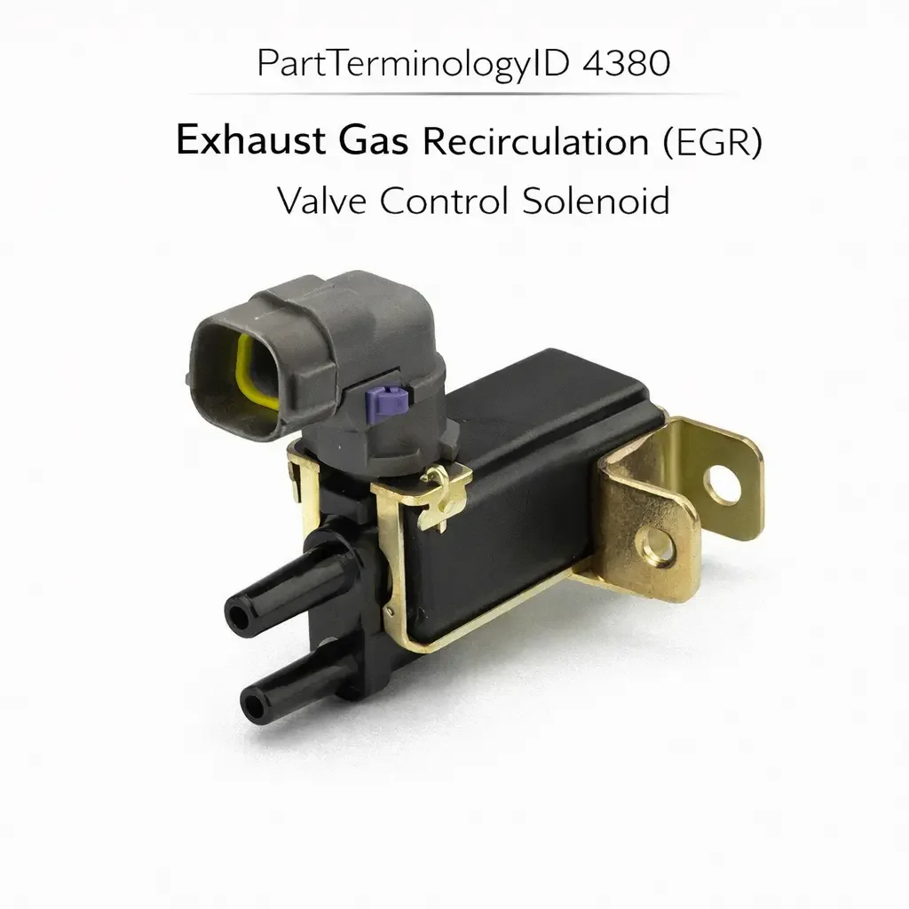
Exhaust Gas Recirculation (EGR) Valve Control Solenoid (PartTerminologyID 4380): Duty Cycle Compatibility, Vacuum Flow Configuration, and ECU Signal Architecture
Written by Arthur Simitian | PartsAdvisory
PartTerminologyID 4380, Exhaust Gas Recirculation (EGR) Valve Control Solenoid, is the electrically operated solenoid valve mounted in the vacuum or pressure circuit between the engine vacuum source and the EGR valve that modulates the vacuum or pressure signal delivered to the EGR valve diaphragm in response to a duty-cycle signal from the ECU, allowing the ECU to precisely control the EGR valve's opening position and the volume of exhaust gas recirculated into the intake manifold across the full range of engine operating conditions rather than relying on a fixed vacuum threshold as in earlier on-off EGR systems. That definition covers the ECU-controlled EGR modulation function correctly and leaves unresolved every question that determines whether the replacement solenoid's internal orifice size and flow characteristics match the original's vacuum delivery rate to the EGR valve diaphragm, whether the solenoid is a normally open type that passes vacuum when de-energized or a normally closed type that blocks vacuum when de-energized, whether the solenoid's duty cycle operating range matches the ECU's PWM output frequency and duty cycle range for the EGR control channel, whether the solenoid connector pin count and terminal type match the harness at the intake manifold or EGR valve mounting position, whether the solenoid is a single-port bleed type that controls vacuum by venting to atmosphere or a two-port switching type that routes vacuum between two circuit paths, and whether the solenoid coil resistance matches the ECU's output driver's expected load for proper current regulation through the solenoid coil.
It does not specify the normally open or normally closed configuration, duty cycle range, connector pin count, port configuration, or coil resistance. A listing under PartTerminologyID 4380 that states only year, make, and model without solenoid configuration and coil resistance cannot be evaluated by a technician replacing a failed EGR control solenoid on a vehicle where the original solenoid had a coil resistance of 26 ohms and the replacement has a coil resistance of 14 ohms, causing the ECU's output driver to source twice the design current through the solenoid coil on every duty cycle pulse, overloading the output driver transistor within weeks and producing an ECU output failure that the technician will initially attribute to a second solenoid failure rather than an ECU damage event caused by the coil resistance mismatch.
For sellers, PartTerminologyID 4380 is the EGR system PartTerminologyID with the most consequential impact on ECU hardware integrity of any EGR component, because a coil resistance mismatch that overloads the ECU's output driver does not produce an immediate visible failure but accumulates thermal stress in the output driver transistor over dozens of drive cycles before the transistor fails. The buyer who replaces the solenoid a second time after the ECU driver failure will find the second replacement also non-functional because the ECU can no longer drive the solenoid regardless of the solenoid's own condition. The coil resistance must be the first confirmed specification after the application fitment check.
What the EGR Valve Control Solenoid Does
ECU-Controlled EGR Modulation and the Duty Cycle Signal
Earlier EGR systems used a fixed-threshold vacuum switch to deliver either full vacuum or no vacuum to the EGR valve depending on whether temperature and throttle position conditions were met. This on-off approach provided only coarse EGR control with the recirculation rate determined by the EGR valve's own vacuum-to-opening calibration rather than by the ECU. On modern engines, the ECU controls the EGR valve opening position precisely by modulating the vacuum delivered to the valve diaphragm through the EGR control solenoid.
The ECU outputs a pulse-width-modulated signal to the solenoid coil, switching the solenoid on and off at a fixed frequency (typically 10 to 30 Hz) with a variable duty cycle (the percentage of each cycle the solenoid is energized). At a 0 percent duty cycle the solenoid is continuously de-energized. At 100 percent duty cycle it is continuously energized. At intermediate duty cycles the solenoid switches rapidly between its energized and de-energized states, producing an average vacuum delivery to the EGR valve diaphragm that is proportional to the duty cycle. The EGR valve opens to a position proportional to the average vacuum, and the ECU adjusts the duty cycle in closed-loop feedback based on the EGR position sensor or the ECU's estimated EGR flow.
The solenoid's response to the duty cycle signal depends on the match between the solenoid's internal flow characteristics, its normally open or normally closed configuration, and the ECU's duty cycle output range. A solenoid with different flow characteristics than the original will deliver a different average vacuum to the EGR valve diaphragm at the same duty cycle, causing the EGR valve to open more or less than the ECU commands and producing either under-EGR (elevated NOx, potential pinging) or over-EGR (rough idle, hesitation, elevated hydrocarbon emissions).
Normally Open versus Normally Closed Configuration
A normally open EGR control solenoid passes vacuum through its ports when de-energized and blocks or diverts vacuum when energized. In this configuration, the ECU's duty cycle controls how much of the vacuum source's output is blocked: at 0 percent duty cycle (solenoid always de-energized), full vacuum reaches the EGR valve and the valve opens to its maximum vacuum-commanded position. At 100 percent duty cycle (solenoid always energized), vacuum is blocked and the EGR valve closes. At intermediate duty cycles, the solenoid modulates the vacuum between these extremes.
A normally closed solenoid blocks vacuum when de-energized and opens when energized. In this configuration, the ECU's duty cycle controls how much vacuum is passed: at 0 percent duty cycle, no vacuum reaches the EGR valve and the valve is closed. At 100 percent duty cycle, full vacuum reaches the valve. The ECU's duty cycle output is calibrated for the specific solenoid configuration, and a normally closed solenoid in a circuit designed for a normally open solenoid will produce inverted EGR behavior: the EGR valve opens when the ECU commands closed and closes when the ECU commands open.
Coil Resistance and ECU Output Driver Protection
The solenoid coil resistance determines the current drawn from the ECU's output driver transistor at the supply voltage. At 12 volts, a 26-ohm coil draws approximately 460 milliamperes. A 14-ohm coil draws approximately 860 milliamperes from the same supply. The ECU's output driver is designed for a specific current range, and exceeding its maximum rated current produces heat in the transistor's junction at a rate proportional to the current excess. The transistor's thermal protection may activate briefly, causing the ECU to stop driving the solenoid temporarily and log a fault code, or may not activate in time to prevent progressive junction degradation if the excess current is sustained across multiple drive cycles.
The coil resistance is not typically printed on the solenoid body and must be confirmed from the original part number's specification or measured on the original failed solenoid before it is discarded. Measuring the original solenoid's coil resistance with a multimeter before ordering the replacement takes less than one minute and prevents the ECU output driver damage scenario that requires ECU replacement.
Single-Port Bleed versus Two-Port Switching Configurations
The EGR control solenoid is produced in single-port and two-port configurations. The single-port bleed type has one vacuum inlet port and one atmosphere vent port. When energized, the solenoid opens a bleed path to atmosphere, reducing the vacuum delivered to the EGR valve proportionally. When de-energized, the bleed path is closed and full vacuum reaches the EGR valve. This configuration modulates EGR valve opening by varying the degree of vacuum bleed-off.
The two-port switching type has one vacuum inlet port and one outlet port connected to the EGR valve. When energized, the solenoid connects the vacuum source to the EGR valve. When de-energized, it blocks the vacuum source and vents the EGR valve port to atmosphere, actively collapsing the vacuum at the valve diaphragm and closing the EGR valve quickly. The two-port configuration provides faster EGR valve closing response than the single-port bleed type, which is important on applications where the ECU commands rapid EGR closure during high-load or acceleration events.
A single-port bleed solenoid in a two-port switching circuit position leaves the EGR valve port without an active vent path, slowing EGR valve closing response and potentially allowing residual vacuum to hold the EGR valve partially open during high-load events where the ECU has commanded full closure.
Top Return Scenarios
Scenario 1: "Coil resistance 14 ohms, original was 26 ohms, ECU output driver fails within three weeks"
The buyer installs the replacement solenoid. EGR function appears normal for the first two weeks. The ECU's output driver transistor accumulates thermal stress from 860 milliamperes of coil current on every EGR duty cycle pulse rather than the 460 milliamperes it was designed for. After three weeks a P0403 or similar EGR circuit fault code is stored, the EGR system becomes inactive, and a second replacement solenoid also produces no EGR response because the ECU's output driver has failed. The technician replaces the solenoid a second time before identifying ECU damage as the root cause.
Prevention language: "Solenoid coil resistance: [X] ohms. Verify coil resistance against the original solenoid specification before ordering. Measure the original solenoid's coil resistance with a multimeter before discarding it. A replacement with lower coil resistance than the original draws higher current through the ECU output driver transistor, accumulating thermal stress that produces driver failure over multiple drive cycles."
Scenario 2: "Normally closed solenoid in normally open circuit, EGR opens when ECU commands closed"
The replacement is normally closed. The original was normally open. At engine idle where the ECU outputs a low duty cycle to minimize EGR recirculation, the normally closed solenoid keeps the vacuum path closed and the EGR valve shuts, which matches the intended behavior at that duty cycle by coincidence. At cruise where the ECU outputs a higher duty cycle to increase EGR flow, the normally closed solenoid opens the vacuum path and the EGR valve opens. The overall behavior appears roughly correct until the ECU commands maximum EGR closure at full throttle: the 100 percent duty cycle fully energizes the solenoid, opening the vacuum path completely and driving the EGR valve to full open during the acceleration event, causing severe hesitation and misfire.
Prevention language: "Solenoid configuration: [normally open / normally closed]. Verify the configuration against the original solenoid. The ECU's duty cycle output is calibrated for a specific solenoid configuration. A normally closed solenoid in a normally open circuit inverts the EGR valve response to the ECU's duty cycle commands, producing EGR over-flow during acceleration events when the ECU commands minimum EGR."
Scenario 3: "Single-port bleed solenoid in two-port switching application, slow EGR valve closing, hesitation on acceleration"
The replacement is a single-port bleed type. The application uses a two-port switching solenoid that actively vents the EGR valve port to atmosphere when de-energized to ensure rapid valve closure. With the single-port bleed solenoid, the EGR valve port has no active vent path when the solenoid is de-energized. Residual vacuum at the EGR valve diaphragm bleeds down slowly through the vacuum circuit's own leakage path rather than being actively collapsed. During rapid throttle applications, the EGR valve remains partially open for 0.5 to 1.5 seconds after the ECU has commanded closure, producing a lean hesitation on every hard acceleration.
Prevention language: "Port configuration: [single-port bleed / two-port switching with active EGR valve vent]. Verify the port configuration against the original solenoid. A single-port bleed solenoid in a two-port switching application lacks the active vent path that collapses EGR valve vacuum on command. Residual vacuum holds the EGR valve partially open after commanded closure, producing hesitation during rapid acceleration."
Scenario 4: "PWM frequency mismatch, ECU outputs 16 Hz, replacement solenoid rated for 10 Hz maximum, solenoid coil overheats"
The ECU's EGR control channel outputs a 16 Hz PWM signal. The replacement solenoid's coil and plunger assembly is rated for a maximum switching frequency of 10 Hz. At 16 Hz the solenoid's magnetic circuit does not have sufficient time between pulses to fully release the plunger before the next energization pulse arrives, causing the plunger to oscillate without completing full travel in either direction. The coil dissipates more heat than at the rated frequency because the incomplete mechanical cycles increase the average coil energization period. The solenoid coil overheats within 45 minutes of sustained EGR control operation.
Prevention language: "PWM operating frequency range: [minimum to maximum Hz]. Verify the solenoid's rated frequency range against the ECU's EGR control output frequency. A solenoid rated for a lower maximum frequency than the ECU's output will not complete full plunger travel between pulses, causing partial modulation and coil overheating during sustained EGR operation."
Core Listing Attributes for PartTerminologyID 4380
PartTerminologyID: 4380
Component: EGR Valve Control Solenoid
Solenoid configuration: normally open or normally closed (mandatory, in title)
Port configuration: single-port bleed or two-port switching (mandatory)
Coil resistance in ohms (mandatory)
PWM operating frequency range in Hz (mandatory)
Connector pin count and terminal type (mandatory)
Supply voltage: 12 volt or 5 volt reference (mandatory)
Mounting position: inline vacuum circuit or integral to EGR valve assembly (mandatory)
Year/make/model/engine
Catalog Checklist for ACES/PIES Teams
PartTerminologyID = 4380
Require solenoid configuration in title: normally open or normally closed (mandatory)
Require coil resistance in ohms (mandatory)
Require PWM frequency range (mandatory)
Require port configuration: single-port bleed or two-port switching (mandatory)
Require connector pin count (mandatory)
Prevent coil resistance omission: a replacement with lower coil resistance than the original overloads the ECU output driver transistor and produces ECU damage over multiple drive cycles; coil resistance is the first specification to confirm before any other fitment attribute
Prevent configuration omission: a normally closed solenoid in a normally open circuit inverts EGR valve response to ECU commands, producing over-EGR during acceleration events; configuration must be in the title
Prevent port configuration omission: a single-port bleed solenoid in a two-port switching application lacks the active EGR valve vent path, causing slow valve closure and acceleration hesitation
Prevent PWM frequency omission: a solenoid rated below the ECU's output frequency will not complete full plunger travel between pulses and will overheat during sustained EGR operation
Differentiate from EGR Valve (PartTerminologyID 4218 or similar): the EGR valve is the flow control device that opens to admit exhaust gas; the EGR control solenoid modulates the vacuum signal commanding the EGR valve's position; both are in the EGR circuit but at different positions with different failure symptoms
FAQ (Buyer Language)
How do I confirm the coil resistance of my original solenoid before ordering?
Set a multimeter to resistance mode and probe the two solenoid connector terminals on the original solenoid before discarding it. A reading between 10 and 40 ohms is typical for automotive EGR control solenoids. Record this value and confirm the replacement listing states a matching coil resistance before ordering. This single measurement prevents the ECU output driver damage scenario.
My EGR fault code returns within days of replacing the solenoid. What should I check?
A recurring EGR fault code after solenoid replacement indicates either the coil resistance mismatch has already damaged the ECU output driver (confirmed by measuring the voltage at the solenoid connector during a commanded EGR event with a scan tool), a vacuum leak in the EGR circuit preventing the solenoid from delivering vacuum to the EGR valve, or an EGR valve diaphragm failure that prevents the valve from responding to vacuum. Confirm the ECU output driver function before ordering a second solenoid.
What is the difference between the EGR control solenoid and the EGR valve itself?
The EGR control solenoid is the electrically controlled vacuum modulator between the vacuum source and the EGR valve. The EGR valve is the mechanical flow control device that opens a passage between the exhaust and intake manifolds when vacuum is applied to its diaphragm. A failed solenoid produces incorrect vacuum at the EGR valve and incorrect EGR flow as a result. A failed EGR valve diaphragm produces no EGR flow even with correct vacuum at the valve port.
Related PartTerminologyIDs
EGR Valve (PartTerminologyID 4218 or similar): the downstream device the solenoid controls; a correctly functioning solenoid with no EGR flow response indicates a failed EGR valve diaphragm or a stuck EGR valve passage; test the EGR valve by applying direct vacuum to the valve port before ordering a solenoid replacement
Engine Coolant Temperature Vacuum Control Switch (PartTerminologyID 4308): on applications where the EGR control solenoid works in combination with a temperature vacuum switch, both components must function correctly for proper EGR operation; a failed temperature switch can mask solenoid function by blocking vacuum upstream of the solenoid
EGR Time Delay Switch (PartTerminologyID 4376): the delay switch inhibits the EGR circuit in the post-start period; on applications where both the delay switch and the control solenoid are in series in the EGR vacuum circuit, failure of either component produces no EGR function; confirm which component is at fault before ordering a replacement
Status in New Databases
PIES/PCdb: PartTerminologyID 4380, EGR Valve Control Solenoid
PIES 8.0 / PCdb 2.0: No change in PartTerminologyID or terminology label
Final Take for PartTerminologyID 4380
EGR Valve Control Solenoid (PartTerminologyID 4380) is the EGR system PartTerminologyID where the coil resistance is the attribute with the highest consequence of mismatch, because an undersized coil resistance damages the ECU output driver over multiple drive cycles and converts a solenoid replacement into an ECU replacement. The solenoid configuration is the second most consequential attribute because a normally closed solenoid in a normally open circuit inverts EGR valve response to ECU commands in a way that is not immediately obvious but produces severe hesitation during full-throttle acceleration events. State the coil resistance first. State the solenoid configuration in the title. State the port configuration. State the PWM frequency range. For PartTerminologyID 4380, coil resistance, solenoid configuration, and PWM frequency range are the three attributes that prevent the three most consequential return scenarios in the EGR valve control solenoid buyer population.