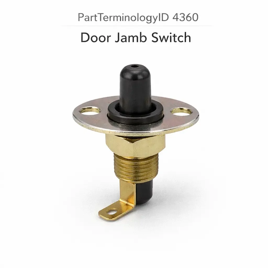
Door Jamb Switch (PartTerminologyID 4360): Plunger Travel, Circuit Architecture, and Body Control Module Compatibility
Written by Arthur Simitian | PartsAdvisory
PartTerminologyID 4360, Door Jamb Switch, is the switch mounted in the door pillar, door jamb, or door hinge area that detects the open and closed state of a vehicle door and triggers one or more downstream functions including interior courtesy lighting, door-ajar warning indicators in the instrument cluster, interior chime activation, security system door monitoring, body control module door status inputs, and in some applications automatic door lock engagement or dome light delayed shutoff timers. That definition covers the door position detection and multi-function triggering role correctly and leaves unresolved every question that determines whether the replacement switch's contact configuration matches the downstream circuit design at the specific door position, whether the plunger travel length matches the depth of engagement when the door presses the switch plunger to the fully depressed position at door close, whether the switch body thread specification or push-in clip geometry matches the mounting hole in the door pillar or hinge pillar, whether the switch is compatible with the body control module's input circuit on vehicles where the BCM monitors door position through a switched ground signal rather than carrying lamp or chime circuit current directly, whether the switch covers a single output circuit or multiple output circuits for different downstream functions activated simultaneously on door open, whether the switch plunger head profile matches the contact geometry at the installation point, whether the replacement switch is rated for the expected door cycling frequency at the specific position, and whether the switch includes an integrated resistor for door position encoding on vehicles where the BCM identifies specific door positions by measuring resistance rather than detecting a simple ground closure.
It does not specify the contact configuration, plunger travel length, thread or clip mounting specification, BCM input compatibility, output circuit count, plunger head profile, cycle rating, or integrated resistor encoding. A listing under PartTerminologyID 4360 that states only year, make, and model without contact configuration and plunger travel cannot be evaluated by a technician replacing a failed driver-side door jamb switch on a vehicle where the plunger travel required for full depression at door close is 12mm and the replacement switch has a 10mm maximum plunger travel, leaving the plunger 2mm short of full depression with the door latched, which the BCM interprets as a door that is not fully closed and activates the door-ajar warning and the interior chime continuously while the vehicle is driven.
For sellers, PartTerminologyID 4360 covers the same door position detection function as PartTerminologyID 4316 (Courtesy Light Switch) and the two PartTerminologyIDs address the same physical switch in many catalog databases. The distinction in some catalogs is that PartTerminologyID 4316 specifically names the courtesy lighting activation function while PartTerminologyID 4360 covers the broader door position detection role that feeds multiple downstream functions simultaneously. Where both PartTerminologyIDs appear in the same catalog, the listing attributes, return scenarios, and prevention requirements are identical between the two, and the same switch body satisfies both PartTerminologyIDs on any given application. For sellers managing both PartTerminologyIDs, cross-referencing the listings and confirming that the attributes required for PartTerminologyID 4316 are also present in PartTerminologyID 4360 listings ensures both catalog entries serve the buyer correctly.
What the Door Jamb Switch Does
Multi-Function Door Position Detection and the Downstream Consequence of Each Output
The door jamb switch is the single sensor that feeds multiple downstream systems with door position data simultaneously. On a vehicle with a body control module, the BCM's door input pin receives a switched ground signal from the switch and uses this single input to activate the courtesy lamp output, start the interior chime timer, update the door status display in the instrument cluster, arm or disarm the perimeter alarm zone for that door, enable or disable the interior motion sensor zone, and in some applications release or engage the power door lock on the affected door. All of these functions depend on the same switch contact change, and a switch that produces an ambiguous or incorrect signal at any point in the door open and close cycle produces incorrect behavior across all of these functions simultaneously.
This multi-function dependency is what distinguishes the door jamb switch from most other body electrical switches. A failed cruise control switch disables one system. A failed door jamb switch produces symptoms across courtesy lighting, door-ajar warning, chime behavior, security system function, and in some vehicles automatic lock behavior all at once, which makes diagnosis confusing if the technician does not identify the common cause. Confirming the door jamb switch as the root cause before replacing any of the downstream components it feeds is the correct diagnostic sequence, and a listing that clearly describes all functions the switch activates helps the buyer confirm the switch is the correct replacement for the multi-symptom complaint.
BCM Input Circuit Architecture and the Switched Ground Signal Function
On vehicles with BCM-managed door position monitoring, the door jamb switch connects the BCM's door input pin to the chassis ground when the door is opened and disconnects it when the door is closed. The BCM maintains a pull-up voltage (typically 5 volts through an internal pull-up resistor) on the input pin. When the door opens and the switch connects the pin to ground, the pin voltage drops to near zero and the BCM detects an open-door state. When the door closes and the switch disconnects the pin from ground, the pin rises back to the pull-up voltage and the BCM detects a closed-door state.
This switched ground architecture means the switch carries only the BCM's low-level pull-up current (typically 1 to 5 milliamperes) rather than any lamp circuit or chime circuit current. The switch contact current rating requirement is therefore minimal in terms of current magnitude, but the contact must produce a clean, low-resistance ground connection when the door is open and a clean, high-resistance open connection when the door is closed. A switch with contaminated contacts that present 500 ohms to ground when the door is open will produce a partial ground that the BCM may interpret as an ambiguous door state, generating intermittent door-ajar warnings at random intervals while driving.
On pre-BCM vehicles with direct lamp circuits, the door jamb switch carries the full courtesy lamp current (0.5 to 2.0 amperes) and must be rated accordingly. The circuit architecture (BCM input or direct lamp circuit) is confirmed by the wire gauge at the switch connector, following the same diagnostic method described in PartTerminologyID 4316. A heavy gauge wire (16 AWG or thicker) indicates a direct lamp circuit. A light gauge signal wire (18 to 22 AWG) indicates a BCM input circuit.
Resistor-Encoded Door Position Identification
Some vehicles use a resistor-encoded door jamb switch where each door position (driver front, passenger front, driver rear, passenger rear) is identified by a unique resistor value integrated into the switch body. Instead of a simple ground closure, the switch presents a specific resistance value to ground when the door is opened: the driver front door switch might present 560 ohms, the passenger front 1200 ohms, the driver rear 2700 ohms, and the passenger rear 5600 ohms. The BCM measures the resistance at its door input pin and identifies which specific door is open based on the resistance value, allowing all four door switches to share a single BCM input wire rather than requiring four separate input pins.
A replacement switch for a resistor-encoded application must include the correct resistor value for the specific door position being replaced. A switch without a resistor (presenting 0 ohms to ground) in a resistor-encoded system will produce a resistance value that the BCM maps to no defined door position or to a different door position, causing incorrect door-ajar display information and potentially incorrect security system zone activation. The resistor value and the door position assignment must be stated in the listing for every resistor-encoded application.
Plunger Travel Length and the Door Close Engagement Geometry
The plunger travel is the distance the switch plunger moves from its fully extended (door open) position to its fully depressed (door closed) position. This distance must match the depth of engagement at the specific door jamb installation position: the distance between the switch plunger tip at rest and the surface of the door weatherstrip, door striker plate, or door jamb that contacts and depresses the plunger when the door closes.
A plunger that is too short (maximum travel less than the required engagement depth) cannot reach the fully depressed state when the door is closed. The switch contact remains in the door-open state with the door latched, producing a permanent false door-ajar condition. On a BCM-managed system, this permanent false open-door signal will illuminate the door-ajar indicator, sound the door-ajar chime, prevent the interior lights from extinguishing on a timed shutoff, and on some vehicles prevent the security system from arming fully because the perimeter zone for that door is not confirming a closed state.
A plunger that is too long (maximum travel greater than the required engagement depth) fully depresses before the door contacts the jamb seal and latches. This is generally acceptable unless the excess travel is large enough that the door cannot latch because the plunger is bottoming out in the switch body before the door striker engages the latch, which would prevent the door from closing at all. In most cases a slightly longer plunger travel than required produces correct switch behavior because the door closes fully and the plunger is fully depressed with travel to spare.
The plunger travel specification must be stated in mm for every door jamb switch listing, and the buyer must confirm the engagement depth at the specific door position before ordering. Engagement depth varies between front and rear door positions on the same vehicle and between driver and passenger sides on vehicles with asymmetric door seal geometry.
Mounting Specification: Threaded Body versus Push-In Clip
The door jamb switch mounts in the door pillar by one of two methods. The threaded body type uses a male thread that screws into a threaded insert or directly into the sheet metal of the door pillar. The most common thread specifications are 3/8-24 UNF and M10 x 1.0, with the thread engagement providing both the retention force and the precise positioning of the plunger tip relative to the door close surface.
The push-in clip type uses a cylindrical or rectangular body with spring retention tabs that snap into a round or slotted cutout in the door pillar sheet metal. The clip geometry (tab width, tab height, clip body diameter) must match the cutout dimensions exactly for the switch to be retained securely under the repeated impact force of door closing. A clip body that is too small for the cutout will allow the switch to rock in the cutout under each door close impact, producing a rattle and eventually allowing the switch to rotate out of position so the plunger is no longer aligned with the door contact surface.
The mounting type and full specification (thread or clip dimensions) must be stated for every door jamb switch listing. The two mounting types are not interchangeable at any installation position and a mismatch produces either a switch that cannot be installed (threaded body in a clip cutout) or a switch that falls out of position (clip body in a threaded hole without retention).
Contact Configuration and the Normally Open Versus Normally Closed Distinction
The contact configuration of the door jamb switch determines how the switch interacts with the downstream circuit. A normally open switch has contacts that are open when the door is closed (plunger depressed) and close when the door is opened (plunger extended), completing the circuit and activating the downstream function. This is the standard configuration for direct lamp circuits and most BCM input circuits.
A normally closed switch has contacts that are closed when the door is closed (plunger depressed) and open when the door is opened (plunger extended). This configuration is less common but is used on some European and Japanese applications where the circuit design relies on circuit interruption rather than circuit completion to signal door open. Installing a normally open switch in a normally closed application will produce the opposite lighting and signal behavior: the interior lights illuminate only when the door is closed and extinguish when the door is opened. Installing a normally closed switch in a normally open application produces the same reversed behavior.
The contact configuration must be confirmed against the vehicle's circuit diagram and stated explicitly in every listing. The most reliable field confirmation is to test the original switch with a continuity tester: if continuity is present with the plunger depressed and absent with the plunger extended, the switch is normally closed. If continuity is absent with the plunger depressed and present with the plunger extended, the switch is normally open.
Why This Part Generates Returns
Buyers return door jamb switches because the plunger travel is 2mm shorter than the required engagement depth and the BCM receives a permanent false open-door signal with the door latched, activating the door-ajar chime and indicator continuously while driving; the contact configuration is normally closed and the application requires normally open, illuminating the courtesy lights only while the door is fully closed and extinguishing them when the door is opened; the switch is a standard ground-closure type and the application uses resistor-encoded door position identification, causing the BCM to register an unknown door position or map the switch to the wrong door in the door status display; the thread is 3/8-24 UNF and the door pillar has a push-in clip cutout, making the threaded switch body impossible to install without drilling a new hole; the switch carries the full direct lamp circuit current rated at 0.5 amperes and the application connects both dome lights and a courtesy lamp to the same switch contact drawing 1.8 amperes total, producing arc erosion and intermittent contact failure within 2,000 door cycles; the BCM input circuit switch installs in the driver front position but is specified for the passenger front position with a different resistor value, causing the BCM to display the passenger front door as open when the driver front door is opened; the push-in clip body diameter is 13mm and the door pillar cutout is 16mm, allowing the switch to rotate under door closing vibration until the plunger is no longer aligned with the door contact surface; and the replacement does not include the grommet seal at the wire exit point and the installation position is in the lower door pillar where road splash enters the pillar cavity and contacts the switch body, producing corrosion at the switch terminals within six months.
Top Return Scenarios
Scenario 1: "Plunger 2mm short, BCM receives permanent false door-ajar signal, chime and indicator active while driving"
The buyer installs the replacement switch at the driver front door jamb. The door closes and latches normally from a mechanical standpoint. Immediately after closing the door, the door-ajar indicator illuminates in the instrument cluster and the door-ajar chime begins sounding. On the test drive the chime sounds continuously and the interior lights do not extinguish on the timed shutoff. The replacement plunger travel is 10mm maximum. The engagement depth at the driver front door jamb position on this vehicle is 12mm. The plunger is 2mm short of full depression at door close, leaving the BCM's door input pin connected to ground through the partially-engaged switch contact.
Prevention language: "Plunger travel: [X] mm from fully extended to fully depressed. Verify the engagement depth at the specific door jamb installation position before ordering. Door positions vary in engagement depth between front and rear and between driver and passenger sides. A switch with plunger travel shorter than the engagement depth will leave the BCM in an open-door state with the door fully latched, activating the door-ajar indicator, chime, and interior lighting continuously."
Scenario 2: "Normally closed switch in normally open circuit, courtesy lights on with door closed, off with door open"
The buyer installs the replacement at the passenger rear door jamb. With the door closed, the interior courtesy lights illuminate. When the door is opened, the lights extinguish. The BCM receives a door-closed signal (switch contact open) while the door is open and a door-open signal (switch contact closed) while the door is closed. All downstream functions triggered by the switch are reversed: the door-ajar chime sounds when the door is closed, the security zone shows closed when the door is open, and the dome light delayed shutoff timer starts when the door closes rather than when the door opens.
Prevention language: "Contact configuration: [normally open, contacts close on door open / normally closed, contacts open on door open]. Verify the contact configuration against the vehicle's door position circuit design. A normally closed switch in a normally open circuit reverses all door-state dependent functions simultaneously: courtesy lights, door-ajar warning, chime activation, and security zone status."
Scenario 3: "Standard ground closure switch in resistor-encoded application, BCM shows unknown door or wrong door as open"
The buyer replaces the driver rear door jamb switch on a vehicle where the BCM identifies each door position by resistance value. The replacement is a standard ground-closure type with no internal resistor. When the driver rear door is opened, the switch presents 0 ohms to ground. The BCM does not find a match in its resistance lookup table for 0 ohms (or maps it to a different door's resistance range) and displays a door-open indication for the wrong door in the cluster, or clears all door displays and logs a BCM input fault code.
Prevention language: "Switch encoding type: [standard ground closure / resistor-encoded, specify resistance value in ohms for this door position]. Verify the encoding type against the vehicle's BCM door input circuit. A standard ground-closure switch in a resistor-encoded system presents an undefined resistance value. The BCM cannot identify the specific door position and will display incorrect door status or log a fault code."
Scenario 4: "Threaded body switch in push-in clip cutout, switch cannot be installed without modifying door pillar"
The buyer's push-in clip door jamb switch has broken retention tabs. The listing covers the vehicle without specifying mounting type. The delivered switch has a 3/8-24 UNF threaded body. The door pillar has a 16mm round clip cutout with no thread. The threaded switch body cannot be secured in the clip cutout without drilling and tapping the cutout or installing a thread insert, neither of which is an acceptable repair on a finished door pillar.
Prevention language: "Mounting type: [threaded body, 3/8-24 UNF / push-in clip, specify clip body diameter and cutout shape]. Verify the mounting type against the door pillar installation position. Threaded and push-in clip mounting types are not interchangeable. A threaded body switch in a clip cutout cannot be retained and requires pillar modification to install."
Scenario 5: "Contact current rating 0.5 amperes, direct lamp circuit draws 1.8 amperes, arc erosion within 2000 cycles"
The buyer installs the replacement in a direct lamp circuit connecting two dome lights and a courtesy lamp. The total circuit current is 1.8 amperes. The replacement switch contact is rated for 0.5 amperes. On each door open event the contact closes under 1.8 amperes and on each door close event it opens under 1.8 amperes. The arc at the contact gap at each make-and-break event ablates the contact surface at a rate proportional to the current-to-rating excess. After 2,000 door cycles the contact surface erosion produces intermittent connection that the buyer describes as the dome light flickering when the door opens.
Prevention language: "Contact current rating: [X] amperes. Verify the total current draw of all lamp circuits connected to the switch in a direct lamp circuit application. Sum the current draw of all lamps and courtesy circuits simultaneously activated by the switch. A contact current rating below the total circuit current draw produces accelerated arc erosion and contact failure within a fraction of the rated service life."
Scenario 6: "Passenger front resistor value installed at driver front position, BCM displays wrong door in door status cluster"
The buyer replaces both the driver front and passenger front door jamb switches in the same service event, ordering two units from the same listing without noting that resistor-encoded switches have position-specific resistor values. Both switches have the same physical body and connector but different internal resistor values. The buyer installs the passenger front resistor switch at the driver front position and vice versa. The BCM displays the passenger front door as open when the driver front door is opened and the driver front door as open when the passenger front opens. All downstream functions are activated at the wrong door position.
Prevention language: "Door position: [driver front / passenger front / driver rear / passenger rear]. Resistor value for this position: [X] ohms. Resistor-encoded switches are position-specific. Installing the switch for one door position at a different door position causes the BCM to activate all downstream functions (lighting, chime, security zone) for the wrong door. Verify the resistor value matches the specific door position before installation."
Scenario 7: "Push-in clip body 13mm in 16mm cutout, switch rotates under door closing vibration, plunger misaligned"
The buyer installs the replacement switch in the B-pillar push-in clip cutout. Initial function tests confirm correct courtesy light behavior. After one week, the door-ajar warning illuminates intermittently while driving over rough roads. Inspection reveals the switch has rotated approximately 45 degrees in the 16mm cutout due to the 3mm clearance on each side of the 13mm clip body. The plunger is no longer perpendicular to the door close surface and contacts the door weatherstrip at an angle, producing off-center loading that varies the contact closure force with each door close event.
Prevention language: "Push-in clip body diameter: [X] mm. Required cutout diameter: [X] mm. A clip body smaller than the cutout by more than 1mm will rotate under door closing vibration. Rotation misaligns the plunger relative to the door close contact surface, producing variable contact closure force and intermittent door-ajar signals while driving."
Scenario 8: "No wire exit grommet, lower pillar position, road splash corrosion at terminals within six months"
The buyer installs the replacement switch at the lower door hinge pillar position without noting that the installation position is below the door seal drainage level. The replacement switch does not include the rubber grommet that seals the wire exit point in the pillar sheet metal. Road splash and drainage water entering the lower pillar cavity contact the unprotected wire entry point of the switch body. Terminal corrosion develops within six months, producing increasing contact resistance that first manifests as intermittent door-ajar warnings during wet weather before progressing to complete switch contact failure.
Prevention language: "Wire exit grommet: [included / not included, must be transferred from original or purchased separately]. Lower door pillar installation positions are exposed to road splash and drainage water. A switch installed at a lower pillar position without the wire exit grommet will develop terminal corrosion from moisture ingress within the first year of operation in wet climate or road splash environments."
Core Listing Attributes for PartTerminologyID 4360
PartTerminologyID: 4360
Component: Door Jamb Switch
Contact configuration: normally open or normally closed (mandatory, in title)
Circuit architecture: direct lamp circuit or BCM switched ground input (mandatory, in title)
Switch encoding type: standard ground closure or resistor-encoded with resistance value in ohms (mandatory)
Plunger travel in mm from fully extended to fully depressed (mandatory)
Plunger head profile: flat, domed, or stepped (mandatory)
Mounting type: threaded body with thread specification, or push-in clip with clip body diameter and cutout dimensions (mandatory)
Contact current rating in amperes for direct lamp circuit types (mandatory)
BCM input signal type for BCM circuit types: switched ground or switched voltage (mandatory)
Door position: driver front, passenger front, driver rear, passenger rear, tailgate, or liftgate (mandatory)
Wire exit grommet: included or not included (mandatory for lower pillar positions)
Downstream functions activated by the switch on this application (recommended)
Cycle rating in door open and close events (recommended)
Year/make/model/submodel/trim
Note for production date range where circuit architecture changed from direct lamp to BCM input
Note for resistor-encoded applications listing the specific resistance value per door position
Note for lower pillar positions requiring wire exit grommet for moisture protection
Note for applications where front and rear door positions use different plunger travel specifications
Catalog Checklist for ACES/PIES Teams
PartTerminologyID = 4360
Require contact configuration in title: normally open or normally closed (mandatory)
Require circuit architecture in title: direct lamp or BCM input (mandatory)
Require switch encoding type: ground closure or resistor-encoded with value (mandatory)
Require plunger travel in mm (mandatory)
Require plunger head profile (mandatory)
Require mounting type with full thread or clip specification (mandatory)
Require contact current rating for direct lamp circuit types (mandatory)
Require door position (mandatory)
Require wire exit grommet inclusion status for lower pillar positions (mandatory)
Prevent plunger travel omission: a plunger 2mm shorter than the engagement depth produces a permanent false door-ajar signal with the door latched; plunger travel must be stated and verified against the engagement depth at the specific door position
Prevent contact configuration omission: a normally closed switch in a normally open circuit reverses all door-state dependent downstream functions simultaneously; contact configuration must be in the title without exception
Prevent resistor encoding omission: a standard ground closure switch in a resistor-encoded application causes the BCM to display incorrect door status and log a fault code; encoding type and resistance value must be stated for all resistor-encoded applications
Prevent mounting type omission: a threaded body switch in a push-in clip cutout cannot be retained without pillar modification; mounting type must be confirmed before ordering
Prevent current rating omission: an undersized contact current rating in a direct lamp circuit produces arc erosion failure within a fraction of normal service life; current rating must be stated for all direct lamp circuit listings
Prevent position-specific resistor mismatch: resistor-encoded switches for different door positions have identical physical bodies; the resistance value and door position must both be stated and the buyer must confirm the resistor value matches the specific installation position
Prevent BCM damage from architecture mismatch: a direct lamp circuit switch in a BCM input position backfeeds the BCM input pin at lamp circuit voltage; circuit architecture must be confirmed for all post-1995 applications
Relationship to PartTerminologyID 4316 (Courtesy Light Switch): the door jamb switch (4360) and the courtesy light switch (4316) are the same physical component in most applications; where both PartTerminologyIDs are maintained in the same catalog, listings should be cross-referenced and the attributes required for 4316 must also be present in 4360 listings to ensure consistent buyer information across both entries
Differentiate from Door Lock Switch (if cataloged): the door lock switch is a driver-operated input device for power lock control; the door jamb switch is a position sensor activated by door movement; both are in the door area but serve different circuit functions
FAQ (Buyer Language)
How do I measure the engagement depth at my door jamb position?
With the door open, measure the distance from the face of the door pillar at the switch mounting hole to the surface of the door weatherstrip or door striker plate that contacts the switch plunger when the door closes. This measurement is the engagement depth the replacement plunger must equal or exceed. On threaded switch positions, account for any thread engagement depth that changes the plunger tip position relative to the pillar face.
My door-ajar warning stays on even after I installed the new switch and confirmed the door is fully latched. What else could cause this?
A door-ajar warning that persists after switch replacement with the door fully latched can be caused by a plunger travel mismatch (plunger too short to fully depress at door close), a resistor value mismatch in a resistor-encoded system (BCM cannot identify the switch as a valid closed-door state), a contaminated switch contact that presents partial ground resistance even when the plunger is fully depressed, or a second door position's switch that is also failed and sending an open-door signal to the BCM. Confirm the BCM is receiving a clean ground signal at the replaced door's input pin using a scan tool before attributing the persistent warning to additional switch failures.
Can I use the same door jamb switch for all four door positions on my vehicle?
Only if all four door positions use the same plunger travel, the same mounting specification, and the same contact configuration or resistor value. On resistor-encoded vehicles, each door position requires a switch with a unique resistance value and interchanging switches between positions produces incorrect door identification at the BCM. On vehicles with uniform ground-closure switches, a single switch part may serve all positions if the plunger travel and mounting specification are identical at all four positions, but this must be confirmed rather than assumed.
My vehicle has a door-ajar warning but no dome light activation from the door switch. What controls each function?
On BCM-managed systems, the BCM activates both the dome light and the door-ajar warning from the same door switch input signal. If the door-ajar warning activates but the dome light does not when the door is opened, the BCM input is functioning and the switch is not the cause of the missing dome light. The BCM's dome light output circuit, the dome light relay, or the dome light itself is the likely cause. If neither the warning nor the dome light activates on door opening, the switch input to the BCM is the likely fault.
What is a resistor-encoded door jamb switch and does my vehicle use one?
A resistor-encoded switch includes a fixed resistor in the switch body that the BCM measures when the switch closes to ground, identifying which specific door is open. Vehicles using this encoding typically do so to reduce wiring complexity by sharing a single BCM input line across multiple door positions. Check the vehicle service manual under the door position switch circuit diagram: if the diagram shows a resistor symbol inside the switch body for each door position and a single wire shared across multiple doors, the vehicle uses resistor encoding. If each door has its own dedicated wire to the BCM with no resistor shown inside the switch body, the vehicle uses standard ground closure.
Related PartTerminologyIDs
Courtesy Light Switch (PartTerminologyID 4316): the same physical switch in most applications; where both PartTerminologyIDs are maintained in a catalog, the listings should be cross-referenced with identical attributes; a buyer who cannot find a replacement under PartTerminologyID 4360 should search PartTerminologyID 4316 for the same application
Body Control Module (if cataloged): the module receiving the door switch input signal; a BCM with a damaged input stage from a prior architecture mismatch will not respond correctly to a new switch; confirm BCM input function with a scan tool before concluding a correctly installed new switch is also failed
Dome Light (PartTerminologyID 2832 or similar): the interior lamp the switch activates through the BCM output or directly through the lamp circuit; a dome light that does not illuminate after switch replacement and BCM function confirmation indicates a lamp or BCM output fault
Door Lock Actuator (if cataloged): on vehicles where door open state triggers automatic lock engagement, a failed door jamb switch can prevent auto-lock from engaging on door close; confirm the switch is the common cause before replacing the lock actuator on an auto-lock complaint
Status in New Databases
PIES/PCdb: PartTerminologyID 4360, Door Jamb Switch
PIES 8.0 / PCdb 2.0: No change in PartTerminologyID or terminology label
Final Take for PartTerminologyID 4360
Door Jamb Switch (PartTerminologyID 4360) is the body position sensor PartTerminologyID where a 2mm plunger travel shortfall produces a continuous door-ajar chime and warning on every drive, a contact configuration reversal reverses all door-state dependent functions simultaneously across courtesy lighting, chime, security, and cluster display, and a resistor encoding mismatch causes the BCM to display the wrong door or log a fault code on every door open event. All three outcomes are preventable with explicit attribute listing and none produces an obvious installation error at the time of service.
State the contact configuration in the title. State the circuit architecture in the title. State the plunger travel in mm. State the mounting type with full specification. State the switch encoding type and resistance value for resistor-encoded applications. State the contact current rating for direct lamp circuit types. State the wire exit grommet inclusion status for lower pillar positions. Cross-reference with PartTerminologyID 4316 where both are present in the catalog. For PartTerminologyID 4360, plunger travel, switch encoding type, and mounting type are the three attributes beyond contact configuration that prevent the three most consequential and least immediately visible return scenarios in the door jamb switch buyer population.