Distributor Thermal Vacuum Switch (PartTerminologyID 4352): Temperature Threshold Calibration, Vacuum Port Configuration, and Distributor Advance Circuit Compatibility
Written by Arthur Simitian | PartsAdvisory
PartTerminologyID 4352, Distributor Thermal Vacuum Switch, is the thermostatic switch mounted in the engine coolant passage or intake manifold that monitors coolant or intake air temperature and controls the routing of ported or manifold vacuum to the distributor vacuum advance canister, either blocking vacuum to the advance mechanism during cold-start and warm-up to prevent cold-engine pinging and reduce cold-start hydrocarbon emissions, or supplying vacuum only above a calibrated temperature threshold to enable distributor advance during normal warm operation, and in some configurations switching between ported vacuum and manifold vacuum sources at a calibrated threshold to change the advance characteristic from speed-dependent to load-dependent as the engine transitions from cold to warm operation. That definition covers the vacuum routing and temperature gating function correctly and leaves unresolved every question that determines whether the replacement switch's temperature threshold matches the original calibration for the specific engine's ignition advance requirements, whether the switch is a two-port type routing one vacuum source to the distributor or a three-port type switching between two vacuum sources at the threshold, whether the vacuum routing direction matches the original (cold-block or cold-pass), whether the thread specification matches the coolant passage or intake manifold port, and whether the switch sealing method prevents coolant weeping under operating pressure.
It does not specify the temperature threshold, port count, vacuum routing direction, thread specification, or sealing method. A listing under PartTerminologyID 4352 that states only year, make, and model without threshold and routing direction cannot be evaluated by a technician replacing a failed distributor vacuum switch on a vehicle where the original switch was a cold-block type holding vacuum from the distributor below 55 degrees Celsius, and the replacement is a cold-pass type that supplies vacuum during cold operation and blocks it above the threshold, advancing ignition timing during cold start and causing pinging on a cold morning while retarding timing at normal operating temperature and reducing fuel economy on every subsequent warm drive.
For sellers, PartTerminologyID 4352 is closely related to PartTerminologyID 4308 (Engine Coolant Temperature Vacuum Control Switch) and shares its fundamental vacuum routing challenge: a routing direction reversal produces the opposite ignition advance behavior on every drive after warm-up without any installation error visible at the time of service. The distinction between the two PartTerminologyIDs is the specific controlled circuit. PartTerminologyID 4308 covers vacuum switches controlling EGR, thermostatic air cleaner, and other emissions circuits. PartTerminologyID 4352 covers switches dedicated to the distributor vacuum advance circuit, where the threshold calibration and vacuum source selection are tied directly to ignition timing and combustion performance rather than emissions circuit gating alone.
What the Distributor Thermal Vacuum Switch Does
Distributor Vacuum Advance and the Temperature-Gated Control Function
The vacuum advance mechanism in the distributor advances ignition timing beyond the base mechanical advance when intake vacuum is applied to the advance canister, rotating the distributor plate in the advance direction and firing the spark plugs earlier in the compression stroke. This vacuum advance improves fuel economy and reduces exhaust temperature during light-load cruise conditions where the engine can tolerate and benefit from early ignition timing.
During cold-start and warm-up, applying full vacuum advance is undesirable on many engines because the cold combustion chamber walls, cold fuel charge, and cold piston surfaces require a richer mixture and a later spark timing for stable combustion. Advancing the timing on a cold engine produces pinging (detonation) on high-compression engines, rough idle during the warm-up phase, and increased hydrocarbon emissions from incomplete combustion events at the advanced timing. The distributor thermal vacuum switch prevents vacuum advance during cold operation and permits it after the engine reaches the calibrated minimum operating temperature.
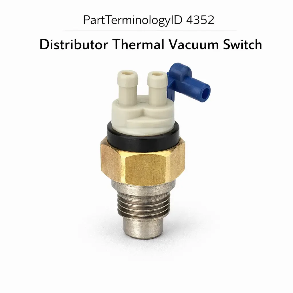
Two-Port versus Three-Port Switch Configurations
The two-port distributor thermal vacuum switch has one vacuum inlet port connected to either ported vacuum (vacuum present only above idle throttle position, absent at idle) or manifold vacuum (vacuum present at all throttle positions including idle), and one outlet port connected to the distributor vacuum advance canister. The switch gates the vacuum supply to the distributor based on coolant temperature, blocking or passing it at the calibrated threshold.
The three-port switch adds a second vacuum inlet port, allowing the switch to select between two vacuum sources at the threshold temperature. A common three-port configuration supplies ported vacuum to the distributor during cold operation (below the threshold) and switches to manifold vacuum above the threshold, or blocks all vacuum during cold operation and supplies ported vacuum only after warm-up. The three-port configuration changes not just the presence or absence of advance but the type of advance characteristic (load-dependent versus speed-dependent) as the engine crosses the threshold temperature.
A two-port replacement in a three-port application leaves one vacuum inlet permanently unconnected, eliminating the vacuum source switching function and reducing the distributor advance to a simple gated circuit rather than the original dual-source strategy. The port count must be confirmed as a mandatory attribute.
Thread Specification and Sealing Method
The switch threads into a coolant passage port in the intake manifold or thermostat housing and is in contact with coolant at operating pressure and temperature. The thread specification (diameter, pitch, and thread form) and the sealing method (crush washer for straight threads, thread sealant for NPT tapered threads) follow the same requirements described for PartTerminologyID 4272 and PartTerminologyID 4308. A tapered pipe thread switch in a straight thread port will not seal against coolant pressure. A straight thread switch installed without the required crush washer will weep coolant at the thread shoulder on the first heat cycle.
Top Return Scenarios
Scenario 1: "Cold-pass switch in cold-block circuit, pinging during cold start, retarded timing at operating temperature"
The replacement is a cold-pass type. The original was cold-block. During cold start the distributor canister receives vacuum advance, causing pinging on a cold morning. At operating temperature the switch blocks vacuum, retarding timing from the original warm calibration and reducing fuel economy.
Prevention language: "Vacuum routing direction: [cold-block, vacuum passes above threshold / cold-pass, vacuum passes below threshold]. Verify routing direction against the original switch. A cold-pass switch in a cold-block application advances ignition timing during cold start (causing pinging) and retards it at operating temperature (reducing fuel economy)."
Scenario 2: "Two-port switch in three-port application, vacuum source switching function eliminated"
The original switch selects between ported and manifold vacuum at the threshold. The replacement has two ports and connects only one vacuum source to the distributor at all temperatures above the threshold. The dual-source advance strategy is replaced by a single-source strategy, altering the distributor advance curve under load conditions where the original system switched to manifold vacuum.
Prevention language: "Port count: [two-port / three-port]. Verify the port count against the original switch. A two-port replacement in a three-port application eliminates the vacuum source switching function. The distributor advance characteristic changes from the dual-source strategy to a single-source strategy across all operating conditions above the threshold."
Scenario 3: "Thread mismatch, coolant weep at intake manifold switch port"
The replacement uses M12 x 1.5 metric straight thread. The intake manifold port uses 3/8-18 NPT tapered thread. The straight thread switch does not seal through thread interference and weeps coolant at the switch base under operating pressure after the first heat cycle.
Prevention language: "Thread specification: [diameter x pitch, thread form: NPT tapered / metric straight with crush washer]. Verify thread form against the intake manifold or thermostat housing port before installation. A straight thread switch will not seal in an NPT tapered port at any torque."
Core Listing Attributes for PartTerminologyID 4352
PartTerminologyID: 4352
Component: Distributor Thermal Vacuum Switch
Temperature threshold in degrees Celsius (mandatory, in title)
Vacuum routing direction: cold-block or cold-pass (mandatory, in title)
Port count: two-port or three-port with vacuum source identification for each port (mandatory)
Thread specification: diameter, pitch, and thread form (mandatory)
Sealing method: crush washer, O-ring, or NPT thread sealant (mandatory)
Vacuum source compatibility: ported vacuum, manifold vacuum, or selectable (mandatory)
Year/make/model/engine
FAQ (Buyer Language)
How do I distinguish a distributor thermal vacuum switch from an EGR vacuum control switch?
Both are threaded coolant passage switches that gate vacuum at a temperature threshold and appear physically identical. The distributor switch is connected by a vacuum hose to the distributor vacuum advance canister. The EGR switch connects to the EGR valve vacuum port or EGR solenoid. Trace the vacuum hose from the switch to its destination before ordering a replacement to confirm which circuit the switch controls.
Can I test the original switch before replacing it?
Yes. Remove the switch and place the sensing tip in heated water while monitoring temperature with a calibrated thermometer. Apply a vacuum gauge to the outlet port and a vacuum source to the inlet port. The switch should change its vacuum routing state within a few degrees of the rated threshold. A switch that does not change state at the rated threshold or that leaks vacuum through the blocked port requires replacement.
Related PartTerminologyIDs
Engine Coolant Temperature Vacuum Control Switch (PartTerminologyID 4308): controls vacuum routing to EGR, thermostatic air cleaner, and other emissions circuits; same physical form and installation method as the distributor thermal vacuum switch but connected to different vacuum circuits; confirm the switch's vacuum hose destination before ordering either component
Distributor Vacuum Advance Unit (if cataloged): the canister that receives gated vacuum from the switch; a functioning switch with no advance response indicates a failed or disconnected advance canister; test the canister by applying direct vacuum before attributing a no-advance complaint to the switch
Status in New Databases
PIES/PCdb: PartTerminologyID 4352, Distributor Thermal Vacuum Switch
PIES 8.0 / PCdb 2.0: No change in PartTerminologyID or terminology label
Final Take for PartTerminologyID 4352
Distributor Thermal Vacuum Switch (PartTerminologyID 4352) is the ignition advance control PartTerminologyID where vacuum routing direction and temperature threshold together determine whether the engine pings on cold mornings and achieves designed fuel economy at cruise. State the routing direction in the title. State the threshold in the title. State the port count with vacuum source identification. State the thread specification with thread form and sealing method. For PartTerminologyID 4352, vacuum routing direction, port count, and thread form are the three attributes that prevent the three most common return scenarios in the distributor thermal vacuum switch buyer population.