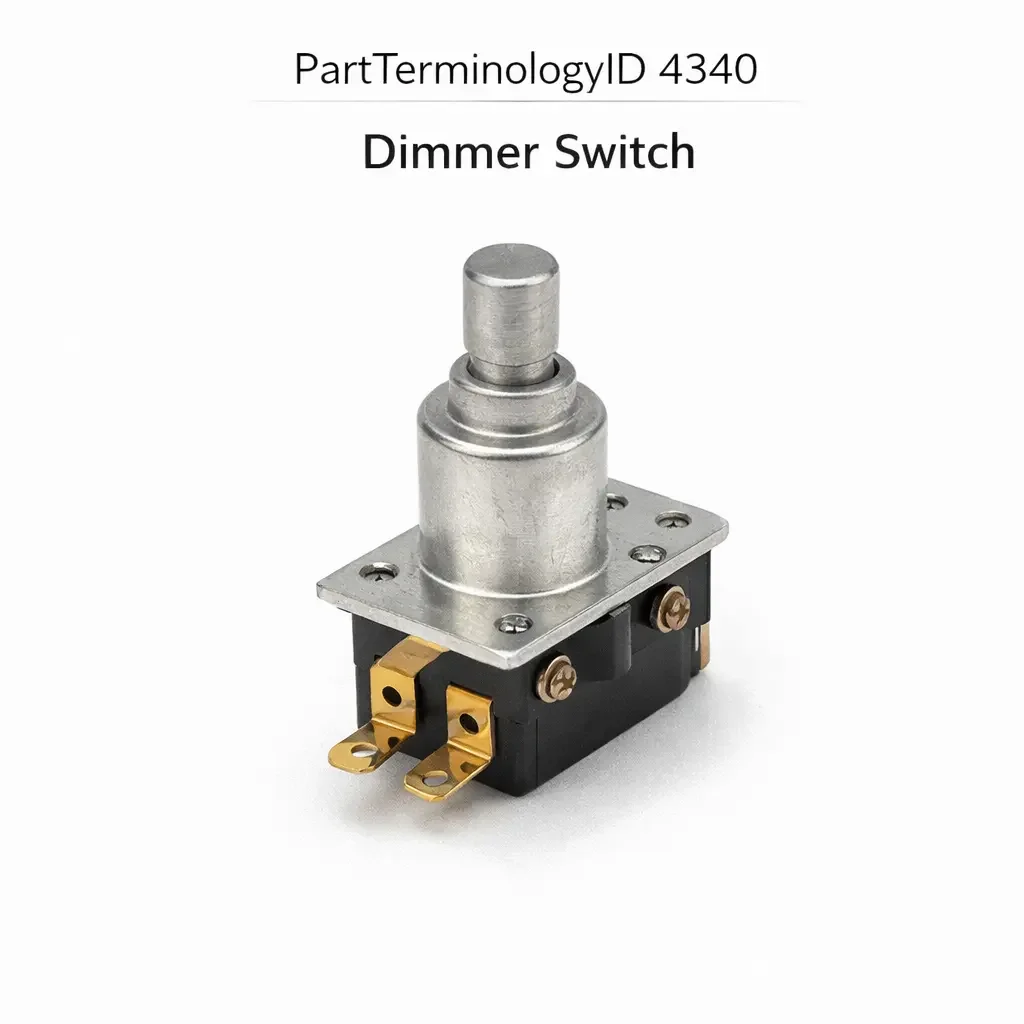
Dimmer Switch (PartTerminologyID 4340): Control Architecture Type, Load Compatibility, and Instrument Panel Integration
Written by Arthur Simitian | PartsAdvisory
PartTerminologyID 4340, Dimmer Switch, is the driver-operated control device that regulates the brightness of the instrument panel illumination, interior accent lighting, and in some applications the courtesy lighting circuit, by varying the voltage or current delivered to the lighting load through a resistive, electronic, or pulse-width-modulated output stage, and in modern vehicles by sending a digital dimming command to the body control module or lighting control module that adjusts the module's PWM output to the lighting circuits. That definition covers the brightness regulation function correctly and leaves unresolved every question that determines whether the replacement switch's output type (resistive, electronic PWM, or digital command) matches the original lighting circuit's dimming method, whether the switch's load rating covers the total current draw of all lighting circuits controlled simultaneously through the switch, whether the switch connector pin count and terminal assignment match the harness at the instrument panel or steering column position, whether the switch is a rotary type with a stepped or continuous travel range or a sliding type or a rocker type or a touch-sensitive capacitive type depending on the instrument panel design, whether the switch includes an integrated dome light on or off position at the end of the travel range in addition to the instrument brightness range, whether the replacement is compatible with LED instrument backlighting that requires a PWM dimmer signal rather than a resistive voltage reduction, whether the switch includes a headlamp flash-to-pass function or a headlamp pull-to-activate function integrated into the same stalk or switch body, and whether the switch is a standalone instrument dimmer or an integrated multifunction stalk that combines the dimmer function with turn signals, high beam activation, wiper control, or cruise control inputs.
It does not specify the output type, load rating, connector pin count, switch type, dome light position, LED PWM compatibility, integrated functions, or multifunction stalk configuration. A listing under PartTerminologyID 4340 that states only year, make, and model without output type and load rating cannot be evaluated by a technician replacing a failed instrument dimmer switch on a vehicle where the original switch used a pulse-width-modulated electronic output to drive the LED instrument backlight circuit at 12 volts with a variable duty cycle, and the replacement is a resistive rheostat type that reduces voltage to the backlight circuit by inserting a variable resistance in series, which will cause the LED backlight driver circuits to flicker or operate incorrectly because LED backlight systems are designed for PWM dimming and not for resistive voltage reduction that pushes the LED driver below its minimum input voltage threshold at lower brightness settings.
For sellers, PartTerminologyID 4340 is the interior lighting control PartTerminologyID with the widest variation in control architecture across vehicle generations, because resistive rheostat dimming was the universal approach through the early 1990s, electronic PWM dimming became standard through the 2000s, and digital bus command dimming has become dominant on vehicles with CAN bus or LIN bus body electronics. A replacement that matches the year, make, and model but uses the wrong control architecture for the specific instrument panel lighting generation will produce a dimmer that appears to function at installation (the instrument lights will change brightness) but will either flicker the LED backlights at specific brightness settings, fail to achieve the lowest brightness setting on a PWM-controlled circuit, or produce no dimming effect at all on a digital bus command circuit where the switch must transmit a recognized network message rather than an analog output.
What the Dimmer Switch Does
Resistive Rheostat Architecture and the Direct Voltage Reduction Approach
The resistive rheostat dimmer switch is the oldest and simplest dimming architecture, used on vehicles through the early 1990s and still present on some commercial and specialty vehicle applications. In this architecture, the switch contains a variable resistor (rheostat) whose resistance changes continuously or in steps as the driver rotates or slides the switch. The rheostat is wired in series between the lighting circuit supply and the instrument panel lamps, and the variable resistance reduces the voltage across the lamps as the resistance increases, reducing lamp brightness proportionally.
The resistive architecture carries the full lamp circuit current through the switch's rheostat element. A typical instrument panel lighting circuit drawing 3 to 8 amperes passes entirely through the switch, and the power dissipated by the rheostat at intermediate brightness settings generates heat within the switch body. A rheostat rated for 5 amperes maximum installed in a circuit drawing 7 amperes will overheat at intermediate brightness settings, causing the rheostat element to degrade progressively and eventually produce an open circuit. The load rating must match or exceed the total current draw of all lighting circuits routed through the switch.
The resistive architecture is not compatible with LED instrument backlight circuits because LEDs and their driver circuits are constant-current devices that do not respond predictably to a reduced supply voltage. When the supply voltage is reduced below the LED driver's minimum input threshold, the driver loses regulation and the LED output drops non-linearly or flickers. LED backlight circuits require PWM dimming, where the supply voltage remains at full battery voltage and the driver is switched on and off at a frequency above the threshold of human flicker perception, with the ratio of on-time to off-time (duty cycle) determining the perceived brightness.
Electronic PWM Dimmer Architecture and the LED Backlight Requirement
The electronic PWM dimmer switch uses an internal electronic circuit (typically a MOSFET switching stage) to generate a pulse-width-modulated output at a fixed frequency (typically 200 to 2000 Hz) with a variable duty cycle controlled by the driver's rotary or slide input. The LED backlight driver circuits in the instrument cluster and other panel illumination modules receive the PWM signal and modulate their output to the LED elements proportionally, providing smooth, flicker-free brightness reduction from full brightness to near-off without inserting resistance in the LED driver's supply path.
A PWM dimmer switch must produce a PWM frequency within the range accepted by the specific instrument cluster's backlight driver. A switch producing PWM at 200 Hz in a cluster whose backlight driver operates correctly only at 500 Hz or above will produce visible flicker at low brightness settings because the 200 Hz switching frequency is within the range where some individuals can perceive the individual on and off cycles as flicker rather than continuous illumination. The frequency specification must be confirmed against the instrument cluster's backlight driver specification for applications where the PWM frequency range is defined in the service manual.
The PWM dimmer switch carries much lower current than a resistive dimmer because the LED backlight driver circuit draws only the low-level PWM signal current through the switch, with the actual LED drive current sourced from the LED driver's own power supply. This means the PWM dimmer switch's contact or output stage current rating is not the primary specification concern; the PWM frequency and duty cycle range are the governing specifications.
Digital Bus Command Architecture and the Module Input Requirement
On vehicles with LIN bus or CAN bus body electronics managing the interior lighting, the dimmer switch generates a digital brightness command transmitted on the vehicle network rather than a physical analog output. The lighting control module or BCM receives the command and adjusts its PWM output to the lighting circuits to the commanded level. The switch in this architecture contains a small microcontroller or encoder that translates the driver's rotary or touch input into a digital message with the appropriate brightness level identifier.
A digital bus command dimmer switch must transmit messages that the receiving module recognizes as valid dimmer commands with the correct message identifiers for the specific vehicle's network protocol. A switch transmitting generic or incorrect message identifiers will not produce any dimming response from the lighting control module, because the module ignores messages it does not recognize. In some cases the module may also generate a diagnostic fault code for a missing or unexpected bus message on the dimmer channel.
Post-installation programming may be required for digital bus command dimmer switches on some applications, where the module must learn the switch's network address before accepting its messages. The listing must disclose the programming requirement for all digital bus command switches, following the same convention established for cruise control and other bus-command input devices.
Integrated Dome Light Position and the End-of-Travel Function
Many instrument dimmer switches include a dedicated dome light on or off position integrated at one end of the dimmer's travel range, most commonly at the fully clockwise or fully forward position for rotary and slide switches respectively. Rotating or sliding the switch past the minimum instrument brightness position activates the dome light circuit directly, providing an override that illuminates the dome light without requiring the driver to find a separate dome light switch.
A replacement dimmer switch without the integrated dome light position in an application that includes it removes the dome light override function from the driver's instrument panel control set. On vehicles where the dome light switch is only accessible through the instrument dimmer's end position, the driver loses the ability to activate the dome light from the instrument panel entirely. The dome light override function and the end-of-travel contact configuration must be confirmed as present or absent in the replacement before ordering.
Multifunction Stalk Integration and the Combined Switch Replacement Requirement
On many vehicles, the instrument dimmer function is integrated into a multifunction stalk on the steering column alongside the headlamp activation, flash-to-pass, high beam toggle, and in some configurations the turn signal. The dimmer in this configuration is not a standalone switch but a rotary ring or rocker segment on the stalk body. Replacing the dimmer function requires replacing the entire multifunction stalk, not an individual switch element.
A listing that covers a multifunction stalk under PartTerminologyID 4340 must state all integrated functions in the stalk and must confirm that the complete stalk is the replacement unit, not merely the dimmer segment. A buyer who orders expecting a standalone dimmer switch and receives a full multifunction stalk will be surprised by the scope of replacement but will not be served by a dimmer-only part that does not exist for the application. The listing must make the multifunction stalk requirement explicit so the buyer understands the replacement scope before ordering.
Headlamp Circuit Integration and the Rotary Switch Headlamp Position
Some rotary instrument dimmer switches include headlamp activation positions in addition to the instrument brightness range, where the driver rotates the switch knob from the off position through parking lights to headlights before reaching the instrument brightness adjustment range. In this configuration, the switch controls both the headlamp relay circuit and the instrument dimmer output from a single rotary switch body.
A replacement for a headlamp-integrated dimmer switch must cover both the headlamp switching function and the instrument dimming function. A replacement covering only the instrument dimming range without the headlamp positions will leave the headlamp circuit uncontrolled at the switch position. On vehicles where the headlamp switch and instrument dimmer are combined in a single knob, the headlamp switching contacts, the headlamp circuit current rating, and the dimmer output type must all be confirmed in the replacement specification.
Load Compatibility, LED Circuit Interaction, and Why the Wrong Dimmer Damages the Instrument Cluster
Why resistive dimming damages LED backlight driver circuits
When a resistive rheostat dimmer is connected in series with an LED backlight driver circuit, the voltage at the driver's input terminal drops as the rheostat resistance increases. LED backlight driver ICs typically require a minimum input voltage of 8 to 10 volts to maintain internal regulation. As the resistive dimmer is adjusted to lower brightness settings, the input voltage approaches and eventually crosses this minimum threshold, causing the driver IC to exit its regulated operating range.
Below the minimum input voltage, the driver IC's behavior is undefined by the manufacturer: some drivers will flicker the LED output at a frequency proportional to the degree of undervoltage, others will cycle the output on and off at a low frequency as the internal capacitance charges and discharges, and others will produce a brief bright flash before entering a protection shutdown. All three behaviors are non-functional and potentially damaging to the driver IC's internal switching transistors if sustained. The correct dimmer for an LED backlight circuit is a PWM type that maintains full input voltage to the driver IC at all brightness settings.
PWM frequency mismatch and visible flicker in the instrument cluster
An LED backlight circuit driven by a PWM signal at too low a frequency will produce visible flicker that some drivers perceive as eye strain or fatigue during extended night driving. The threshold below which flicker becomes perceptible varies by individual (typically 80 to 120 Hz for most observers, lower for some) but PWM frequencies below 200 Hz are generally considered borderline for instrument cluster backlighting where the driver's eyes are repeatedly scanning the display.
A replacement PWM dimmer switch producing a 100 Hz signal in a cluster whose backlight driver was designed for a 500 Hz signal will produce perceptible flicker at intermediate brightness settings on every night drive. The buyer will attribute the flicker to a failing instrument cluster rather than a PWM frequency mismatch in the dimmer switch. The PWM frequency must be stated in the listing for every PWM output dimmer switch.
Digital command switches and the unresponsive instrument cluster symptom
A digital bus command dimmer switch that transmits incorrect message identifiers produces an instrument cluster that does not respond to any dimmer input. The cluster's backlight remains at its default brightness regardless of switch position because the lighting control module or BCM does not recognize the switch's messages as valid dimmer commands. This symptom is identical to a failed dimmer switch from the driver's perspective but is caused by a protocol mismatch rather than a component failure.
The unresponsive cluster from a protocol mismatch is a difficult diagnosis because the switch and the cluster are both functioning correctly within their respective specifications. The diagnostic path requires confirming the switch's output message identifiers against the vehicle network's protocol specification, which is not accessible without a factory-level scan tool or the vehicle network message database. Preventing this scenario through correct listing specification (stating the protocol and confirming OEM-specific versus generic protocol compatibility) is more effective than addressing it through post-purchase diagnosis.
Why This Part Generates Returns
Buyers return dimmer switches because the replacement is a resistive rheostat type and the instrument cluster uses LED backlighting that requires PWM dimming, producing flicker at low brightness settings and driver circuit damage after sustained use; the PWM frequency is 100 Hz and the cluster backlight driver requires 500 Hz minimum, producing perceptible flicker on every night drive; the switch is a standalone dimmer and the application requires a multifunction stalk that integrates turn signals, high beam, and dimmer, requiring the buyer to replace the entire stalk rather than just the dimmer element; the replacement does not include the integrated dome light end-of-travel position present in the original, removing the driver's only dome light override control; the digital bus command switch transmits a generic protocol message and the lighting control module does not recognize it as a valid dimmer command, leaving the cluster at fixed default brightness; the load rating is 3 amperes and the combined instrument panel lighting circuit draws 6.5 amperes through a resistive dimmer circuit, causing the rheostat element to overheat and open after 30 minutes of operation at intermediate brightness; the connector is a three-pin type and the harness at the instrument panel position has four pins because the original switch included a separate park lamp position output that the replacement omits; and the replacement dimmer knob spline profile is an eight-tooth spline and the original was a six-tooth spline, preventing the original knob from being transferred and leaving the switch without a knob after installation.
Top Return Scenarios
Scenario 1: "Resistive rheostat in LED backlight circuit, driver IC undervoltage, flicker and eventual driver failure"
The buyer installs the replacement resistive rheostat dimmer in a vehicle with an LED instrument cluster. At full brightness the cluster illuminates normally. As the dimmer is reduced to 30 percent brightness, the cluster begins to flicker intermittently. At 20 percent brightness the cluster flickers continuously. The LED backlight driver IC is receiving 8.2 volts at this rheostat setting, which is below its 9-volt minimum regulated input threshold. After two weeks of use primarily at low brightness settings, the backlight driver IC overheats from sustained operation in its unregulated region and fails permanently, requiring instrument cluster replacement.
Prevention language: "Output type: [resistive rheostat / electronic PWM, specify frequency / digital bus command, specify protocol]. This switch produces a [output type] output. LED instrument backlight circuits require PWM dimming. A resistive rheostat dimmer reduces the input voltage to the LED backlight driver circuit below its minimum operating threshold at low brightness settings, causing flicker and potential driver IC failure. Verify the instrument backlighting type before ordering."
Scenario 2: "PWM frequency 100 Hz, cluster backlight driver requires 500 Hz minimum, perceptible flicker on every night drive"
The buyer installs the replacement PWM dimmer. At full brightness the cluster is normal. At intermediate and low brightness settings a subtle but persistent flicker is visible in the instrument cluster, particularly noticeable in peripheral vision during extended highway night driving. The replacement switch produces a 100 Hz PWM signal. The cluster backlight driver was designed for a 500 Hz or higher input to remain above the human flicker perception threshold.
Prevention language: "PWM output frequency: [X] Hz. Verify the PWM frequency against the instrument cluster backlight driver's minimum frequency specification. A PWM frequency below 200 Hz may produce perceptible flicker at intermediate and low brightness settings in LED backlight circuits designed for higher frequency inputs."
Scenario 3: "Standalone dimmer ordered for multifunction stalk application, stalk replacement required"
The buyer's instrument dimmer function has failed on a steering column stalk that integrates turn signals, high beam, and dimmer in a single assembly. The listing covers the vehicle under the dimmer switch PartTerminologyID without noting the multifunction stalk requirement. The buyer orders a standalone rotary dimmer switch. The standalone unit has no provision for installation at the steering column stalk position. The turn signal and high beam functions in the original stalk are functional; only the dimmer element has failed. The entire stalk must be replaced to restore the dimmer function.
Prevention language: "Replacement configuration: [standalone dimmer switch / multifunction stalk including [list integrated functions]]. This application requires the complete multifunction stalk assembly. The dimmer function is integrated into the stalk and cannot be replaced independently. All stalk functions are covered by this replacement."
Scenario 4: "Dome light end-of-travel position absent in replacement, driver loses panel dome light override"
The buyer's original rotary dimmer switch includes a click-stop position at maximum counterclockwise rotation that activates the dome light circuit. The replacement switch covers the instrument brightness range but does not include the dome light click-stop position. After installation, the dome light cannot be activated from the instrument panel. The dome light is accessible only through the overhead console switch, which requires the driver to reach upward to activate it rather than using the instrument panel control.
Prevention language: "Dome light override position: [included at end of travel / not included]. Verify whether the original switch includes an end-of-travel dome light position. A replacement without this position removes the dome light panel override function. On vehicles where the instrument dimmer is the only accessible dome light control on the instrument panel, this function loss may require a separate dome light switch installation."
Scenario 5: "Digital bus switch transmits generic protocol, lighting module unresponsive, cluster at fixed default brightness"
The buyer installs the replacement digital dimmer switch. No dimming effect is produced at any switch position. The instrument cluster illuminates at a fixed mid-level brightness regardless of the switch position. The lighting control module does not respond to the switch's output because the replacement transmits generic LIN bus dimmer messages that do not match the vehicle-specific message identifiers the module is programmed to accept.
Prevention language: "Protocol compatibility: [OEM-specific protocol for [make/model/year range] / generic protocol, not compatible with OEM lighting control modules]. This switch [is / is not] OEM-protocol compatible. A switch transmitting generic bus messages will not be recognized by the vehicle-specific lighting control module. The instrument cluster will remain at default brightness regardless of switch position."
Scenario 6: "Load rating 3 amperes, combined panel circuit draws 6.5 amperes, rheostat overheats and opens at 30 minutes"
The buyer installs the replacement resistive rheostat switch. At full brightness and at minimum brightness the rheostat element carries minimal power dissipation. At intermediate brightness settings (40 to 70 percent) the rheostat dissipates the highest power (product of current and voltage drop across the rheostat). The combined instrument panel, HVAC panel, and switch illumination circuit draws 6.5 amperes. The replacement rheostat is rated for 3 amperes maximum. After 30 minutes of operation at 50 percent brightness, the rheostat element reaches thermal failure temperature and opens, leaving the instrument panel at maximum brightness with no dimmer control.
Prevention language: "Load rating: [X] amperes maximum. Verify the total current draw of all lighting circuits routed through the dimmer before ordering. Sum the current draw of all instrument panel, HVAC panel, switch illumination, and accent lighting circuits connected to the dimmer output. A rheostat installed in a circuit exceeding its load rating will overheat at intermediate brightness settings and fail by open circuit."
Scenario 7: "Four-pin harness, three-pin replacement, park lamp output unconnected, parking lights non-functional through switch"
The buyer's original dimmer switch includes a park lamp activation position that routes battery voltage to the parking lamp relay through the switch's fourth pin. The replacement covers only the instrument brightness range with a three-pin connector. After installation, the dimmer functions correctly for instrument brightness. The first night the driver attempts to use parking lights, the park lamp relay receives no signal from the fourth switch pin. The parking lights do not activate through the switch.
Prevention language: "Connector pin count: [X] pins covering [instrument dimmer output, dome light output, park lamp output, ground, supply as applicable]. Verify pin count and function assignment against the original switch. A replacement with fewer pins than the original leaves active circuit outputs unconnected. Park lamp and dome light outputs are commonly integrated into the dimmer switch connector on applications where the dimmer also serves as the headlamp/park lamp rotary switch."
Scenario 8: "Eight-tooth spline on replacement shaft, original knob is six-tooth, knob cannot be transferred, switch inoperable without knob"
The buyer replaces the dimmer switch body. The original knob is retained for transfer to the new switch. The replacement switch shaft has an eight-tooth spline. The original knob has a six-tooth bore. The knob cannot be seated on the replacement shaft. The replacement knob for the eight-tooth shaft is not available from the same supplier. The buyer cannot operate the replacement switch without a knob and the original switch body had a permanently attached knob that is now separated from the failed switch body.
Prevention language: "Knob interface: [X]-tooth spline shaft. Knob: [included / not included, transfer original knob]. Verify the knob spline tooth count before ordering if the original knob is to be transferred. A spline count mismatch prevents knob transfer and leaves the switch inoperable. Confirm knob inclusion or availability as a separate item if the original knob is not transferable."
Core Listing Attributes for PartTerminologyID 4340
PartTerminologyID: 4340
Component: Dimmer Switch
Output type: resistive rheostat, electronic PWM with frequency in Hz, or digital bus command with protocol (mandatory, in title)
Load rating in amperes for resistive and PWM types (mandatory)
PWM frequency in Hz for PWM output types (mandatory)
Protocol and OEM compatibility for digital bus command types (mandatory)
Switch type: rotary, slide, rocker, or touch-sensitive capacitive (mandatory)
Integrated functions: dimmer only, dimmer with dome light position, dimmer with park lamp position, or multifunction stalk (mandatory, in title for multifunction)
Dome light end-of-travel position: present or absent (mandatory)
Connector pin count and terminal assignment with function mapping (mandatory)
Post-installation programming requirement for digital bus types (mandatory)
Knob interface: spline tooth count and knob inclusion status (mandatory for rotary types)
Instrument lighting compatibility: incandescent, LED with PWM requirement, or both (mandatory)
Dimmer range: minimum and maximum output percentage or voltage (recommended)
Year/make/model/submodel/trim
Note for instrument cluster generations where backlighting changed from incandescent to LED within a model year range
Note for multifunction stalk applications where dimmer function cannot be replaced independently
Note for headlamp-integrated rotary switch applications requiring full headlamp circuit coverage
Catalog Checklist for ACES/PIES Teams
PartTerminologyID = 4340
Require output type in title: resistive rheostat, PWM, or digital bus command (mandatory)
Require load rating for resistive and PWM types (mandatory)
Require PWM frequency for PWM output types (mandatory)
Require protocol and OEM compatibility for digital bus command types (mandatory)
Require integrated function content in title for multifunction stalk applications (mandatory)
Require dome light end-of-travel position: present or absent (mandatory)
Require connector pin count with function mapping (mandatory)
Require knob spline count and inclusion status for rotary types (mandatory)
Require post-installation programming disclosure for digital bus types (mandatory)
Prevent output type omission: a resistive rheostat in an LED backlight circuit causes driver IC undervoltage and potential cluster damage; output type must be in the title for every listing without exception
Prevent PWM frequency omission: a PWM frequency below 200 Hz produces perceptible flicker in LED backlight circuits; frequency must be stated for all PWM output switch listings
Prevent load rating omission: a rheostat installed in a circuit exceeding its load rating overheats and opens at intermediate brightness; load rating must be verified against combined circuit current draw
Prevent multifunction stalk omission: a buyer ordering a standalone dimmer for a multifunction stalk application receives an incompatible part; stalk configuration must be stated when the dimmer cannot be replaced independently
Prevent dome light position omission: a replacement without the dome light end-of-travel position removes the driver's panel-accessible dome light override; dome light position must be confirmed for all applications where it is present in the original
Prevent protocol omission: a digital bus command switch with a generic protocol will not be recognized by the vehicle-specific lighting module; protocol and OEM compatibility must be disclosed
Differentiate from Headlamp Switch (if cataloged separately): the headlamp switch controls the headlamp relay circuit; the dimmer switch controls instrument brightness; on vehicles where both functions are combined in a single rotary switch, the complete assembly is the replacement unit; confirm whether the application uses a combined or separate headlamp and dimmer switch before ordering
Differentiate from Interior Light Switch (PartTerminologyID or similar): the interior light switch controls dome light and reading light activation independent of the dimmer; the dimmer switch controls brightness of the instrument panel illumination; both may be on the same instrument panel but serve different circuit functions
FAQ (Buyer Language)
How do I know if my instrument cluster uses incandescent or LED backlighting?
The simplest field test is to turn on the headlamps and observe the instrument cluster at night. LED backlighting produces crisp, even, white or colored illumination with no warm-up period. Incandescent backlighting produces slightly warmer light and is visible as small individual light points in some clusters. Any vehicle produced after 2008 with a digital instrument cluster or a multi-information display almost certainly uses LED backlighting. Confirm in the service manual under the instrument cluster specification section if uncertain.
Can I use a PWM dimmer to replace a resistive rheostat dimmer on my older vehicle?
Yes, provided the PWM dimmer's connector and mounting specification match the original switch position. Upgrading from resistive to PWM dimming is beneficial on vehicles that have had their instrument lighting converted to LED bulbs, as the PWM output is compatible with LED backlight drivers while the resistive output is not. Confirm that the PWM dimmer's connector pin count and output voltage range match the instrument lighting circuit's requirements before ordering.
My instrument brightness does not change when I rotate the dimmer. Is the switch failed?
A dimmer that produces no brightness change when rotated may indicate a failed switch output stage, a disconnected switch connector, or a failed lighting control module output on digital bus command systems. On a digital bus command system, connect a scan tool and monitor the BCM or lighting module's dimmer input parameter while rotating the switch. If the module detects the switch input but the cluster brightness does not change, the module output stage has failed. If the module does not detect any switch input, the switch is the failed component.
Why does my instrument panel flicker at low brightness settings after replacing the dimmer?
Flicker at low brightness settings is the characteristic symptom of a PWM frequency mismatch or a resistive dimmer installed on an LED backlight circuit. On a PWM dimmer, the flicker indicates the PWM frequency is too low for the backlight driver's specified input frequency range. On a resistive dimmer, the flicker indicates the LED backlight driver's input voltage has dropped below its minimum regulated threshold. Identify the dimmer output type first, then confirm the frequency or the input voltage at the lowest brightness setting.
My vehicle's dimmer is part of the turn signal stalk. Can I replace just the dimmer element?
On most steering column multifunction stalks, the dimmer ring or segment is not a serviceable component separate from the stalk body. The stalk must be replaced as a complete assembly. Confirm whether a standalone dimmer replacement is available for the specific application before ordering. If the stalk must be replaced, confirm that all integrated functions in the replacement stalk (turn signals, high beam, flash-to-pass, wiper in some applications) match the original stalk's function set.
Does the dimmer switch need programming after installation?
On resistive and PWM output dimmer switches, no programming is required. On digital bus command switches, programming may be required depending on the vehicle's network architecture. If the listing does not specify the programming requirement, assume it may be required on any post-2010 vehicle with a LIN bus or CAN bus interior lighting architecture and confirm with the supplier before purchase.
Related PartTerminologyIDs
Headlamp Switch (if cataloged separately): the switch controlling the headlamp relay circuit; on vehicles where the headlamp and instrument dimmer are combined in a single rotary switch assembly, the complete assembly is the replacement unit for either function failure; confirm the combined versus separate configuration before ordering either component
Instrument Cluster (if cataloged): the display assembly containing the LED backlight drivers; a cluster with a damaged backlight driver from sustained operation with a resistive dimmer below the driver's minimum input voltage will require cluster replacement independent of the dimmer switch replacement; confirm cluster backlight driver function before concluding the new dimmer is also failed
Body Control Module (if cataloged): the module managing interior lighting PWM outputs on BCM-integrated systems; a BCM that does not respond to the digital dimmer switch input may have a failed dimmer input channel; confirm BCM input function with a scan tool before replacing the switch a second time
Multifunction Switch (PartTerminologyID or similar): the complete steering column stalk assembly that may integrate the dimmer with turn signal, high beam, and wiper functions; when the dimmer function cannot be replaced independently, the multifunction switch is the correct replacement PartTerminologyID
Status in New Databases
PIES/PCdb: PartTerminologyID 4340, Dimmer Switch
PIES 8.0 / PCdb 2.0: No change in PartTerminologyID or terminology label
Final Take for PartTerminologyID 4340
Dimmer Switch (PartTerminologyID 4340) is the interior lighting control PartTerminologyID where the output type is the attribute with the highest consequence of mismatch, because a resistive rheostat delivered for an LED backlight circuit does not merely produce incorrect dimming behavior but actively damages the instrument cluster's backlight driver IC through sustained undervoltage operation at low brightness settings, converting a switch replacement into a cluster replacement. The PWM frequency is the second most consequential attribute, because a frequency below the backlight driver's specified minimum produces perceptible flicker on every night drive. The multifunction stalk configuration is the third, because a buyer ordering a standalone dimmer for a stalk application receives a part that has no viable installation path and must be returned before the correct stalk assembly is ordered.
State the output type in the title. State the PWM frequency for PWM types. State the load rating for resistive and PWM types. State the integrated function content in the title for multifunction stalk applications. State the dome light end-of-travel position. State the connector pin count with function mapping. State the knob spline count and inclusion status. State the protocol and programming requirement for digital bus types. For PartTerminologyID 4340, output type, PWM frequency, and multifunction stalk configuration are the three attributes that prevent the three most consequential and least recoverable return scenarios in the dimmer switch buyer population.