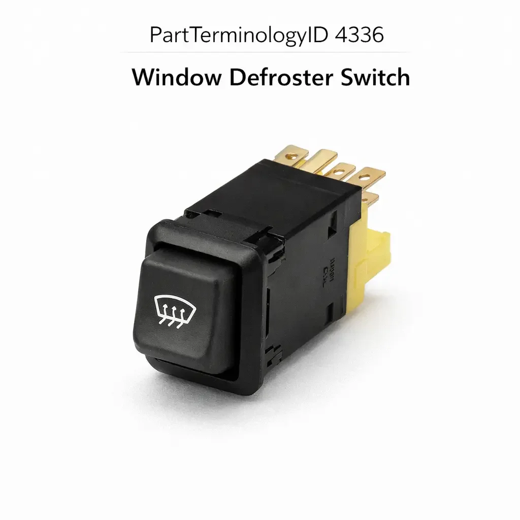
Window Defroster Switch (PartTerminologyID 4336): Timer Circuit Compatibility, Indicator Lamp Integration, and Body Control Module Signal Architecture
Written by Arthur Simitian | PartsAdvisory
PartTerminologyID 4336, Window Defroster Switch, is the driver-operated switch that activates the rear window defroster grid circuit and in many applications the heated exterior mirror circuits, energizing a relay or a body control module output that delivers battery voltage to the resistive heating grid embedded in the rear glass and to the mirror heating elements, and in most applications incorporating an automatic timed shutoff function that deactivates the defroster circuit after a fixed interval (typically 10 to 20 minutes) to protect the defroster grid from overheating and to prevent excessive electrical load on the alternator during extended idling. That definition covers the defroster activation and timed shutoff function correctly and leaves unresolved every question that determines whether the replacement switch is compatible with the vehicle's defroster timer circuit architecture, whether the switch includes an integrated timer circuit or relies on an external timer module, whether the switch's indicator lamp or LED illumination method and voltage match the defroster circuit's feedback signal, whether the connector pin count and terminal assignment match the harness at the instrument panel or HVAC panel mounting position, whether the switch is a momentary push-button type that activates on press and deactivates at timer expiry or a latching toggle type that holds the active state until pressed again, whether the switch is compatible with the body control module's defroster input on vehicles where the BCM governs the defroster relay and timer function rather than a standalone timer circuit, whether the replacement covers rear window defroster only or both rear window and heated mirror circuits through a combined output, and whether the switch illumination brightens with the instrument panel dimmer circuit or operates at fixed brightness independent of the dimmer setting.
It does not specify the timer circuit architecture, timer interval, indicator lamp method, connector pin count, switch actuation type, BCM compatibility, circuit coverage, or dimmer integration. A listing under PartTerminologyID 4336 that states only year, make, and model without timer circuit architecture and switch actuation type cannot be evaluated by a technician replacing a failed rear defroster switch on a vehicle where the original switch is a momentary push-button that sends a single activation pulse to an external timer module, and the replacement is a latching toggle type that holds the defroster relay energized for as long as the switch is in the latched position, bypassing the timer function entirely and allowing the defroster grid to run continuously until the driver manually deactivates the switch, risking grid overheating and potential glass delamination on an extended drive in a warm climate where the driver forgets the defroster is active.
For sellers, PartTerminologyID 4336 is the body electrical PartTerminologyID where the timer circuit architecture and the switch actuation type together determine whether the defroster's overtemperature protection function is preserved after replacement. A latching switch in a momentary-switch application is not merely a functional inconvenience that requires the driver to remember to turn off the defroster manually. It is the removal of an engineering protection feature that prevents grid damage and glass delamination. This consequence places the timer architecture attribute in the same importance tier as the contact configuration attribute in brake and safety switch PartTerminologyIDs, because the outcome of the mismatch is not an incorrect function but the absence of a damage prevention function.
What the Window Defroster Switch Does
Defroster Grid Circuit and the Relay Activation Function
The rear window defroster grid is a network of resistive silver-ceramic conductors applied to the interior surface of the rear glass during manufacturing and connected to the vehicle electrical system through bus bars at each side of the glass. When energized, the grid draws 15 to 25 amperes from the battery through the defroster relay, generating sufficient heat to clear condensation, frost, and light ice accumulation from the rear glass within 3 to 10 minutes depending on ambient temperature and grid coverage density.
The defroster switch activates the relay coil circuit, which closes the relay's power contacts and delivers battery voltage to the grid. On direct relay circuits without a BCM, the switch either closes the relay coil circuit directly (for latching switch types) or sends a pulse to the timer module that holds the relay coil energized for the timed interval (for momentary switch types). On BCM-integrated circuits, the switch sends an activation signal to the BCM input, and the BCM activates the relay through a software-timed output.
The relay's power contacts carry the full 15 to 25 ampere grid current and must remain closed for the duration of the defroster cycle. The switch itself carries only the relay coil current (typically 0.1 to 0.3 amperes) on relay-based circuits, which is why defroster switch contact wear is rarely the primary failure mode. The more common failure modes are indicator lamp failure (the switch lights up but the grid is inactive due to a relay or circuit fault), timer module failure (the defroster activates but does not auto-shutoff), and switch body cracking from repeated pressing or from instrument panel flex during door closing.
Momentary versus Latching Switch Actuation Types
The momentary push-button switch produces a brief electrical pulse when pressed and returns to its unpressed state immediately. The defroster function is activated by this pulse, which triggers the timer circuit to hold the relay energized for the timed interval. The switch has no memory of its activation state and does not remain in an active physical position after pressing. The defroster's active status is indicated by the switch's integrated indicator lamp, which is powered from the defroster circuit or from the BCM's indicator output, not from a switch position contact.
The latching toggle switch physically locks in the pressed position when activated and remains in that position until pressed again to release. The relay coil circuit is completed while the switch is in the latched position and opens when the switch is released back to its unpressed state. A latching switch does not rely on a timer circuit for auto-shutoff: the driver must press the switch again to deactivate the defroster. On vehicles where the defroster system uses a latching switch, the timer function is either absent (the system relies entirely on the driver to deactivate) or is implemented in an external timer module that overrides the switch's latched contact by interrupting the relay coil circuit at timer expiry regardless of switch state.
Installing a momentary switch in a latching switch application produces a defroster that activates when the button is pressed and deactivates immediately when the button is released, because the momentary switch's pulse ends when the driver's finger leaves the button and the latching switch circuit relies on a sustained contact closure rather than a timer-held relay. The defroster will not function at all in this mismatch. Installing a latching switch in a momentary switch application produces a defroster that activates and remains permanently active until the driver presses the button again, because the latching switch provides a sustained contact closure that bypasses the timer pulse requirement. The auto-shutoff protection is absent.
Timer Circuit Architecture: Integrated versus External
The timed shutoff function in a rear defroster system is implemented in one of three locations: inside the switch body as an integrated RC or electronic timer circuit, in a dedicated external timer module mounted elsewhere in the vehicle, or in the BCM's software. Each location requires a different switch specification.
When the timer is integrated in the switch, the switch body contains both the mechanical actuation mechanism and the electronic timing circuit. The timer interval is fixed by the switch's internal components and cannot be adjusted externally. A replacement switch with an integrated timer must match the timer interval of the original: a replacement with a 10-minute integrated timer in an application that used a 20-minute integrated timer will deactivate the defroster earlier than expected, potentially not fully clearing the rear glass in cold ambient conditions. The timer interval must be stated for every switch with an integrated timer circuit.
When the timer is in an external module, the switch is a simple momentary contact device that sends a pulse to the module. The switch itself has no timer function and the replacement switch does not need to match any timer interval. However, the replacement must be a momentary type, not a latching type, because the external timer module is designed to receive a pulse and hold the relay itself. A latching switch sends a sustained contact closure rather than a pulse, which the timer module may interpret as a continuous activation command rather than a single trigger, potentially preventing the timer from starting its countdown and leaving the relay energized until the latching switch is released.
When the timer is in the BCM, the switch is a signal input device similar to the courtesy light switch in a BCM input architecture. The BCM receives the switch activation signal, starts its internal timer, and drives the defroster relay output for the timed interval. A replacement for a BCM-timed defroster switch must match the BCM's input signal type (switched ground or switched voltage) and must be a momentary type that sends a single activation event rather than a sustained state change.
Indicator Lamp Integration and the Active Status Feedback Function
The defroster switch indicator lamp illuminates while the defroster circuit is active, providing the driver with confirmation that the defroster is running and informing the driver when the timed shutoff has occurred. The indicator lamp is powered from one of three sources depending on the circuit architecture: directly from the defroster circuit supply line (the lamp brightens and dims with the grid's power state), from a separate indicator output on the timer module or BCM, or from an independent indicator circuit within the switch that is activated by the switch's own timer circuit.
The indicator lamp type (incandescent bulb or LED element) and its supply voltage must match the circuit's feedback signal characteristics. An LED indicator element with a 12-volt forward voltage in a circuit providing a 5-volt BCM indicator output will not fully illuminate or will produce very dim illumination, causing the driver to believe the defroster is inactive when it is actually operating. An incandescent lamp indicator in a circuit providing a low-current BCM indicator output (typically 20 to 50 milliamperes) may not produce sufficient filament temperature to illuminate visibly.
The indicator circuit's dimmer integration must also be confirmed. On vehicles where the defroster switch illumination is part of the instrument panel lighting circuit, the indicator brightness varies with the instrument dimmer setting. An LED indicator not designed for the dimmer's PWM frequency will not dim proportionally, remaining at full brightness regardless of dimmer position. A listing that notes the dimmer integration characteristics prevents the return scenario where the switch illumination appears correct during daytime testing but is excessively bright or non-dimming at night.
Heated Mirror Circuit Integration and Combined Output Switches
Many vehicles integrate the heated exterior mirror activation with the rear defroster switch, energizing both the rear glass grid and the mirror heating elements from the same switch activation. The combined output switch carries or signals relay circuits for both the rear grid and the mirror elements, and the replacement must cover both outputs. A replacement switch that covers only the rear grid output leaves the mirror heating circuit unconnected, producing exterior mirrors that do not defrost even when the rear glass defrosts.
The combined output is identified by an additional wire in the switch connector specifically for the mirror heating relay or BCM input. A three-pin connector on a defroster switch covering rear grid only uses one supply, one relay signal, and one ground. A four-pin connector covering both rear grid and mirrors adds the mirror output as a fourth pin. The pin count and the function assignment of each pin must be confirmed before ordering a replacement for a combined rear grid and mirror defroster application.
BCM-Integrated Defroster Architecture and the Switched Ground Input Requirement
On vehicles with BCM-managed defroster systems, the switch sends a switched ground signal to the BCM's defroster input pin, and the BCM manages the relay activation, the timed shutoff interval, and the indicator lamp output independently of the switch. The switch in this architecture carries only the BCM input signal current (5 to 20 milliamperes) and has no timer function of its own.
A direct relay switch (designed to carry relay coil current and interact with a standalone timer module) installed in a BCM input position will present the BCM's input pin with a direct connection to ground through the relay coil, which draws more current than the BCM's input circuit is rated to source through the pull-up resistor. In less severe cases this produces a dim or non-functioning BCM indicator lamp output. In more severe cases the excess current through the BCM input circuit overloads the internal pull-up resistor, damaging the BCM input stage. The circuit architecture must be confirmed before ordering.
Why This Part Generates Returns
Buyers return window defroster switches because the replacement is a latching toggle type and the application uses a momentary push-button with an external timer module, bypassing the timer function and allowing the defroster grid to run continuously until manually deactivated; the integrated timer interval is 10 minutes and the original was 20 minutes, deactivating the defroster before the rear glass is fully clear on cold mornings; the replacement covers rear grid only with a three-pin connector and the harness at the switch position has four pins covering both rear grid and heated mirrors, leaving the mirror defroster non-functional; the indicator lamp is an LED rated for 12 volts and the BCM indicator output supplies 5 volts, producing a dim indicator that the driver interprets as a non-functioning defroster; the switch is a direct relay type designed for a standalone timer circuit and installs in a BCM input circuit, overloading the BCM input pull-up resistor and damaging the BCM input stage; the switch body mounting tabs are spaced for an instrument panel cutout 2mm wider than the actual panel opening, leaving the switch loose in the panel with lateral play; the switch indicator does not integrate with the instrument panel dimmer and illuminates at full brightness at all dimmer settings, which the dealership rejects at night driving inspection; and the momentary switch is installed in a latching switch application, deactivating the defroster the moment the driver releases the button and producing a no-function complaint that the buyer attributes to the relay rather than the switch type mismatch.
Top Return Scenarios
Scenario 1: "Latching switch in momentary application, timer bypassed, defroster runs continuously without shutoff"
The buyer's momentary defroster switch has a failed indicator lamp that makes the active state invisible to the driver. The listing covers the vehicle without specifying actuation type. The delivered switch is a latching toggle type. After installation, pressing the switch latches it in the active position and the defroster relay coil circuit is held closed by the switch's own latch mechanism rather than by the external timer module. The timer module receives a sustained contact closure rather than a momentary pulse and does not start its countdown. The defroster runs continuously. On a 45-minute highway drive the following day the driver is unaware the defroster has been running since the vehicle was started. The rear glass reaches elevated temperature at the grid bus bar connection points, and the adhesive securing the bus bar to the glass begins to soften.
Prevention language: "Switch actuation type: [momentary push-button / latching toggle]. Timer circuit architecture: [integrated timer in switch / external timer module / BCM-managed timer]. This switch is the [actuation type] type. A latching switch in a momentary push-button application bypasses the external timer module and allows the defroster grid to run continuously until manually deactivated. Continuous grid operation risks bus bar adhesive failure and glass delamination."
Scenario 2: "Integrated timer 10 minutes, original was 20 minutes, rear glass not fully cleared on cold mornings"
The buyer installs the replacement switch. The defroster activates and the indicator illuminates correctly. On cold mornings with an ambient temperature below minus 10 degrees Celsius, the defroster activates and clears the lower two thirds of the rear glass within 10 minutes but the upper corners, which are the last zones to clear due to lower grid density at the glass perimeter, remain frosted when the timer shuts off. The driver must press the switch a second time to complete the clear cycle, which was not necessary with the original 20-minute timer.
Prevention language: "Timer interval: [X] minutes (integrated timer in switch body). Verify the timer interval against the original switch specification. A shorter timer interval than the original may not provide sufficient defroster run time to fully clear the rear glass in cold ambient conditions. The timer interval is determined by the switch's internal components and cannot be adjusted externally."
Scenario 3: "Three-pin rear grid only switch in four-pin rear grid and mirror application, mirror defroster non-functional"
The buyer installs the replacement switch. The rear window defroster clears the glass normally. On a frosty morning, the driver notices the exterior mirrors are still frosted after the defroster cycle completes. The replacement switch has a three-pin connector covering rear grid relay output, ground, and power supply. The harness uses a four-pin connector with the fourth pin carrying the mirror heating relay signal. The mirror heating circuit is unconnected. The exterior mirrors do not defrost regardless of defroster switch activation.
Prevention language: "Circuit coverage: [rear window grid only / rear window grid and heated mirrors]. Connector pin count: [X] pins. Verify the circuit coverage and connector pin count against the original switch. A switch covering rear grid only in an application that also controls heated mirrors leaves the mirror circuit permanently unconnected."
Scenario 4: "LED indicator rated 12 volts, BCM indicator output is 5 volts, indicator barely visible, driver believes defroster non-functional"
The buyer installs the replacement switch. On pressing the switch, the indicator lamp appears very dim, barely visible in daylight. The driver concludes the defroster is not functioning and checks the fuse and relay before returning the switch as defective. The defroster grid is actually functioning correctly: the relay is activated by the BCM and the grid draws full current. The BCM indicator output provides a 5-volt signal to the switch indicator circuit. The LED in the replacement switch has a forward voltage optimized for a 12-volt supply and does not reach full luminous output at 5 volts.
Prevention language: "Indicator lamp type: [incandescent [X] volt / LED, compatible with [X] volt BCM indicator output]. Verify the indicator supply voltage against the BCM's defroster indicator output voltage. An LED rated for 12-volt operation in a 5-volt BCM indicator circuit will produce dim or near-invisible illumination, causing the driver to believe the defroster is non-functional when the grid is operating normally."
Scenario 5: "Direct relay switch in BCM input circuit, BCM input pull-up overloaded, BCM input stage damaged"
The buyer installs a replacement direct relay switch in a BCM-managed defroster application. After several days, the defroster stops responding to switch activation entirely. The BCM no longer detects the switch input. Inspection reveals the BCM's defroster input pull-up resistor has failed from sustained excess current draw through the direct relay switch's relay coil resistance, which presents a much lower resistance to the BCM's 5-volt reference than the BCM's input circuit is designed to drive.
Prevention language: "Circuit architecture: [direct relay circuit with standalone timer / BCM-managed input circuit]. This switch is designed for [circuit type]. A direct relay switch presents low-resistance relay coil load to the BCM's input pull-up circuit, exceeding the pull-up current rating and damaging the BCM input stage. Verify the circuit architecture before ordering."
Scenario 6: "Switch illumination not dimmer-integrated, full brightness at all dimmer settings, rejected at nighttime inspection"
The buyer installs the replacement switch. All defroster functions operate correctly during day testing. At the first nighttime use, the defroster switch indicator illuminates at full brightness regardless of the instrument panel dimmer setting, which is significantly brighter than the surrounding panel controls at the low dimmer position used for night driving. The driver finds the bright indicator distracting. The dealership declines to certify the repair because the switch illumination characteristic does not match the panel's dimmer behavior.
Prevention language: "Dimmer integration: [fully integrated with instrument panel PWM dimmer / fixed brightness, not dimmer controlled]. Verify the dimmer integration requirement against the vehicle's instrument panel lighting circuit. A switch with fixed-brightness illumination in an application where all panel controls dim proportionally will produce disproportionate brightness at low dimmer settings."
Scenario 7: "Switch body mounting tabs 2mm too wide, switch loose in panel cutout with visible lateral movement"
The buyer installs the replacement switch in the HVAC panel cutout. The switch snaps into place but has approximately 2mm of lateral play in the cutout. The original switch had mounting tabs spaced to fit the cutout precisely. The replacement tabs are spaced for a slightly wider cutout variant of the same panel generation. The switch moves visibly in the cutout when the adjacent HVAC controls are pressed, producing an unprofessional appearance.
Prevention language: "Mounting tab spacing: [X] mm. Verify mounting tab spacing against the instrument panel or HVAC panel cutout dimensions. A switch with tabs spaced for a wider cutout will have lateral play in a narrower cutout, producing visible movement when adjacent controls are operated."
Scenario 8: "Momentary switch in latching application, defroster deactivates on button release, no-function complaint"
The buyer installs a momentary push-button switch in an application that uses a latching toggle circuit where the relay coil circuit is completed only while the switch maintains continuous contact closure. When the buyer presses the momentary switch and holds it, the defroster activates. When the buyer releases the button, the momentary contact opens and the relay deactivates immediately. The buyer presses and holds the button for the entire defroster cycle, which is not the intended operation, and returns the switch reporting it only works while held.
Prevention language: "Switch actuation type: [momentary push-button / latching toggle]. This switch is the [actuation type] type. A momentary switch in a latching toggle application deactivates the defroster immediately when the button is released because the relay coil circuit requires sustained contact closure. The defroster cannot maintain its active state through a momentary contact pulse in a direct-relay latching circuit."
Core Listing Attributes for PartTerminologyID 4336
PartTerminologyID: 4336
Component: Window Defroster Switch
Switch actuation type: momentary push-button or latching toggle (mandatory, in title)
Timer circuit architecture: integrated timer in switch, external timer module, or BCM-managed timer (mandatory, in title)
Timer interval in minutes for integrated timer switch types (mandatory)
Circuit coverage: rear window grid only, or rear window grid and heated mirrors (mandatory)
Connector pin count and terminal assignment (mandatory)
Circuit architecture: direct relay circuit or BCM input circuit (mandatory)
BCM input signal type for BCM circuit applications: switched ground or switched voltage (mandatory)
Indicator lamp type: incandescent with voltage, or LED with compatible supply voltage range (mandatory)
Dimmer integration: proportional PWM dimmer compatible or fixed brightness (mandatory)
Mounting tab spacing and panel cutout dimensions (mandatory)
Year/make/model/submodel/trim
Note for trim levels where BCM and non-BCM variants share the same platform
Note for production date range where timer architecture changed from external module to BCM-managed
Note for vehicles where heated mirror circuit shares the defroster switch versus using a dedicated mirror heat switch
Catalog Checklist for ACES/PIES Teams
PartTerminologyID = 4336
Require switch actuation type in title: momentary or latching (mandatory)
Require timer circuit architecture in title: integrated, external module, or BCM-managed (mandatory)
Require timer interval for integrated timer types (mandatory)
Require circuit coverage: rear grid only or rear grid and mirrors (mandatory)
Require connector pin count and terminal assignment (mandatory)
Require circuit architecture: direct relay or BCM input (mandatory)
Require indicator lamp type and supply voltage compatibility (mandatory)
Require dimmer integration specification (mandatory)
Require mounting tab spacing (mandatory)
Prevent actuation type omission: a latching switch in a momentary application bypasses the timer and allows continuous grid operation; actuation type must be in the title without exception
Prevent timer architecture omission: an integrated timer switch in an external module application changes the timer interval from module-controlled to switch-controlled; architecture must be confirmed before timer interval is evaluated
Prevent circuit coverage omission: a rear-grid-only switch in a combined application leaves the mirror heating circuit permanently unconnected; coverage and pin count must both be confirmed
Prevent BCM damage from architecture mismatch: a direct relay switch in a BCM input circuit overloads the pull-up resistor and damages the BCM input stage; circuit architecture is mandatory for every listing covering post-1995 applications
Prevent indicator voltage mismatch: an LED indicator rated for 12 volts in a 5-volt BCM indicator circuit produces dim illumination that the driver interprets as defroster non-function; indicator supply voltage compatibility must be stated
Prevent dimmer integration omission: a fixed-brightness switch in a PWM-dimmer panel produces disproportionate night illumination; dimmer integration must be stated for all listings
Differentiate from Rear Window Defogger Relay (if cataloged): the relay is the power switching component that the defroster switch activates; a defroster switch that produces the correct activation signal but the grid does not heat indicates a failed relay rather than a failed switch; confirm relay function before ordering a switch replacement on a no-heat complaint
Differentiate from Heated Mirror Switch (if cataloged separately): some vehicles provide a dedicated heated mirror switch independent of the rear defroster switch; confirm whether the mirror heating is controlled by the defroster switch or a separate dedicated switch before ordering
FAQ (Buyer Language)
How do I know if my defroster switch is a momentary type or a latching type?
Press the original switch and release it. If the switch returns to its original position and the defroster remains active after you release the button, it is a momentary type. If the switch stays in the pressed position until you press it again to release it, it is a latching type. On instrument panel switches where the travel is very short, the difference may not be immediately visible: check whether the switch returns to flush with the panel face after pressing (momentary) or remains slightly recessed (latching).
Why does my defroster turn off too quickly after I replaced the switch?
A defroster that shuts off earlier than expected after a switch replacement indicates that the replacement switch has an integrated timer with a shorter interval than the original, or that the external timer module is receiving a different signal from the new switch type that resets or shortens its timing cycle. Confirm whether the original switch had an integrated timer or relied on an external module. If the original relied on an external module and the replacement has an integrated timer, the integrated timer now governs the interval rather than the module, and the module's interval is being ignored.
My defroster indicator light is very dim after installing the new switch. Is the defroster working?
A dim indicator light does not necessarily indicate a non-functional defroster. It typically indicates an indicator lamp voltage mismatch where the LED in the new switch is rated for a higher supply voltage than the BCM or timer module is providing to the indicator output. Test the defroster function by placing your hand near the rear glass after activation: the glass should produce perceptible warmth within 2 to 3 minutes of activation if the grid is functioning. If the glass warms normally but the indicator is dim, the issue is the indicator circuit, not the defroster grid.
Can I use a latching switch to replace a momentary switch if I am careful to turn it off manually?
Technically yes, but this removes the automatic shutoff protection that the system was designed to provide. The defroster grid is not designed for indefinite continuous operation. Extended grid energization at elevated ambient temperature can soften the bus bar adhesive, weaken the ceramic conductor bonds, and in worst cases crack the rear glass from differential thermal expansion between the heated grid zones and the unheated glass perimeter. The correct replacement is a momentary switch with the appropriate timer architecture, not a manual workaround that bypasses the protection function.
Does the defroster switch also control the heated mirrors on my vehicle?
On many vehicles the heated mirror circuit is activated simultaneously with the rear defroster through a combined switch output. On others, the mirrors have a separate dedicated switch. Check the connector pin count on the original switch: a three-pin connector typically covers rear grid only, while a four-pin connector often adds the mirror circuit. Confirm by identifying the fourth wire's destination in the vehicle wiring diagram before ordering a replacement.
My defroster works but the indicator never lights up. Is the switch failed?
An active defroster with no indicator illumination suggests either a failed indicator lamp in the original switch (a common wear item on older vehicles), a failed indicator output from the BCM or timer module, or a broken indicator circuit wire at the switch connector. Before replacing the switch, confirm that the BCM or timer module's indicator output has voltage or a ground signal when the defroster is active. If the indicator signal is present at the connector but the lamp does not illuminate, the lamp in the switch has failed and the switch requires replacement.
Related PartTerminologyIDs
Rear Window Defogger Relay (if cataloged): the relay the switch activates to deliver battery voltage to the defroster grid; a switch that produces the correct activation signal but the grid does not heat indicates a failed relay; confirm relay coil current and contact closure before replacing the switch on a no-heat complaint
Rear Window Defogger Grid (if cataloged): the resistive heating element embedded in the rear glass; a switch and relay that function correctly but the glass does not heat indicates a broken grid conductor; test the grid for continuity across each horizontal conductor before concluding the switch is at fault
Heated Mirror (if cataloged): the exterior mirror heating element activated through the defroster switch on combined output applications; a defroster that clears the rear glass but not the mirrors confirms the mirror circuit is unconnected, pointing to a rear-grid-only switch in a combined application
Body Control Module (if cataloged): the module that manages the defroster relay, timer, and indicator output on BCM-integrated systems; a BCM that does not respond to the switch activation signal may have a damaged input stage from a prior direct relay switch installation; confirm BCM input function with a scan tool before replacing the switch a second time
Status in New Databases
PIES/PCdb: PartTerminologyID 4336, Window Defroster Switch
PIES 8.0 / PCdb 2.0: No change in PartTerminologyID or terminology label
Final Take for PartTerminologyID 4336
Window Defroster Switch (PartTerminologyID 4336) is the body electrical PartTerminologyID where the switch actuation type is not a cosmetic preference but a protection function specification, because a latching switch in a momentary push-button application removes the automatic shutoff that prevents grid overheating and glass delamination on every use of the defroster after the replacement. This outcome does not produce an immediate or obvious symptom at installation and only manifests during an extended drive where the driver has activated the defroster and forgotten about it, placing the rear glass at risk from a protection feature that the replacement switch silently removed.
State the switch actuation type in the title. State the timer circuit architecture in the title. State the timer interval for integrated timer types. State the circuit coverage and connector pin count. State the circuit architecture for BCM versus direct relay applications. State the indicator lamp type and supply voltage compatibility. State the dimmer integration. State the mounting tab spacing. For PartTerminologyID 4336, switch actuation type, timer circuit architecture, and BCM versus direct relay circuit architecture are the three attributes that prevent the three most consequential and least immediately visible return scenarios in the window defroster switch buyer population.