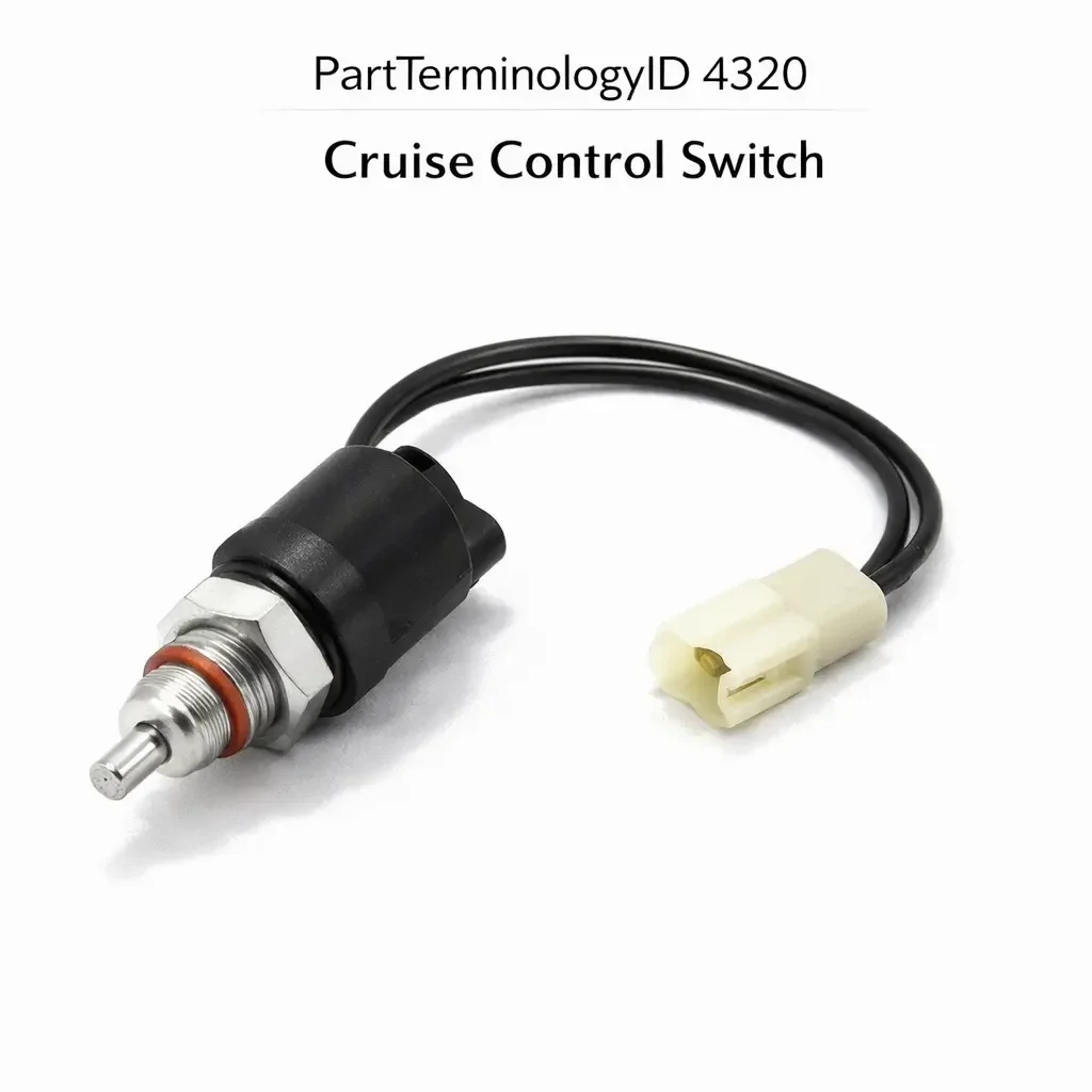
Cruise Control Switch (PartTerminologyID 4320): Control Interface Type, Resistor Network Compatibility, and Steering Column or Steering Wheel Integration
Written by Arthur Simitian | PartsAdvisory
PartTerminologyID 4320, Cruise Control Switch, is the driver-operated input device that allows the occupant to engage, set, resume, accelerate, decelerate, and cancel the cruise control function, mounted on the steering wheel spoke, the steering column stalk, or in some applications the instrument panel, and communicating the driver's speed control commands to the cruise control module, the engine control module, or the body control module through a direct wired contact array, a resistor network that encodes each button function as a unique resistance value on a single signal wire, or a serial communications bus where each button press generates a digital command on the vehicle network. That definition covers the driver input and command transmission function correctly and leaves unresolved every question that determines whether the replacement switch produces the correct signal type and signal values for each function button on the specific vehicle's cruise control circuit architecture, whether the switch connector pin count and terminal assignment match the harness at the steering wheel or column stalk mounting position, whether the switch physical form factor and button layout match the original at the steering wheel spoke position so the driver can operate the switch without looking away from the road, whether the switch is compatible with the clockspring or spiral cable assembly that carries the steering wheel switch signals from the rotating wheel to the fixed vehicle harness, whether the switch resistor network values for each button position match the module's calibration lookup table for the specific vehicle, whether the replacement covers all original function buttons including set, coast, resume, accelerate, and cancel or whether some functions are absent in a lower-specification replacement, and whether the switch is compatible with an adaptive cruise control system that includes gap distance setting and following distance adjustment functions in addition to the standard speed setting functions.
It does not specify the signal type, resistor network values, connector pin count, terminal assignment, form factor, clockspring compatibility, function button count, or adaptive cruise control compatibility. A listing under PartTerminologyID 4320 that states only year, make, and model without signal type and resistor network values cannot be evaluated by a technician replacing a failed steering wheel cruise control switch on a vehicle where the cruise control module identifies each button function by measuring the resistance presented by the switch on a single signal wire, and the replacement switch's resistor network produces different resistance values at two of the five button positions than the module's calibration table expects, causing the module to command an incorrect cruise control function (for example, executing a resume command when the driver presses the set button) on those two positions.
For sellers, PartTerminologyID 4320 is the driver input PartTerminologyID with the highest safety consequence after the brake light switch, because a cruise control switch that commands an incorrect function when a specific button is pressed introduces a latency between the driver's intended speed control command and the vehicle's actual response, and in the case of a resistance mismatch that maps the decelerate button to the accelerate function, the vehicle response to the driver's deceleration input is the opposite of the intended command. This category of mismatch is not detectable at installation and only manifests when the specific mismatched button is pressed at highway speed, placing the driver in a position of unexpected vehicle behavior that requires recognition, reaction, and brake intervention.
What the Cruise Control Switch Does
Direct Contact Array Architecture and the Multi-Wire Signal Approach
The direct contact array architecture is used on steering column stalk switches and on some steering wheel switches where each function button is wired to a dedicated contact pair in the harness, with each contact pair connecting a specific circuit line to ground or to a supply voltage when the corresponding button is pressed. In this architecture, the switch connector has one wire per function plus a common ground or common supply, producing a connector pin count equal to the number of functions plus one.
A five-function switch (on/off, set/decelerate, resume/accelerate, cancel, and coast) in a direct contact array architecture uses a six-pin connector. Each function produces a unique combination of active and inactive contact pairs that the cruise control module or ECU decodes. The replacement switch must produce exactly the same contact pair activation for each function as the original. A switch with a different contact assignment for any function will command the wrong cruise control function when that button is pressed.
The direct contact array architecture is the easiest to verify because each function can be tested independently with a continuity tester by confirming which pin pairs make contact when each button is pressed. A replacement switch can be verified against the original contact map before installation on any vehicle with a direct contact array architecture. The listing must state the pin count and provide a contact map or function-to-pin assignment table for every direct contact array switch.
Resistor Network Architecture and the Single-Wire Signal Encoding Approach
The resistor network architecture is used extensively on steering wheel spoke switches from the mid-1990s onward, where minimizing the number of wires routed through the clockspring is a packaging priority. In this architecture, all cruise control button functions are encoded as different resistance values on a single signal wire, with a pull-up resistor inside the cruise control module or ECU maintaining a reference voltage on the signal wire and each button function connecting a specific resistor to ground, pulling the signal wire to a unique voltage level that the module's analog-to-digital converter maps to the corresponding function command.
A five-function resistor network switch may use resistor values of 0 ohms (short to ground for cancel), 220 ohms (set/decelerate), 680 ohms (resume/accelerate), 1500 ohms (coast), and 4700 ohms (on/off), with the module's calibration table mapping each voltage window on the signal wire to the corresponding function. The exact resistor values are specific to the vehicle manufacturer's calibration table and differ between manufacturers and model families. A replacement switch from a different manufacturer or a different model family with different resistor values will produce voltage levels that the module maps to different or undefined functions, or that fall between the voltage windows for any defined function and produce no response at all.
The resistor network architecture is the most common return cause in this PartTerminologyID because the resistor values are rarely stated in general catalog listings and are frequently assumed to be standardized when they are not. The replacement switch must match the original resistor network values exactly, confirmed from the original part number cross-reference or the vehicle manufacturer's circuit diagram. A listing that does not state the resistor values for each button position cannot be verified before purchase.
Serial Bus Architecture and the Digital Command Approach
On vehicles produced from the mid-2000s onward with LIN bus, CAN bus, or proprietary serial network architectures for steering wheel switch communication, the cruise control switch buttons generate digital messages on the vehicle network rather than analog resistance values or direct contact closures. The switch contains a small microcontroller that encodes each button press as a specific digital message transmitted on the serial bus, and the receiving module decodes the message to identify the commanded function.
In this architecture, the replacement switch must be programmed with the correct message identifiers for the specific vehicle's network protocol. An aftermarket switch that transmits generic or incorrect message identifiers will not be recognized by the receiving module, producing no cruise control response to any button press. Some serial bus cruise control switches require module initialization or VIN-specific programming after installation, similar to the programming requirement for keyless entry remotes or body control modules. The listing must state whether the replacement requires post-installation programming and must specify the programming method (dealer scan tool, aftermarket scan tool with specific software, or automatic self-initialization on first ignition cycle).
Clockspring Compatibility and the Steering Wheel Switch Interface
The cruise control switch on a steering wheel spoke communicates with the vehicle harness through the clockspring (also called the clock spring, spiral cable, or squib connector), which is the coiled ribbon cable assembly in the steering column hub that maintains electrical continuity between the rotating steering wheel and the fixed vehicle harness through the full range of steering wheel rotation. The clockspring carries the cruise control switch signal wires, the horn circuit, and in vehicles with steering wheel airbags, the airbag squib circuit.
The cruise control switch replacement must be compatible with the clockspring's signal wire count and terminal assignment for the cruise control circuit. A replacement switch with more signal pins than the clockspring's cruise control circuit provides will have unused pins that cannot be connected. A replacement switch with a different terminal assignment than the clockspring's circuit wiring will map button functions to incorrect signal wires, producing the same function mismatch as a resistor network value mismatch.
The clockspring's cruise control terminal count and assignment are typically fixed for the specific steering wheel and column combination and do not change with trim level upgrades. However, on platforms where the cruise control was an optional feature, the clockspring on a non-cruise-equipped vehicle may not include the cruise control signal wires at all. Installing a cruise control switch on a vehicle whose clockspring does not provide the cruise control signal circuit requires clockspring replacement as a prerequisite, not just switch replacement.
Adaptive Cruise Control Switch Functions and Gap Distance Control
Adaptive cruise control (ACC) systems add gap distance setting and following distance adjustment to the standard cruise control speed set, resume, and cancel functions. The ACC switch includes additional buttons for gap distance selection (typically three or four gap settings from close to far) and in some implementations a button for temporary speed override or traffic jam assist activation.
A standard cruise control switch replacement does not include the ACC gap distance control buttons and cannot substitute for an ACC switch even if the speed set, resume, and cancel resistor values or contact assignments match. The ACC control module receives gap distance commands on the same signal wire or bus as the speed commands, and the absence of gap distance button inputs after an ACC switch is replaced with a standard switch will leave the gap distance at the last stored value with no ability to adjust, which may not be immediately apparent but will be noticed in the first adaptive cruise control engagement.
The ACC button count, resistor values for gap distance buttons, and connector pin count must all be stated in listings covering adaptive cruise control switch applications.
Steering Wheel Button Layout, Form Factor, and Driver Safety Interface
Why button position and tactile profile matter for highway use
The cruise control switch is operated by the driver at highway speed without the driver looking at the switch. The driver locates the correct button by feel, using the button position relative to the steering wheel spoke edge and the button's tactile profile (raised, recessed, flat, or contoured) to distinguish set from resume from cancel without visual confirmation. A replacement switch with a different button layout or a different tactile profile from the original requires the driver to relearn the switch geography, during which time button identification errors are possible at highway speed.
A replacement that positions the cancel button where the original had the resume button, or that uses flat uniform buttons where the original used contoured buttons with distinct heights for each function, increases the probability of a wrong-function press during the relearning period. This is not a quality defect in the replacement switch but a layout mismatch that the listing should note where the replacement differs from the original button layout.
Form factor compatibility and the spoke mounting interface
Steering wheel cruise control switches are designed to fit specific steering wheel spoke shapes and mounting interfaces. The switch body contour, mounting clip positions, and back plate geometry are specific to the steering wheel's spoke profile and the switch retention channel in the spoke. A switch body that does not match the spoke profile will not sit flush against the spoke surface, leaving a gap at the switch perimeter that is immediately visible and unsatisfying to the occupant regardless of whether all functions operate correctly.
The switch retention method (snap-fit clips, screw retention, or adhesive backing) must match the steering wheel's switch cavity design. A snap-fit switch in a steering wheel that uses screw retention will not be retained securely and may be pushed back into the spoke cavity by the driver's thumb pressure during heavy button use, eventually losing contact with the clockspring terminals.
Why This Part Generates Returns
Buyers return cruise control switches because the resistor network values at two button positions differ from the module's calibration table, causing the module to execute a resume command when the set button is pressed at highway speed and producing an unexpected speed increase rather than the expected speed hold; the switch connector is a five-pin direct contact array and the harness at the steering wheel position has a three-pin resistor network connector, preventing mating; the switch is a standard cruise control type and the application requires an adaptive cruise control type with gap distance buttons, leaving the gap distance permanently non-adjustable; the switch requires LIN bus initialization after installation and the listing does not disclose this requirement, leaving the buyer with a switch that produces no response on any button until the initialization procedure is completed; the button layout places cancel and resume in swapped positions relative to the original, causing a resume command to be sent when the driver intends to cancel on the first highway use; the switch body contour does not match the steering wheel spoke profile and the switch sits with a 3mm gap at the lower edge, which the dealership refuses to accept as a warranty repair; the clockspring on the vehicle does not include the cruise control signal wires because the vehicle was built without cruise control and the listing does not note the clockspring prerequisite; and the ACC switch for a 2022 model year application uses a proprietary serial protocol that requires dealer programming but the listing describes the switch as plug-and-play.
Top Return Scenarios
Scenario 1: "Resistor values mismatched at two positions, set button commands resume, unexpected acceleration at highway speed"
The buyer installs the replacement switch. Set, cancel, and on/off functions operate correctly during a parking lot test. On the first highway use, the driver presses the set button to engage cruise control at 65 mph. The module receives a resistance value that maps to the resume function rather than the set function and commands acceleration to the previously stored speed of 75 mph. The driver brakes to cancel cruise and reports the switch as defective. The resistor value at the set button position is 300 ohms in the replacement versus 220 ohms in the original, placing the resistance in the module's voltage window for the resume command.
Prevention language: "Resistor network values: Set/coast [X] ohms, Resume/accelerate [X] ohms, Cancel [X] ohms, On/off [X] ohms. These values must match the cruise control module's calibration table for this vehicle. Verify resistor values against the original switch part number before ordering. A mismatch at any button position causes the module to execute an incorrect function when that button is pressed."
Scenario 2: "Five-pin direct contact array switch, three-pin resistor network harness, connector will not mate"
The buyer's cruise control switch has a failed on/off button. The listing covers the vehicle by year and model without specifying signal architecture. The delivered switch uses a five-pin direct contact array connector. The vehicle harness has a three-pin resistor network connector at the steering wheel spoke position. The two connector bodies are incompatible and cannot be mated. The original switch used a resistor network encoding all five functions on one signal wire with two additional pins for power and ground.
Prevention language: "Signal architecture: [direct contact array, [X]-pin connector / resistor network, [X]-pin connector / serial bus, specify protocol]. This switch uses [architecture type]. Verify the signal architecture against the vehicle harness connector before ordering. Direct contact array and resistor network switch types use different connector configurations and are not interchangeable."
Scenario 3: "Standard cruise switch in ACC application, gap distance permanently non-adjustable after installation"
The buyer replaces the cruise control switch on an adaptive cruise control equipped vehicle. The listing covers the model year without specifying ACC or standard cruise equipment level. The delivered switch covers set, resume, and cancel functions but does not include gap distance control buttons. After installation, the cruise control speed functions work correctly but the gap distance cannot be adjusted from the last stored setting. In stop-and-go ACC operation, the driver cannot change the following distance from the close setting stored by a previous driver.
Prevention language: "Cruise system compatibility: [standard cruise control / adaptive cruise control with gap distance adjustment]. This switch covers [cruise type]. Verify the cruise system type before ordering. A standard cruise switch in an ACC application does not include gap distance control buttons. The gap distance will remain at the last stored value and cannot be adjusted until an ACC-compatible switch is installed."
Scenario 4: "LIN bus switch requires initialization, no response on any button until dealer programming completed"
The buyer installs the replacement switch. No button produces any cruise control response. The switch connector is correctly mated. All fuses check serviceable. The replacement switch is a LIN bus type that requires initialization with a dealer-level scan tool before the module recognizes it on the network. The listing describes the switch as direct plug-and-play with no programming required. The buyer returns the switch as defective. The switch is not defective. It requires a programming step that was not disclosed in the listing.
Prevention language: "Post-installation programming: [not required, plug-and-play / required, LIN bus initialization with [scan tool type]]. This switch [does / does not] require post-installation programming. Failure to complete the required initialization will result in no cruise control response on any button despite correct installation."
Scenario 5: "Cancel and resume button positions swapped versus original, driver sends resume command intending to cancel at 70 mph"
The buyer installs the replacement switch and tests all functions in a parking lot. All functions activate correctly when the correct buttons are identified. On the first highway cruise control engagement, the driver reaches for the cancel button by muscle memory from the original switch layout. The cancel button on the replacement is positioned where the resume button was on the original. The driver presses resume instead of cancel, which accelerates the vehicle toward the previously stored higher speed. The driver brakes to cancel.
Prevention language: "Button layout: [description of button positions relative to spoke edge, or note if layout differs from original]. If the replacement button layout differs from the original, allow a familiarization period in a controlled environment before using cruise control at highway speed. Do not rely on muscle memory from the original switch layout during the first several uses of the replacement."
Scenario 6: "Clockspring missing cruise control wires, vehicle was built without cruise, switch installation has no circuit to connect to"
The buyer purchases a cruise control switch to add the cruise control function to a vehicle built without it. The vehicle's clockspring does not include the cruise control signal circuit wires because the clockspring was specified for the non-cruise build level. After switch installation, no connections are available for the cruise switch signal wire at the clockspring slip ring terminal positions. The buyer attributes the absence to a wiring error rather than a clockspring mismatch.
Prevention language: "Clockspring prerequisite: this switch requires a clockspring with cruise control signal wires. Vehicles built without factory cruise control may use a clockspring without cruise control circuit wires. Verify that the installed clockspring includes the cruise control signal circuit before ordering the switch. Clockspring replacement may be required as a prerequisite for cruise control switch installation on non-cruise build vehicles."
Scenario 7: "Switch body contour does not match spoke profile, 3mm gap at lower edge visible at steering wheel"
The buyer installs the replacement switch. All functions operate correctly. The switch sits with a 3mm gap at the lower edge of the switch body where it meets the steering wheel spoke surface. The original switch contour was slightly curved at the lower edge to match the spoke's compound curve. The replacement uses a flat lower edge that does not conform to the spoke surface at that point. The gap is visible from the driver's seat and the dealership declines to certify the repair.
Prevention language: "Switch body contour: [matches OEM spoke profile / note any known contour differences at specific edges]. Verify the switch body contour against the steering wheel spoke profile before ordering. A switch body that does not conform to the spoke surface will leave a visible gap at the non-conforming edge regardless of correct function."
Scenario 8: "ACC switch with proprietary protocol listed as universal fit, module does not recognize switch after installation"
The buyer installs the ACC switch described as a universal fit for the model year range. The ACC module does not respond to any button press. The switch transmits messages in a generic protocol not matched to the specific vehicle's ACC module message identifier set. The ACC module ignores all messages from the switch because the message IDs do not match the module's programmed accept list.
Prevention language: "Protocol compatibility: [OEM-specific protocol for [make/model/year range] / requires VIN-specific programming after installation]. This switch is not a universal fit for all vehicles in the model year range. Verify protocol compatibility against the specific vehicle's ACC module. An ACC switch transmitting incorrect message identifiers will not be recognized by the ACC module regardless of correct installation."
Core Listing Attributes for PartTerminologyID 4320
PartTerminologyID: 4320
Component: Cruise Control Switch
Signal architecture: direct contact array, resistor network, or serial bus with protocol (mandatory, in title)
Resistor values for each button position in ohms for resistor network types (mandatory)
Contact map for each button position for direct contact array types (mandatory)
Serial bus message identifiers and programming requirement for serial bus types (mandatory)
Cruise system type: standard cruise control or adaptive cruise control with gap distance (mandatory, in title)
Connector pin count and terminal assignment (mandatory)
Function button count and labels (mandatory)
Clockspring compatibility and cruise circuit wire prerequisite (mandatory)
Button layout description relative to spoke edge (mandatory)
Switch body contour compatibility with steering wheel spoke profile (recommended)
Post-installation programming requirement: none or tool and procedure required (mandatory for serial bus types)
Mounting retention method: snap-fit, screw, or adhesive (mandatory)
Year/make/model/submodel/trim/equipment level
Note for trim levels where ACC and standard cruise use different switches on the same platform
Note for production date range where signal architecture changed from resistor network to serial bus
Note for vehicles built without cruise where clockspring replacement is a prerequisite
Catalog Checklist for ACES/PIES Teams
PartTerminologyID = 4320
Require signal architecture in title: direct contact array, resistor network, or serial bus (mandatory)
Require resistor values per button position for resistor network types (mandatory)
Require contact map for direct contact array types (mandatory)
Require cruise system type in title: standard or adaptive cruise (mandatory)
Require connector pin count and terminal assignment (mandatory)
Require function button count and labels (mandatory)
Require clockspring compatibility and cruise wire prerequisite note (mandatory)
Require post-installation programming disclosure for serial bus types (mandatory)
Prevent resistor value omission: a mismatch at any button position causes the module to execute an incorrect function; resistor values must be stated for every resistor network switch listing without exception
Prevent signal architecture omission: direct contact array and resistor network switches use different connector configurations and are not interchangeable; architecture must be confirmed before connector pin count is evaluated
Prevent standard and ACC conflation: a standard switch in an ACC application leaves gap distance permanently non-adjustable; cruise system type must be in the title for every listing
Prevent programming requirement omission: a serial bus switch requiring initialization that is listed as plug-and-play will produce a no-function result that the buyer returns as defective; programming requirement must be disclosed in the listing
Prevent clockspring prerequisite omission: a switch installed on a vehicle without cruise control circuit wires in the clockspring has no circuit to connect to; clockspring prerequisite must be noted for all listings covering potential non-cruise build vehicles
Prevent button layout mismatch: a swapped cancel and resume button position causes incorrect function commands at highway speed; button layout differences from the original must be disclosed
Differentiate from Cruise Control Module (if cataloged): the cruise control module is the electronic control unit that interprets the switch commands and modulates throttle output; a module that produces no response despite receiving correct switch signals indicates a failed module rather than a failed switch; confirm switch signal output with a scan tool before ordering a module
Differentiate from Brake Light Switch (PartTerminologyID 2862): the brake light switch provides the cruise control disengage signal when the brake pedal is pressed; a cruise control that does not disengage on braking while operating correctly on all switch inputs indicates a failed brake light switch input to the cruise module rather than a failed cruise control switch
FAQ (Buyer Language)
How do I confirm the resistor network values before ordering a replacement?
The resistor values are typically available in the vehicle's factory service manual under the cruise control switch circuit diagram, which shows the resistance for each button position. The original switch part number cross-reference to the manufacturer's specification is the most reliable confirmation. Some aftermarket suppliers state the resistor values in the listing; if they are not stated, contact the supplier before ordering, as the absence of stated values in a resistor network switch listing is itself a fitment risk indicator.
My cruise control works on some buttons but not others after replacement. What does this indicate?
A cruise control switch that functions correctly on some buttons but not others after replacement is the characteristic symptom of a resistor network value mismatch at the non-functioning button positions. The module recognizes the resistance value produced by the working buttons but receives a value outside its calibration window for the non-working buttons. Measure the resistance across the signal and ground pins at each button position on the replacement switch and compare to the module's expected values from the factory service manual.
Does the cruise control switch need to be programmed after installation?
On direct contact array and resistor network architectures, no programming is required. On serial bus architectures, programming is often required and the listing must disclose this. If the listing does not specify the programming requirement, assume it may be required for any switch produced after 2010 on a vehicle with a CAN bus or LIN bus steering wheel switch architecture, and confirm with the supplier before purchase.
Can I add cruise control to my vehicle by installing a cruise switch on the steering wheel?
Only if the vehicle's clockspring includes the cruise control signal circuit wires and the vehicle's ECU or cruise control module has the cruise control function enabled in its software calibration. Vehicles built without cruise control at the factory may have a software-disabled cruise function in the ECU that can be enabled with appropriate scan tool programming, but they may also have a completely different ECU without cruise control capability. Confirm both the clockspring wire count and the ECU cruise capability before purchasing a steering wheel cruise switch for a non-cruise vehicle.
My adaptive cruise control gap distance buttons stopped working but speed set and resume still work. Is the switch the cause?
A partial function failure where speed control functions work but gap distance buttons do not is consistent with either a failed gap distance button mechanism in the ACC switch or a resistor value mismatch specific to the gap distance button positions. Test the resistance at the gap distance button signal pin with a multimeter at each gap distance button to confirm whether the button produces a resistance output. If the button produces no resistance change, the switch button mechanism has failed at those positions and the switch requires replacement.
Related PartTerminologyIDs
Cruise Control Module (if cataloged): the control unit that receives switch commands and modulates throttle position; a module that does not respond to correct switch signals indicates a module fault; confirm switch signal output with a scan tool before replacing the module on a no-function cruise complaint
Clockspring (PartTerminologyID 2896 or similar): the rotating electrical connector assembly that carries steering wheel switch signals to the vehicle harness; a clockspring with failed cruise control signal traces produces intermittent or no cruise switch response regardless of switch condition; confirm clockspring continuity on the cruise signal circuit before replacing the switch on an intermittent cruise complaint
Brake Light Switch (PartTerminologyID 2862 or similar): the switch that sends the cruise disengage signal when the brake pedal is pressed; a cruise control that does not disengage on braking while all switch inputs function correctly indicates a failed brake light switch cruise disengage output
Throttle Position Sensor (PartTerminologyID 4352 or similar): on drive-by-wire vehicles, the cruise control module modulates the throttle actuator rather than a cable; a throttle that does not respond to cruise module commands despite correct switch input and module function indicates a throttle actuator or TPS fault rather than a switch fault
Status in New Databases
PIES/PCdb: PartTerminologyID 4320, Cruise Control Switch
PIES 8.0 / PCdb 2.0: No change in PartTerminologyID or terminology label
Final Take for PartTerminologyID 4320
Cruise Control Switch (PartTerminologyID 4320) is the driver input PartTerminologyID with the widest range of signal architecture types sharing the same PartTerminologyID, and a signal type mismatch or a resistor network value mismatch at a single button position produces a safety-relevant outcome at highway speed where the vehicle responds to the driver's speed control input with the wrong function. A resume command when the driver pressed set, or an acceleration when the driver pressed decelerate, requires immediate brake intervention at 65 or 75 mph. The signal architecture and resistor values are the two attributes that determine whether this outcome occurs and must be the first attributes confirmed before any physical fitment check.
State the signal architecture in the title. State the resistor values for each button position for resistor network types. State the contact map for direct contact array types. State the cruise system type in the title. State the connector pin count and terminal assignment. State the function button count and layout. State the clockspring prerequisite. State the programming requirement for serial bus types. For PartTerminologyID 4320, resistor network values per button position, cruise system type (standard versus adaptive), and post-installation programming requirement are the three attributes beyond signal architecture that prevent the three most consequential and least detectable return scenarios in the cruise control switch buyer population.