Courtesy Light Switch (PartTerminologyID 4316): Door Jamb Mounting Configuration, Contact Configuration, and Body Control Module Compatibility
Written by Arthur Simitian | PartsAdvisory
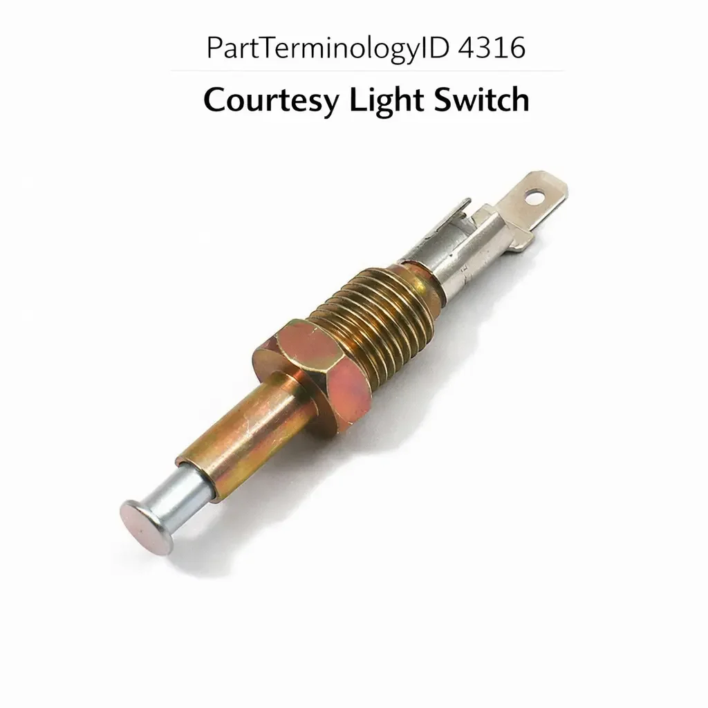
PartTerminologyID 4316, Courtesy Light Switch, is the switch mounted in the door jamb, door pillar, or door hinge pillar that detects door open and door closed positions and activates or deactivates the interior courtesy lighting circuit, triggering the dome light, map lights, footwell lights, and in modern vehicles the body control module inputs that govern welcome lighting sequences, illuminated entry timers, and door-ajar warning indicators in the instrument cluster when any door is opened or closed. That definition covers the door position detection and courtesy lighting activation function correctly and leaves unresolved every question that determines whether the replacement switch's contact configuration matches the circuit design at the installation position, whether the switch body thread specification or push-in clip geometry matches the door jamb or pillar mounting hole, whether the switch plunger travel length matches the depth of engagement when the door closes against the switch plunger, whether the replacement is compatible with the body control module's input circuit on vehicles where the BCM monitors door position through a switched ground signal rather than a direct lamp circuit, whether the switch covers a single door position or is a dual-stage type that detects both a partially open door and a fully open door as separate states, whether the switch is a normally open type that closes when the door opens or a normally closed type that opens when the door opens, whether the switch plunger button diameter and plunger head profile match the door striker or door weatherstrip contact point at the installation position, and whether the replacement is rated for the number of door open and close cycles accumulated over the vehicle's service life at the specific door position.
It does not specify the contact configuration, thread or clip mounting specification, plunger travel length, BCM input compatibility, stage count, plunger head profile, or cycle rating. A listing under PartTerminologyID 4316 that states only year, make, and model without contact configuration and mounting specification cannot be evaluated by a technician replacing a failed driver-side door jamb switch on a vehicle where the BCM expects a switched ground input (the switch connects the BCM's door input pin to ground when the door opens) and the replacement is a direct lamp circuit switch that connects battery voltage to the courtesy lamp rather than a ground signal to the BCM, which will backfeed the BCM's input pin at battery voltage and damage the BCM's input stage within the first few door open and close cycles.
For sellers, PartTerminologyID 4316 is the body electrical PartTerminologyID where the contact configuration and the circuit architecture (direct lamp circuit versus BCM input circuit) are the two attributes with the highest consequence of mismatch, because a direct lamp circuit switch installed in a BCM input position does not merely produce incorrect courtesy light behavior but actively damages the BCM's input stage by presenting battery voltage to a circuit designed for a ground signal. This damage consequence elevates PartTerminologyID 4316 from a cosmetic inconvenience category to a component safety category where the wrong replacement produces a repair cost far exceeding the switch cost and the labor required to replace it. The circuit architecture must be confirmed before any other fitment attribute is checked.
What the Courtesy Light Switch Does
Direct Lamp Circuit Architecture and the Simple Ground-Completion Function
The simplest courtesy light switch circuit connects the courtesy lamp directly between the battery positive supply (or a fused ignition-off supply) and the switch, with the switch providing the ground return path to complete the lamp circuit when the door is open. In this architecture, the switch is normally open (contacts open when the door is closed, plunger depressed) and closes when the door is opened (plunger extends), completing the ground path and illuminating the lamp. This is the direct lamp circuit architecture used on most domestic vehicles through the 1980s and on many import vehicles through the mid-1990s.
In this architecture, the switch carries the full lamp current, which for a single incandescent dome light is typically 0.5 to 2.0 amperes. The switch contacts must be rated for this current at 12 volts with the cycling frequency of normal door open and close events over the vehicle's service life. A switch with contacts rated for 0.5 amperes installed on a circuit drawing 1.5 amperes will experience accelerated contact arc erosion at each make-and-break event, producing a door light that flickers intermittently before failing to illuminate, typically after 5,000 to 15,000 door cycles depending on the severity of the current excess.
The replacement switch for a direct lamp circuit application must match the contact current rating, the contact configuration (normally open being the standard for most direct lamp circuit applications), and the switch body mounting specification. The circuit architecture itself is confirmed by checking whether the switch wire is a single wire (the lamp circuit ground return) with the lamp circuit completing through the body ground at the switch mounting position, or a two-wire harness with separate supply and ground wires (indicating a BCM input circuit or a relay-triggered circuit).
BCM Input Circuit Architecture and the Switched Ground Signal Function
On vehicles produced from the mid-1990s onward with body control modules governing the interior lighting strategy, the courtesy light switch does not carry lamp current directly. Instead, it sends a switched ground signal to the BCM's door input pin. When the door is open and the switch plunger is extended, the switch connects the BCM's door input pin to the chassis ground, pulling the input pin to ground potential. The BCM detects this ground signal and activates the courtesy lamp output through a separate internal relay or transistor output stage, which can drive multiple lamps simultaneously and implement timed dimming, welcome lighting sequences, and door-ajar detection.
In this architecture, the switch carries only the low-current BCM input signal, typically 5 to 20 milliamperes, rather than the full lamp circuit current. The contact current rating requirement is minimal, and the switch contacts are not subject to the arc erosion concern of a direct lamp circuit switch. However, the voltage at the BCM input pin (typically 5 volts supplied through a pull-up resistor inside the BCM) is critical: the BCM's input pin must see ground (0 volts) when the door is open and the pull-up voltage (5 volts) when the door is closed. A direct lamp circuit switch installed at this position connects the BCM's input pin to the lamp circuit supply voltage (12 volts) when the door is open, presenting 12 volts to a pin designed for 0 to 5 volts and potentially damaging the BCM's input protection diode or the input stage transistor.
The BCM input circuit architecture is identified by the wire gauge at the switch connector (18 to 22 AWG signal wire rather than 16 AWG lamp circuit wire), the presence of a single wire with the BCM harness connector rather than a lamp circuit connector, and in some cases the presence of a pull-up resistor visible in the circuit diagram between the BCM input pin and the 5-volt reference supply.
Dual-Stage Switches and Door-Ajar Detection
Some vehicles use a dual-stage courtesy light switch that detects two positions: a partially open door (door moved slightly off the latch but not fully swung open) and a fully open door. The partially open stage activates the door-ajar warning in the instrument cluster and the BCM's door-open status for security system purposes without triggering the full illuminated entry lighting sequence. The fully open stage triggers the complete courtesy lighting activation including the welcome sequence, footwell lighting, and map light activation.
A single-stage replacement in a dual-stage application provides only one detection level. If the single-stage switch is calibrated for the fully open position, the door-ajar warning will not activate when the door is slightly ajar (a safety concern if the driver is unaware the door is not fully latched). If the single-stage switch is calibrated for the partially open position, the full courtesy light sequence may not trigger when the door is swung fully open, producing dimmer or incomplete interior illumination than the original design provided.
The dual-stage switch uses a two-pin or three-pin connector with separate outputs for each detection stage, and a single-stage replacement will not mate correctly with the dual-stage harness connector in most cases. The stage count and connector pin count must be confirmed before ordering.
Plunger Travel, Plunger Head Profile, and the Door Jamb Engagement Geometry
The switch plunger extends when the door is opened and is depressed by the door jamb, door striker plate, or door weatherstrip when the door closes. The plunger travel length (the distance the plunger moves from the fully extended to the fully depressed position) must match the depth of engagement at the specific mounting position. A switch with a shorter plunger travel than the original may not fully depress when the door closes, leaving the switch in a partially activated state and the courtesy light partially illuminated or the BCM receiving an ambiguous input between the open and closed threshold.
A switch with a longer plunger travel than the original will be fully depressed before the door reaches the fully closed and latched position, producing correct behavior only if the extra travel is taken up by the door jamb geometry before latch engagement. On positions where the door jamb geometry precisely matches the original plunger travel, a longer plunger will bottom out before the door contacts the jamb seal fully, which may prevent the door from closing completely or may stress the switch body mounting threads as the door presses against the extended plunger beyond its designed travel.
The plunger head profile (flat, domed, or stepped) determines the contact area with the door jamb surface at the engagement point. A flat plunger head in a position designed for a domed head may produce edge contact rather than center contact, producing uneven plunger loading that causes the plunger to bind in the switch body after several thousand cycles as the edge-contact wear pattern develops an asymmetric groove in the plunger shaft guide bore.
Thread Specification, Push-In Clip Mounting, and the Door Pillar Installation Requirement
Courtesy light switches are mounted in the door jamb or pillar by one of two methods: a threaded body that screws into a threaded hole in the pillar, or a push-in clip body that snaps into a round or oval cutout in the pillar sheet metal. The thread specification for threaded installations is most commonly 3/8-24 UNF or M10 x 1.0, with some applications using larger thread bodies at door jamb positions where the switch is in a higher-load contact zone.
The push-in clip geometry (clip tab width, clip tab height, and clip body diameter) must match the door pillar cutout dimensions exactly for the switch to retain securely under the repeated vibration load of door closing events. A push-in clip switch with a slightly smaller clip body diameter than the original will rattle in the cutout under door closing vibration, producing an audible rattle from the door pillar area that is difficult to diagnose as a switch retention issue rather than a body panel looseness.
Why This Part Generates Returns
Buyers return courtesy light switches because the replacement is a direct lamp circuit type and the application is a BCM input circuit, backfeeding the BCM input pin at battery voltage and damaging the BCM input stage within the first dozen door cycles; the contact configuration is normally closed and the application requires normally open, illuminating the courtesy light only when the door is fully closed and extinguishing it when the door is opened; the plunger travel is 2mm shorter than the original and the switch does not fully depress when the door closes, leaving the BCM receiving an open-door signal with the door latched and the door-ajar warning permanently illuminated in the instrument cluster; the thread is 3/8-24 UNF and the door pillar has a push-in clip cutout rather than a threaded hole, requiring a different mounting type entirely; the switch is a single-stage type and the application requires a dual-stage type with a two-pin connector, leaving the door-ajar detection stage permanently non-functional; the plunger head is flat and the door jamb contact point is a curved striker plate that contacts the dome head of the original switch at center, producing off-center loading and a plunger that sticks in the bore after 200 cycles; the replacement contact current rating is 0.5 amperes and the direct lamp circuit draws 1.8 amperes for two dome lights and two map lights wired to the same switch, producing arc erosion and a flickering light within 3,000 door cycles; and the push-in clip body diameter is 14mm and the door pillar cutout is 16mm, causing the switch to rattle on every door close and eventually fall into the door pillar cavity.
Top Return Scenarios
Scenario 1: "Direct lamp circuit switch in BCM input position, battery voltage backfed to BCM input pin, BCM input stage damaged"
The buyer's driver-side courtesy light switch has failed, leaving the dome light permanently on. The listing covers the vehicle by year and model without specifying circuit architecture. The delivered switch is a direct lamp circuit type from a pre-BCM variant of the same platform. After installation in the BCM input circuit position, the switch connects the BCM's door input pin to the lamp circuit supply voltage (12 volts) when the door is opened. The BCM input stage, designed for a 0 to 5 volt ground-pull-down signal, receives 12 volts on every door open event. After 15 door cycles the BCM's input protection diode fails, and the door position input permanently reads closed regardless of actual door state. The door-ajar warning no longer functions and the courtesy light no longer activates on door opening.
Prevention language: "Circuit architecture: [direct lamp circuit / BCM ground-pull-down input]. This switch is the [direct lamp circuit / BCM input] type. Verify the circuit architecture before ordering. A direct lamp circuit switch in a BCM input position backfeeds the BCM input pin at battery voltage on every door open event, damaging the BCM input stage. Confirm wire gauge at the switch connector (16 AWG or heavier indicates direct lamp circuit; 18 to 22 AWG signal wire indicates BCM input circuit)."
Scenario 2: "Normally closed switch in normally open circuit, dome light on only when door is closed"
The buyer's courtesy light does not illuminate when any door is opened. The listing covers the application without specifying contact configuration. The delivered switch is normally closed. After installation, the switch contact is closed when the door is closed (plunger depressed), completing the lamp circuit and illuminating the dome light whenever the door is fully closed. When the door is opened (plunger extended), the normally closed contact opens, extinguishing the dome light. The dome light is on while driving with all doors closed and off whenever a door is opened, which is the exact opposite of the intended behavior.
Prevention language: "Contact configuration: [normally open, light activates on door open / normally closed, light activates on door close]. Verify contact configuration against the vehicle's courtesy lamp circuit design. A normally closed switch in a normally open circuit illuminates the courtesy light only when the door is fully closed and extinguishes it when the door is opened."
Scenario 3: "Plunger 2mm short, door-ajar warning permanently illuminated with door latched"
The buyer installs the replacement switch at the driver-side door jamb. The door closes and latches normally. The door-ajar warning remains illuminated in the instrument cluster with the door fully latched. The BCM's door input pin is not receiving a clean ground signal because the plunger is not fully depressed at the door-closed position, leaving the switch contact in a partially transitional state between open and closed. The BCM interprets the ambiguous signal as a door that is not fully latched.
Prevention language: "Plunger travel: [X] mm from fully extended to fully depressed. Verify plunger travel against the original switch specification and the door jamb engagement depth at the installation position. A switch with a shorter plunger travel than the original may not fully depress when the door is latched, leaving the BCM's door input in an ambiguous state and the door-ajar warning permanently illuminated."
Scenario 4: "Single-stage switch in dual-stage application, door-ajar detection stage non-functional"
The buyer installs the replacement switch. The courtesy lights activate correctly when the door is fully opened. The door-ajar warning does not illuminate when the door is cracked slightly open to the first detection stage. The replacement is a single-stage switch calibrated for the fully open position. The partially open door-ajar stage is not present in the replacement. If the driver exits the vehicle with the door not fully latched, no warning illuminates.
Prevention language: "Stage configuration: [single-stage / dual-stage with partial open and full open detection]. Connector pin count: [X] pins. This switch is the [single / dual]-stage type. A single-stage switch in a dual-stage application disables the door-ajar detection stage, removing the warning that activates when the door is not fully latched."
Scenario 5: "Push-in clip switch in threaded pillar hole, switch cannot be retained, falls into door pillar cavity"
The buyer's vehicle has a threaded M10 x 1.0 hole in the door pillar for the courtesy light switch. The listing covers the application without specifying mounting type. The delivered switch uses a push-in clip retention body. The push-in clip body cannot thread into the M10 hole and sits loosely at the hole opening without retention. On the first door close event, the switch is pushed back through the hole by the door contact force and falls into the door pillar cavity.
Prevention language: "Mounting type: [threaded body, specify thread specification / push-in clip, specify clip body diameter and cutout shape]. Verify the mounting type against the door pillar installation position. Threaded and push-in clip mounting types are not interchangeable at the same position. A push-in clip switch in a threaded hole cannot be retained and will fall into the door pillar cavity on first contact."
Scenario 6: "Contact current rating 0.5 amperes in 1.8 ampere direct lamp circuit, arc erosion and flickering within 3000 door cycles"
The buyer installs the replacement switch in a direct lamp circuit connecting two dome lights and two map lights. The total lamp current draw is 1.8 amperes. The replacement switch contacts are rated for 0.5 amperes. On each door close event, the switch opens under 1.8 amperes, producing an arc at the contact gap that ablates the contact surface at the rated current-to-contact-rating ratio. After approximately 3,000 door cycles, the contact surface erosion is sufficient to produce intermittent contact, and the dome lights flicker when the door is closed. After 5,000 cycles, the contact fails to close reliably.
Prevention language: "Contact current rating: [X] amperes. Verify the total lamp circuit current draw against the contact rating. A direct lamp circuit switch must be rated for the total current draw of all lamps connected to the circuit. Undersized contacts experience accelerated arc erosion at the door-close event and produce flickering followed by contact failure within a fraction of the expected service life."
Scenario 7: "Push-in clip body 14mm diameter in 16mm cutout, switch rattles on every door close"
The buyer installs the replacement switch at the B-pillar door jamb position. The switch functions correctly: the dome light activates on door open and deactivates on door close. After three days, the owner reports an audible rattle from the B-pillar area on every door close event. Inspection reveals the push-in clip body of the replacement switch has a 14mm diameter in a 16mm cutout. The 2mm clearance on each side allows the switch to move laterally in the cutout under the vibration impulse of the door closing, producing the rattle.
Prevention language: "Push-in clip body diameter: [X] mm. Cutout diameter required: [X] mm. Verify the clip body diameter matches the door pillar cutout. A clip body smaller than the cutout by 2mm or more will rattle under door closing vibration and will eventually migrate out of position in the cutout."
Core Listing Attributes for PartTerminologyID 4316
PartTerminologyID: 4316
Component: Courtesy Light Switch
Circuit architecture: direct lamp circuit or BCM ground-pull-down input (mandatory, in title)
Contact configuration: normally open or normally closed (mandatory, in title)
Stage configuration: single-stage or dual-stage with partial open and full open detection (mandatory)
Connector pin count and terminal type (mandatory)
Contact current rating in amperes for direct lamp circuit types (mandatory)
Plunger travel in mm from fully extended to fully depressed (mandatory)
Plunger head profile: flat, domed, or stepped (mandatory)
Mounting type: threaded body with thread specification, or push-in clip with clip body diameter and cutout shape (mandatory)
Door position: driver front, passenger front, driver rear, passenger rear, tailgate, or liftgate (mandatory)
BCM input signal type for BCM circuit applications: switched ground or switched voltage (mandatory)
Cycle rating in door open and close cycles (recommended)
Year/make/model/submodel/trim
Note for trim levels where BCM and non-BCM variants of the same platform use different circuit architectures
Note for production date range where circuit architecture changed from direct lamp to BCM input
Note for door positions with different plunger travel specifications on the same vehicle
Catalog Checklist for ACES/PIES Teams
PartTerminologyID = 4316
Require circuit architecture in title: direct lamp circuit or BCM input (mandatory)
Require contact configuration in title: normally open or normally closed (mandatory)
Require stage configuration: single-stage or dual-stage (mandatory)
Require connector pin count (mandatory)
Require contact current rating for direct lamp circuit types (mandatory)
Require plunger travel in mm (mandatory)
Require plunger head profile (mandatory)
Require mounting type with full thread specification or clip body diameter (mandatory)
Require door position (mandatory)
Prevent circuit architecture omission: a direct lamp circuit switch in a BCM input position backfeeds the BCM input pin at battery voltage and damages the BCM input stage; circuit architecture must be the first confirmed attribute for every listing without exception
Prevent contact configuration omission: a normally closed switch in a normally open circuit illuminates the courtesy light only when the door is closed; contact configuration must be in the title
Prevent plunger travel omission: a switch with a plunger travel 2mm shorter than the original will not fully depress at door close, leaving the BCM in an open-door state with the door latched; plunger travel must be stated and verified against the original
Prevent stage count omission: a single-stage switch in a dual-stage application removes the door-ajar detection stage; stage count and connector pin count must be confirmed
Prevent mounting type omission: threaded and push-in clip types are not interchangeable; a push-in clip switch in a threaded hole cannot be retained; mounting type must be confirmed before ordering
Prevent contact current rating omission: an undersized current rating in a direct lamp circuit produces arc erosion and contact failure within a fraction of the normal service life; current rating must be stated for all direct lamp circuit switch listings
Prevent BCM damage from architecture mismatch: note in catalog validation that any listing covering a post-1995 application without a BCM input circuit confirmation should be flagged for review before publication
Differentiate from Door Ajar Switch (if cataloged separately): some catalogs list the door-ajar detection stage as a separate PartTerminologyID from the courtesy light switch; confirm whether the application uses a combined courtesy light and door-ajar switch or two separate switches at different positions before ordering either component
Differentiate from Dome Light (PartTerminologyID 2832 or similar): the dome light is the lamp that the courtesy switch activates; a dome light that does not illuminate despite a functioning switch and correct circuit architecture indicates a failed lamp or a failed BCM output rather than a failed switch
FAQ (Buyer Language)
How do I know if my courtesy light switch uses a direct lamp circuit or a BCM input circuit?
Check the wire gauge at the switch connector. A single wire with 16 AWG or heavier gauge indicates a direct lamp circuit where the switch carries lamp current. A single wire with 18 to 22 AWG signal gauge, or a two-wire connector with one wire connecting to the body harness rather than directly to the dome light, indicates a BCM input circuit. On any vehicle produced after 1995 with a body control module listed in the service manual, assume the BCM input circuit architecture until confirmed otherwise.
Why is my dome light staying on after I closed the door and installed the new switch?
A dome light that remains on after door close with a new switch installed indicates one of three conditions: the plunger is not fully depressing at the door-closed position (plunger travel mismatch), the contact configuration is normally closed (the light is on when the plunger is depressed, not when it is extended), or the switch is not fully threaded into the mounting hole and the plunger is not engaging the door jamb surface. Confirm all three before attributing the symptom to a defective switch.
Can I use the same courtesy light switch for all four doors?
Only if all four door positions use the same mounting specification, the same plunger travel, and the same contact configuration. On many vehicles the front door jamb positions use a different plunger travel from the rear door jamb positions because the door seal compression depth differs between the front and rear doors. Confirm the plunger travel specification at each door position separately before ordering a common replacement for all four positions.
My door-ajar warning stays on even after replacing the switch. What else should I check?
A door-ajar warning that persists after switch replacement on a BCM input circuit application may indicate the new switch's plunger is not fully depressing when the door is latched (plunger travel too short), the BCM input stage was damaged before the switch replacement (indicating the original failed switch may have backfed the input pin), or a second door position's switch is also failed and sending an open-door signal to the BCM. Confirm which door input the BCM is detecting as open using a scan tool before replacing additional switches.
What is the cycle rating for a courtesy light switch and does it matter?
The cycle rating is the number of door open and close events the switch is designed to withstand before the contact mechanism reaches end of life. A switch rated for 100,000 cycles on a vehicle driven 15,000 miles per year with an average of 10 door cycles per day will last approximately 18 years before reaching its rated cycle count. A switch rated for 25,000 cycles on the same vehicle will reach its cycle limit in approximately 4.5 years. For high-use positions such as the driver door on a commercial vehicle, the cycle rating is a meaningful durability attribute.
Related PartTerminologyIDs
Door Ajar Switch (if cataloged separately): some applications separate the courtesy light activation function from the door-ajar detection function into two distinct switches at different positions; confirm whether the application uses a combined switch or separate switches before ordering; replacing the courtesy light switch when the door-ajar detection uses a separate switch will not resolve a door-ajar warning complaint
Dome Light (PartTerminologyID 2832 or similar): the interior lamp that the courtesy light switch activates in a direct lamp circuit; a dome light that does not illuminate after switch replacement confirms the lamp or its circuit rather than the switch as the remaining fault
Body Control Module (if cataloged): the module that receives the BCM input circuit switch signal and activates the interior lighting output; a BCM with a damaged input stage from a prior architecture mismatch will not respond to a correctly installed BCM input switch; confirm BCM input function with a scan tool before concluding the new switch is also failed
Interior Light (PartTerminologyID 2836 or similar): map lights, footwell lights, and reading lights that the BCM activates simultaneously with the dome light on door opening in modern vehicles; a BCM that activates the dome light but not the map lights on door opening indicates a BCM output fault rather than a switch fault
Status in New Databases
PIES/PCdb: PartTerminologyID 4316, Courtesy Light Switch
PIES 8.0 / PCdb 2.0: No change in PartTerminologyID or terminology label
Final Take for PartTerminologyID 4316
Courtesy Light Switch (PartTerminologyID 4316) is the body electrical PartTerminologyID where circuit architecture is the single most consequential attribute and must be confirmed before any other specification, because a direct lamp circuit switch installed in a BCM input position does not merely produce incorrect lighting behavior but actively damages the BCM input stage on every door open cycle, converting a two-dollar switch replacement into a several-hundred-dollar BCM replacement. The contact configuration is the second most consequential attribute, because a normally closed switch in a normally open circuit reverses the light-on and light-off states completely without any visual indication at installation. The plunger travel is the third, because a 2mm shortfall produces a permanent door-ajar warning that the driver cannot resolve without identifying the plunger specification as the cause.
State the circuit architecture in the title. State the contact configuration in the title. State the stage configuration and connector pin count. State the plunger travel in mm. State the plunger head profile. State the mounting type with full thread specification or clip body diameter. State the contact current rating for direct lamp circuit types. For PartTerminologyID 4316, circuit architecture, plunger travel, and contact current rating are the three attributes beyond the contact configuration that prevent the three most consequential and least recoverable return scenarios in the courtesy light switch buyer population.