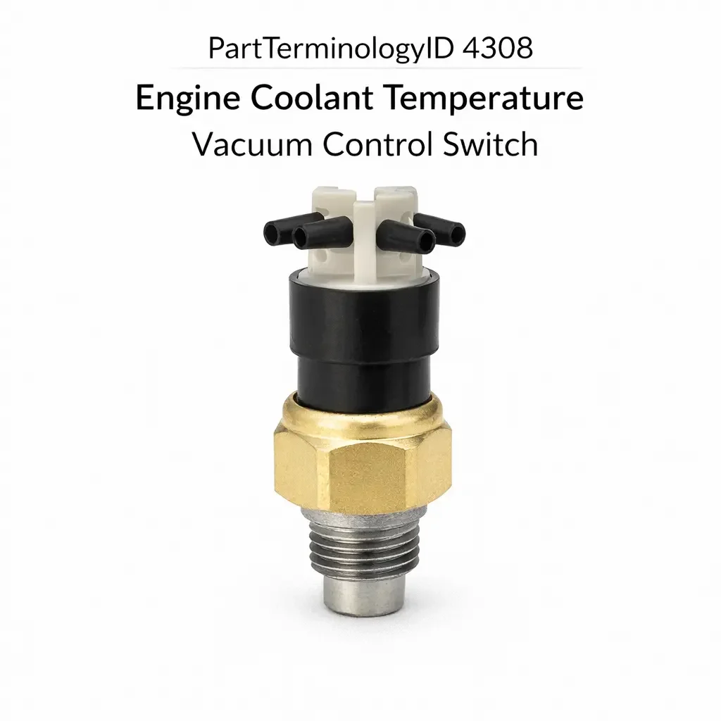
Engine Coolant Temperature Vacuum Control Switch (PartTerminologyID 4308): Temperature Threshold Calibration, Vacuum Port Configuration, and Emissions Circuit Compatibility
Written by Arthur Simitian | PartsAdvisory
PartTerminologyID 4308, Engine Coolant Temperature Vacuum Control Switch, is the thermostatic switch mounted in the engine coolant passage that monitors coolant temperature and controls the routing of engine vacuum to one or more emissions-related or drivability-related vacuum-operated devices by opening or blocking a vacuum port at a calibrated temperature threshold, most commonly used to inhibit vacuum advance to the distributor, delay EGR valve activation, control the thermostatic air cleaner's heat riser valve, or modulate the exhaust heat control valve until the engine coolant reaches normal operating temperature, preventing these vacuum-operated devices from activating during cold-start and warm-up conditions where their activation would increase emissions, cause rough idle, or produce pinging on a cold engine. That definition covers the vacuum routing and temperature gating function correctly and leaves unresolved every question that determines whether the replacement switch's temperature threshold matches the original calibration for the specific engine's warm-up profile and the specific vacuum circuit being controlled, whether the switch is a ported vacuum type that passes manifold vacuum to the controlled device above the threshold or a full vacuum type that passes vacuum below the threshold and blocks it above, whether the switch has a single vacuum port controlling one circuit or multiple vacuum ports controlling two or more circuits simultaneously from a single coolant passage mounting point, whether the thread specification matches the coolant passage port in the intake manifold or thermostat housing, whether the switch includes a bleed port that allows a small amount of vacuum to pass at all temperatures to prevent a hard vacuum lock in the controlled device, and whether the switch sealing method matches the coolant passage port to prevent coolant weeping under operating pressure.
It does not specify the temperature threshold, vacuum routing direction, port count, thread specification, bleed port configuration, or sealing method. A listing under PartTerminologyID 4308 that states only year, make, and model without temperature threshold and vacuum routing direction cannot be evaluated by a technician replacing a failed distributor vacuum advance control switch on a vehicle where the original switch blocked vacuum below 55 degrees Celsius and passed vacuum above 55 degrees Celsius to the distributor advance canister, and the replacement passes vacuum below the threshold and blocks it above, providing vacuum advance only during cold-start operation and blocking it at normal operating temperature, which is the exact opposite of the intended distributor advance calibration and will cause retarded ignition timing at cruise, elevated fuel consumption, and elevated exhaust temperature on every drive after the engine reaches operating temperature.
For sellers, PartTerminologyID 4308 is the vacuum control PartTerminologyID with the widest variation in vacuum routing direction across applications, because some circuits require vacuum to be present below the threshold (cold) and absent above it, while others require vacuum to be absent below the threshold (cold) and present above it, and a replacement that reverses the routing direction produces the opposite circuit behavior from the original on every drive after warm-up without producing any obviously identifiable installation error at the time of installation. The vacuum routing direction is as important as the temperature threshold and must be stated in the listing title or the first line of the product description.
What the Engine Coolant Temperature Vacuum Control Switch Does
Vacuum Routing Direction and the Two Switch Logic Types
The engine coolant temperature vacuum control switch is produced in two fundamental logic types that define which state the controlled vacuum circuit is in during cold operation and which state it is in after the engine reaches the threshold temperature. Understanding which logic type is required for the specific controlled circuit is the primary specification challenge in this PartTerminologyID.
The first logic type is the cold-block type, which blocks vacuum to the controlled device when the coolant is cold (below the threshold) and passes vacuum when the coolant is warm (above the threshold). This logic is used for circuits that should be inactive during cold-start and warm-up and active during normal warm operation, such as EGR valve activation circuits where EGR recirculation during cold operation would produce rough idle and increased hydrocarbon emissions, and distributor vacuum advance circuits on some applications where advance during cold operation would cause cold-start pinging on high-compression engines.
The second logic type is the cold-pass type, which passes vacuum to the controlled device when the coolant is cold (below the threshold) and blocks vacuum when the coolant is warm (above the threshold). This logic is used for circuits that should be active during cold-start and warm-up and inactive during normal warm operation, such as thermostatic air cleaner heat riser circuits where heated intake air is needed during cold operation for fuel vaporization and is no longer needed after warm-up, and early fuel evaporation (EFE) heat control valve circuits where exhaust heat applied to the intake manifold during cold operation improves cold-start emissions and driveability.
Installing a cold-block switch in a cold-pass circuit position, or vice versa, produces the exact opposite circuit behavior from the original on every drive after warm-up. The EGR valve activates during cold-start warm-up (producing rough idle) and deactivates at normal operating temperature (producing elevated NOx emissions). The thermostatic air cleaner receives no heat during cold operation (producing lean stumble and increased hydrocarbon emissions) and receives heat continuously during warm operation (producing heat soak of the intake charge and power reduction). Both outcomes are incorrect and may cause emissions test failure, but neither produces an obvious symptom at installation that would alert the technician to the routing direction mismatch.
Temperature Threshold Calibration and the Warm-Up Profile Dependency
The temperature threshold at which the switch changes state is calibrated to the specific engine's warm-up profile and the specific circuit's operational requirement. A switch controlling EGR activation on an engine that reaches operating temperature quickly in a mild climate may be calibrated to 40 degrees Celsius, allowing EGR engagement early in the warm-up cycle. A switch on the same circuit for the same engine in a cold climate variant may be calibrated to 55 degrees Celsius, delaying EGR engagement longer to prevent rough idle during the extended warm-up period in cold ambient temperatures.
A replacement switch with a threshold 15 degrees below the original will activate the EGR circuit earlier in the warm-up cycle than the original calibration intended, producing rough idle during the additional period between the lower threshold and the original threshold when the engine has not yet reached a temperature that supports stable EGR operation. A replacement with a threshold 15 degrees above the original will delay EGR activation beyond the point where the engine can sustain stable EGR operation without performance compromise, and the extended period without EGR recirculation will produce elevated NOx emissions during that window on every drive cycle.
The threshold must be confirmed from the original part number or the vehicle's emissions tune-up specification label before ordering. On vehicles where the underhood emissions label is missing or illegible, the factory service manual for the specific engine and model year is the authoritative source for the vacuum control switch threshold.
Single-Port versus Multi-Port Switch Configurations
The vacuum control switch is produced in single-port and multi-port configurations depending on the number of vacuum circuits the switch must control simultaneously from the single coolant passage mounting point. A single-port switch controls one vacuum circuit through one inlet port and one outlet port. A dual-port switch controls two vacuum circuits simultaneously, with one common vacuum supply port and two outlet ports that are both opened or both blocked at the same threshold temperature. A triple-port configuration, used on some applications where the thermostatic air cleaner, EGR, and distributor advance circuits all require the same threshold gating, provides three outlet ports from a single switch body.
A single-port replacement installed in a dual-port application leaves one vacuum circuit permanently uncontrolled: either permanently open to vacuum (if the unconnected port was previously blocked at cold) or permanently blocked from vacuum (if the unconnected port was previously open at cold). On an application where the dual-port switch controls both the EGR circuit and the distributor advance circuit, a single-port replacement that covers only the EGR port will leave the distributor advance circuit permanently at one vacuum state regardless of coolant temperature, producing either continuous vacuum advance or no vacuum advance during the entire operating temperature range.
The port count must be confirmed as a mandatory attribute for every vacuum control switch listing. A listing that does not state the port count forces the buyer to count the ports on the original switch before ordering, and a mismatch in port count is one of the most common return causes in this PartTerminologyID because the switch body dimensions and thread specification may appear identical between single and multi-port configurations.
Bleed Port Configuration and the Vacuum Lock Prevention Function
Some engine coolant temperature vacuum control switches include a small calibrated bleed orifice in the blocking element that allows a minimal amount of vacuum to pass through the blocked port at all times, preventing a hard vacuum lock in the connected device. A hard vacuum lock occurs when a vacuum-operated device is sealed at a specific vacuum level with no bleed path available: the device holds its vacuum indefinitely because there is no path for the vacuum to equalize, and the device remains in the vacuum-actuated position even after the vacuum source is removed. On a distributor advance canister, a hard vacuum lock holds the advance plate at the advanced position even after the ignition is switched off, which can produce a dieseling (run-on) condition on high-compression engines.
A replacement switch without a bleed port in an application that requires one will allow the controlled device to develop a hard vacuum lock during warm operation. A replacement with a bleed port in an application that requires a fully sealed blocking action will allow continuous low-level vacuum to reach the controlled device at all temperatures, partially activating the controlled device during the cold-block period when the circuit should be fully inhibited. The bleed port specification (present or absent, and orifice size if present) must be confirmed from the original switch specification before ordering.
Thread Specification and Sealing Method
The vacuum control switch threads into a coolant passage port in the intake manifold, thermostat housing, or coolant crossover pipe. The thread specification includes diameter, pitch, and thread form. Import applications from the emissions-control era commonly use M10 x 1.0, M12 x 1.5, or M14 x 1.5 metric threads with a copper or aluminum crush washer sealing method. Domestic applications commonly use 3/8-18 NPT or 1/8-27 NPT tapered pipe thread with thread sealant.
A tapered pipe thread switch in a straight thread coolant port will not develop a hydraulic seal against the coolant pressure, producing a coolant weep at the switch base that will worsen with each thermal cycle as the coolant passage casting expands and contracts around the incompatible thread engagement. A straight thread switch in a tapered pipe thread port will not seal through thread interference alone and requires a sealing washer that may not be present if the port was previously occupied by a tapered thread switch with sealant.
The sealing method must be stated alongside the thread specification in every listing, and the replacement must be supplied with the appropriate sealing washer or sealant recommendation for the thread form used at the application's coolant port.
Why This Part Generates Returns
Buyers return engine coolant temperature vacuum control switches because the replacement is a cold-pass type and the application requires a cold-block type, activating EGR during cold-start warm-up and blocking it at normal operating temperature, which is the exact opposite of the intended emissions control strategy and produces rough idle on every cold start and elevated NOx at normal temperature; the temperature threshold is 15 degrees below the original and the EGR circuit activates during the warm-up period before the engine can support stable EGR operation, producing rough idle on every cold morning; the switch is a single-port type and the application requires a dual-port type, leaving the distributor advance circuit permanently in one state regardless of coolant temperature; the replacement has no bleed port and the distributor advance canister develops a hard vacuum lock that holds the advance plate in the advanced position after ignition-off, producing a run-on condition on a high-compression engine; the thread is M12 x 1.5 and the coolant port is M10 x 1.0, producing a partial engagement that weeps coolant at the switch base under operating pressure; the switch is not supplied with a crush washer for the straight thread application and the buyer installs it without the sealing washer, producing an immediate coolant weep that requires switch removal, washer installation, and system refill; and the switch vacuum routing direction is correct but the threshold is 20 degrees above the original, delaying EGR activation well past the point where the engine has stabilized at operating temperature and producing an elevated NOx window on every drive cycle.
Top Return Scenarios
Scenario 1: "Cold-pass switch in cold-block circuit, EGR active during warm-up, blocked at operating temperature"
The buyer's EGR vacuum control switch has failed open, allowing continuous EGR at all temperatures including cold-start. The listing covers the vehicle by year and model without specifying vacuum routing direction. The delivered switch is a cold-pass type. After installation, the EGR circuit receives vacuum during cold-start warm-up and is blocked at normal operating temperature. The engine idles roughly for the first three to five minutes of every cold start as the EGR recirculates during the warm-up period. At operating temperature, EGR is blocked, producing elevated NOx during the drive cycle. The vehicle fails the NOx portion of the emissions test.
Prevention language: "Vacuum routing direction: [cold-block, vacuum passes above threshold / cold-pass, vacuum passes below threshold]. This switch is the [cold-block / cold-pass] type. Verify the routing direction against the original switch and the controlled circuit's operational requirement. Installing the wrong routing direction reverses the circuit behavior on every drive after warm-up without any visible installation error."
Scenario 2: "Threshold 15 degrees too low, EGR activates before engine stabilizes, rough idle on every cold morning"
The replacement switch has a threshold 15 degrees below the original. The EGR circuit activates during the lower portion of the warm-up cycle before the engine has reached a temperature that supports stable EGR operation. The engine idles roughly for two to three minutes on every cold morning between the lower threshold temperature and the original threshold temperature. The buyer attributes the rough idle to a carburetor or fuel delivery issue rather than premature EGR activation.
Prevention language: "Temperature threshold: [X] degrees Celsius. The vacuum circuit activates [above / below] this threshold. A threshold lower than the original activates the controlled circuit earlier in the warm-up cycle than the engine's calibration supports. Verify the threshold against the original switch specification or the underhood emissions tune-up label before ordering."
Scenario 3: "Single-port switch in dual-port application, distributor advance circuit permanently blocked"
The buyer's dual-port vacuum control switch has a cracked housing. The listing covers the vehicle without specifying port count. The delivered switch has one outlet port. After installation, the EGR outlet port is connected and functions correctly. The distributor advance outlet port is unconnected. The distributor advance canister receives no vacuum at any coolant temperature. The engine retards its timing relative to the original calibration, producing reduced fuel economy and elevated exhaust temperature at cruise.
Prevention language: "Port count: [single-port / dual-port / triple-port]. This switch has [X] outlet port(s). Verify the port count against the original switch. A single-port replacement in a dual-port application leaves one vacuum circuit permanently in its cold-state position regardless of coolant temperature."
Scenario 4: "No bleed port, distributor advance canister develops vacuum lock, engine diesels after ignition-off"
The original switch includes a calibrated bleed orifice that prevents a hard vacuum lock in the distributor advance canister. The replacement switch has no bleed port. After several weeks of operation, the distributor advance canister holds a hard vacuum lock with the advance plate fully advanced. When the ignition is switched off, the engine continues to fire on residual compression with the timing fully advanced (dieseling) for two to four seconds before stopping. The owner and subsequent technician replace the carburetor idle circuit before identifying the bleed port absence as the root cause.
Prevention language: "Bleed port: [present, [X] orifice size / absent]. Verify whether the original switch includes a bleed orifice before ordering. A switch without a bleed port in an application requiring one allows the controlled vacuum device to develop a hard vacuum lock that holds the device in its actuated position after the vacuum source is removed."
Scenario 5: "Crush washer not supplied, coolant weep on straight thread port at first heat cycle"
The replacement switch uses an M12 x 1.5 straight thread. The application requires a copper crush washer to seal at the thread shoulder. The switch is supplied without a crush washer and no washer is included in the packaging. The technician installs the switch without a washer. Coolant weeps from the switch base at the first operating temperature heat cycle as the coolant passage expands against the unsealed thread shoulder.
Prevention language: "Sealing method: [crush washer included / O-ring included / NPT thread sealant required]. Straight thread installations require a sealing washer at the thread shoulder. Confirm the sealing method and verify the correct washer is included with the switch before installation. A straight thread switch installed without a sealing washer will weep coolant at the thread shoulder under operating pressure."
Scenario 6: "Threshold 20 degrees too high, EGR inhibited past operating temperature stabilization, elevated NOx window"
The replacement switch threshold is 20 degrees above the original. The engine reaches stable operating temperature at 80 degrees Celsius. The EGR circuit activates at 100 degrees Celsius with the replacement switch, leaving a 20-degree window (80 to 100 degrees Celsius) during every drive cycle where the engine is fully warmed but EGR is still inhibited. The vehicle produces elevated NOx emissions during this window, which may be sufficient to cause a failure on a loaded-mode NOx emissions test that measures emissions during the initial warm operating phase.
Prevention language: "Temperature threshold: [X] degrees Celsius. A threshold above the engine's normal operating temperature stabilization point leaves the controlled emissions circuit inhibited during the initial warm operating phase. Verify the threshold is at or below the engine's normal operating temperature to prevent an elevated NOx window on the drive cycle immediately following warm-up."
Core Listing Attributes for PartTerminologyID 4308
PartTerminologyID: 4308
Component: Engine Coolant Temperature Vacuum Control Switch
Vacuum routing direction: cold-block or cold-pass (mandatory, in title)
Temperature threshold in degrees Celsius (mandatory, in title)
Port count: single, dual, or triple outlet ports (mandatory)
Controlled circuit: EGR, distributor advance, thermostatic air cleaner, EFE heat control valve, or combination (recommended)
Bleed port: present with orifice size, or absent (mandatory)
Thread specification: diameter, pitch, and thread form (mandatory)
Sealing method: crush washer, O-ring, or NPT thread sealant (mandatory, with washer inclusion note)
Switch body hex size in mm or inches (mandatory)
Year/make/model/engine/emissions package
Note for production date range where threshold or port count changed
Note for cold climate variants using higher thresholds than standard market versions
Note for multi-port applications where port assignments differ between trim levels
Catalog Checklist for ACES/PIES Teams
PartTerminologyID = 4308
Require vacuum routing direction in title: cold-block or cold-pass (mandatory)
Require temperature threshold in title (mandatory)
Require port count: single, dual, or triple (mandatory)
Require bleed port specification: present or absent (mandatory)
Require thread specification: diameter, pitch, thread form (mandatory)
Require sealing method with washer inclusion confirmation (mandatory)
Prevent vacuum routing direction omission: a cold-pass switch in a cold-block circuit reverses the controlled circuit behavior on every drive after warm-up; routing direction must be in the title for every listing without exception
Prevent threshold omission: a threshold 15 degrees below the original activates the controlled emissions circuit before the engine can support it; threshold must be stated and verified against original specification
Prevent port count omission: a single-port switch in a dual-port application permanently holds one vacuum circuit in its cold-state; port count must be confirmed as a mandatory attribute for every listing
Prevent bleed port omission: a switch without a bleed port in an application requiring one allows hard vacuum lock and engine run-on on high-compression applications; bleed port specification must be stated
Prevent sealing method omission: a straight thread switch installed without the required crush washer weeps coolant at the first heat cycle; sealing method and washer inclusion must be stated for every listing
Prevent threshold creep across cold climate variants: cold climate and standard market variants of the same engine may use different threshold calibrations; listings covering multiple market variants must specify the threshold for each variant
Differentiate from Carburetor Temperature Switch (PartTerminologyID 4272): the carburetor temperature switch controls electrical circuits to EGR and vacuum solenoids; the coolant temperature vacuum control switch controls vacuum directly without an intermediate electrical solenoid; both gate emissions circuits during warm-up but through different control mechanisms
Differentiate from Engine Coolant Temperature Sensor (PartTerminologyID 4316 or similar): the coolant temperature sensor provides a continuous analog signal to the ECU; the vacuum control switch provides a discrete vacuum on or off output at a fixed threshold; both monitor coolant temperature but serve fundamentally different circuit functions
FAQ (Buyer Language)
What is the difference between cold-block and cold-pass vacuum routing?
A cold-block switch blocks vacuum to the controlled device when the engine is cold and passes vacuum when it is warm. A cold-pass switch passes vacuum when the engine is cold and blocks it when it is warm. The correct type depends entirely on which state the controlled device (EGR valve, distributor advance canister, air cleaner heat riser) should be in during cold operation. Installing the wrong type reverses the circuit behavior after warm-up on every subsequent drive.
How do I confirm the threshold for my specific engine?
The threshold is listed on the underhood emissions tune-up label or in the factory service manual under the vacuum control switch specification for the specific engine, model year, and emissions package. On vehicles where the label is missing, the original switch part number can be cross-referenced to the manufacturer's threshold specification. Do not assume the threshold from the general application because cold climate variants and standard variants of the same engine may use different thresholds.
My EGR system works at operating temperature but the engine idles roughly for the first few minutes on cold mornings. Could this be the vacuum control switch?
Yes. Rough idle during the first few minutes of a cold start followed by normal idle after warm-up is the characteristic symptom of premature EGR activation caused by a cold-block switch with a threshold lower than the original, allowing EGR engagement during the warm-up period before the engine can support stable EGR operation. Confirm the threshold of the installed switch against the original specification before replacing the EGR valve, carburetor, or other components.
Can I use a single-port switch to replace a dual-port switch if I only need to control one circuit?
Only if the second port on the original dual-port switch was connected to a circuit that can be permanently held in one vacuum state without causing a drivability or emissions issue. In most applications, both ports control circuits that require temperature-gated vacuum regulation. Leaving one circuit permanently at one vacuum state will produce either a continuous activation of that circuit regardless of temperature or a permanent inhibition of that circuit. Confirm the function of both ports on the original switch before deciding whether a single-port replacement is acceptable.
Why is there a small hole in my original vacuum control switch?
The small hole is a bleed orifice that prevents a hard vacuum lock in the connected device. It allows a minimal amount of vacuum to bleed through the blocked port at all times so the connected device cannot hold a vacuum indefinitely when the vacuum source is removed. If the replacement switch does not have this bleed orifice and the original did, the connected device may develop a hard vacuum lock that holds it in the actuated position after the vacuum source is removed.
Related PartTerminologyIDs
Carburetor Temperature Switch (PartTerminologyID 4272): controls electrical circuits to EGR solenoids and distributor vacuum solenoids; the coolant temperature vacuum control switch controls vacuum directly; both gate emissions circuits during warm-up but through different mechanisms; confirm whether the circuit uses an electrical solenoid (pointing to PartTerminologyID 4272) or a direct vacuum switch (pointing to PartTerminologyID 4308) before ordering
EGR Valve (PartTerminologyID 4218 or similar): the valve that the vacuum control switch inhibits during cold operation; a functioning vacuum control switch with a failed EGR valve produces the same elevated NOx symptom; confirm EGR valve function by applying vacuum directly before attributing an emissions failure to the vacuum control switch
Distributor Vacuum Advance Unit (if cataloged): the advance canister that receives gated vacuum from the switch; a failed advance canister that does not respond to vacuum changes will produce retarded ignition timing regardless of vacuum control switch condition; confirm canister function by applying direct vacuum before ordering a switch replacement
Thermostatic Air Cleaner Assembly (if cataloged): the intake air temperature management system whose heat riser valve is controlled by the vacuum control switch on some applications; a failed heat riser valve or a disconnected vacuum hose will produce the same cold-start lean stumble as a failed vacuum control switch; inspect the full vacuum circuit before attributing the symptom to the switch
Status in New Databases
PIES/PCdb: PartTerminologyID 4308, Engine Coolant Temperature Vacuum Control Switch
PIES 8.0 / PCdb 2.0: No change in PartTerminologyID or terminology label
Final Take for PartTerminologyID 4308
Engine Coolant Temperature Vacuum Control Switch (PartTerminologyID 4308) is the emissions control PartTerminologyID where vacuum routing direction and temperature threshold are the two attributes that must appear in the title, because a routing direction reversal produces the exact opposite circuit behavior from the original on every warm drive cycle without any installation error visible at the time of service, and a threshold mismatch of 15 degrees produces either premature emissions circuit activation during warm-up or a delayed NOx window on every drive. Both outcomes affect emissions test compliance and drivability on the carbureted and early port fuel injected vehicle population this PartTerminologyID serves.
State the vacuum routing direction in the title. State the temperature threshold in the title. State the port count. State the bleed port specification. State the thread specification with thread form. State the sealing method with washer inclusion confirmation. For PartTerminologyID 4308, vacuum routing direction, port count, and bleed port specification are the three attributes beyond the threshold that prevent the three most consequential and least visible return scenarios in the engine coolant temperature vacuum control switch buyer population.