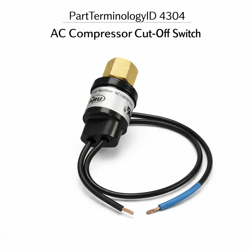
A/C Compressor Cut-Off Switch (PartTerminologyID 4304): Activation Trigger Type, Pressure and Temperature Thresholds, and Compressor Protection Circuit Compatibility
Written by Arthur Simitian | PartsAdvisory
PartTerminologyID 4304, AC Compressor Cut-Off Switch, is the switch that interrupts the A/C compressor clutch engagement circuit in response to a specific system condition that makes continued compressor operation unsafe or counterproductive, including high refrigerant pressure, low refrigerant pressure, high evaporator pressure indicating a blocked expansion device, wide-open throttle demand from the driver requesting maximum engine power, elevated engine coolant temperature approaching overheating, or a combination of these conditions depending on the vehicle's A/C system protection strategy, and differs from the A/C clutch cycle switch (PartTerminologyID 4288) in that the cut-off switch responds to an abnormal or protective condition requiring compressor disengagement rather than a normal cycling function regulating evaporator temperature. That definition covers the compressor disengagement protection function correctly and leaves unresolved every question that determines whether the replacement switch's activation trigger type matches the specific protection function the original switch performed (pressure, temperature, throttle position, or coolant temperature), whether the activation threshold matches the original calibration for the specific condition being monitored, whether the switch connector pin count and terminal type match the harness at the mounting position, whether the switch thread or mounting specification matches the installation point in the refrigerant circuit or on the engine, whether the switch is a normally open type that closes to signal a cut-off condition or a normally closed type that opens to signal cut-off depending on the ECU or relay circuit design, whether the switch body is rated for the refrigerant type and pressure in the circuit where it installs, and whether the replacement is a standalone cut-off switch or an integrated switch that combines the cut-off function with a secondary function such as condenser fan activation or an A/C request signal to the ECU.
It does not specify the activation trigger type, threshold calibration, connector pin count, thread specification, contact configuration, refrigerant rating, or integrated function content. A listing under PartTerminologyID 4304 that states only year, make, and model without activation trigger type and threshold cannot be evaluated by a technician replacing a failed cut-off switch on a vehicle where the original switch was a high-coolant-temperature type that interrupted the compressor clutch circuit when coolant temperature exceeded 115 degrees Celsius to reduce engine load during potential overheat events, and the replacement offered under the same fitment is a wide-open-throttle type that interrupts the circuit only when the throttle is at maximum travel, providing no coolant temperature protection and allowing the compressor to continue loading the engine during an overheat event.
For sellers, PartTerminologyID 4304 occupies a distinct position relative to PartTerminologyID 4284 (A/C Clutch Switch) and PartTerminologyID 4288 (A/C Clutch Cycle Switch). Where PartTerminologyID 4284 covers switches that protect the refrigerant circuit from pressure extremes, and PartTerminologyID 4288 covers switches that regulate evaporator temperature through normal cycling, PartTerminologyID 4304 covers switches that protect the engine and drivetrain from the additional load imposed by the A/C compressor under specific demanding conditions. The cut-off function is not a refrigerant circuit protection function but an engine and drivability protection function, and the activation triggers it responds to are engine-side parameters rather than refrigerant-side parameters in most applications. This distinction determines the installation position, the connector type, the threshold calibration, and the circuit architecture of the replacement switch.
What the AC Compressor Cut-Off Switch Does
Wide-Open Throttle Cut-Off and the Engine Power Demand Function
The most common AC compressor cut-off switch application on domestic vehicles from the 1970s through the early 2000s is the wide-open throttle (WOT) cut-off switch, which interrupts the compressor clutch circuit when the driver depresses the accelerator to the floor, removing the compressor's parasitic load from the engine during maximum acceleration events. At wide-open throttle, a typical 1.5 to 2.5 kW compressor load represents a measurable reduction in available engine power, particularly on small-displacement engines where the compressor load is a higher percentage of total engine output. Removing this load at WOT provides a brief but perceptible improvement in acceleration response.
The WOT cut-off switch is typically mounted at the throttle body or carburetor throttle linkage and uses a mechanical contact that closes or opens when the throttle plate reaches the maximum travel position. On fuel-injected vehicles, the WOT cut-off function may be performed by the ECU based on the throttle position sensor signal rather than by a discrete switch, but on earlier carbureted and throttle-body-injected applications the discrete WOT switch is the standard approach. The replacement for a WOT cut-off switch must match the throttle body mounting position, the mechanical contact activation geometry, and the contact configuration expected by the compressor clutch relay circuit.
High Coolant Temperature Cut-Off and the Engine Overheat Protection Function
The high coolant temperature cut-off switch interrupts the compressor clutch circuit when the engine coolant temperature rises above a calibrated threshold, typically 110 to 120 degrees Celsius, to reduce the engine's thermal load during conditions approaching overheating. The A/C compressor represents an additional heat source through its belt-driven parasitic load: the engine must do work against the compressor's compression resistance, and this work is ultimately converted to heat in the refrigerant circuit and dissipated through the condenser. When the engine is already thermally stressed, removing the compressor load reduces the engine's total heat generation and provides additional thermal headroom for the cooling system to restore normal operating temperature.
The high coolant temperature cut-off switch is mounted in the engine coolant system, either in a coolant passage port in the intake manifold or cylinder head, or in a tee fitting in the coolant hose circuit. It uses the same type of thermostatic contact mechanism as the carburetor temperature switch (PartTerminologyID 4272) and the cold start valve temperature switch (PartTerminologyID 4292), but with a threshold calibrated for the upper end of the normal operating temperature range rather than the cold-start or warm-up range. A replacement switch with a threshold 10 degrees below the original will disengage the compressor during normal operation on a hot day when the coolant temperature is elevated but still within the normal operating range, producing an intermittent A/C loss on hot days that the driver experiences as a system fault rather than a protective intervention.
Low Refrigerant Pressure Cut-Off and the Overlap with PartTerminologyID 4284
Some applications use a dedicated low-pressure cut-off switch cataloged under PartTerminologyID 4304 rather than under 4284, typically when the switch is wired to an engine management relay or a body control module input rather than directly in the compressor clutch circuit. The functional distinction between PartTerminologyID 4284 and PartTerminologyID 4304 at the low-pressure cut-off level is the circuit architecture: a low-pressure switch wired directly in the clutch coil supply circuit belongs in PartTerminologyID 4284, while a low-pressure switch that sends a signal to the ECU or BCM which then interrupts the clutch circuit through a software output belongs in PartTerminologyID 4304. Both protect the compressor from operating on a low refrigerant charge, but the circuit path and the replacement specification differ.
A replacement for a PartTerminologyID 4304 low-pressure cut-off switch must produce the signal type expected by the ECU or BCM input (typically a voltage level or a ground signal), not merely the contact closure expected in a direct-wired PartTerminologyID 4284 circuit. Installing a direct-wired contact switch in a module input circuit will either produce no signal (if the module input circuit requires a voltage level the switch cannot generate) or will ground the module input permanently (if the switch closes the module input to ground regardless of refrigerant pressure).
Integrated Cut-Off and Secondary Function Switches
Some AC compressor cut-off switches include a secondary function in the same switch body that activates a related system output at the same or a different threshold. A common configuration is a switch that cuts off the compressor at the high-pressure threshold and simultaneously activates the condenser fan at a lower intermediate threshold, combining the compressor protection and fan activation functions in a single housing with a multi-pin connector. Another configuration is a switch that cuts off the compressor at WOT and simultaneously sends an A/C-on signal to the ECU for idle speed compensation, where the ECU raises the idle speed to compensate for the compressor load when the throttle is returned to idle after a WOT event.
A replacement for an integrated cut-off and secondary function switch must include both functions in the replacement body. A replacement covering only the cut-off function leaves the secondary function output unconnected, which on an idle speed compensation application will cause the engine to stumble when the throttle is returned to idle from a WOT event because the ECU is not receiving the A/C-active signal needed to pre-position the idle air control valve. The secondary function content and the connector pin count must be confirmed for every integrated switch application.
ECU-Controlled Cut-Off and Discrete Switch Cut-Off Architectures
On modern vehicles, the compressor cut-off function is typically performed by the ECU or the climate control module based on inputs from multiple sensors (throttle position, coolant temperature, refrigerant pressure transducer) rather than by a discrete cut-off switch in the clutch circuit. In this architecture, there is no discrete AC compressor cut-off switch in the traditional sense, and the replacement component for a cut-off function failure is a sensor input (pressure transducer, coolant temperature sensor, or throttle position sensor) rather than a switch.
On older vehicles where the cut-off function is performed by a discrete switch, the ECU may still be in the circuit: the switch may send a signal to the ECU rather than directly interrupting the clutch circuit. This distinction determines whether the replacement is a contact switch (for direct-wired circuits) or a signal-producing device (for ECU-input circuits). The circuit architecture must be confirmed from the vehicle's wiring diagram before ordering, because the physical form of both switch types may appear identical while their electrical output types differ fundamentally.
Why This Part Generates Returns
Buyers return AC compressor cut-off switches because the replacement is a WOT throttle-position type and the original was a high-coolant-temperature type, providing no engine overheat load reduction and allowing the compressor to continue loading the engine during an approaching overheating event; the activation threshold is 10 degrees below the original coolant temperature calibration and the compressor cuts off on every hot afternoon drive when the coolant temperature is within the normal elevated range rather than the protective range; the contact configuration is normally closed and the relay circuit expects normally open, keeping the compressor disengaged continuously after installation; the switch is a standalone cut-off type and the application requires an integrated cut-off and idle speed compensation type, leaving the ECU's A/C-active input unconnected and producing an engine stumble on every throttle return from WOT; the thread specification is M12 x 1.5 and the coolant passage port is M10 x 1.0, producing a partial thread engagement that weeps coolant at the switch base under operating pressure; the switch produces a voltage-level output signal and the ECU input circuit expects a ground-pull-down signal, producing no cut-off response at any activation condition; and the connector is a single-pin blade and the harness at the throttle body position uses a two-pin weatherproof connector requiring a different terminal body, preventing full mating.
Top Return Scenarios
Scenario 1: "WOT switch delivered for coolant temperature cut-off application, compressor loads engine during overheat approach"
The buyer's coolant temperature cut-off switch has failed closed, leaving the compressor engaged even during coolant temperature excursions above 115 degrees Celsius. The listing covers the vehicle by year and model without specifying activation trigger type. The delivered switch is a WOT throttle-position type from the same platform's base A/C trim level. After installation at the coolant passage port, the WOT switch is physically incompatible with the coolant port mounting and cannot be installed. Even if adapted, the WOT switch provides no coolant temperature monitoring. The original coolant protection function is absent.
Prevention language: "Activation trigger type: [wide-open throttle / high coolant temperature / low refrigerant pressure / high refrigerant pressure]. This switch activates on [trigger type]. Verify the activation trigger type against the original switch. WOT, coolant temperature, and pressure cut-off switches mount at different positions on the engine and vehicle and are not interchangeable regardless of connector similarity."
Scenario 2: "Coolant temperature threshold 10 degrees too low, compressor cuts off during normal hot-day operation"
The buyer installs the replacement coolant temperature cut-off switch. On moderate days the A/C operates normally. On days above 35 degrees Celsius ambient, the engine coolant temperature reaches 105 to 108 degrees Celsius during stop-and-go traffic, which is within the normal operating range but above the replacement switch's 100 degree Celsius cut-off threshold. The compressor disengages every time the coolant temperature reaches 100 degrees in traffic. The driver experiences intermittent A/C loss on the hottest days and attributes it to a refrigerant charge issue rather than a switch threshold mismatch.
Prevention language: "Coolant temperature cut-off threshold: [X] degrees Celsius. Verify against original switch specification and the vehicle's normal maximum operating temperature. A threshold below the normal maximum operating temperature will cut off the compressor during normal hot-weather operation. The cut-off threshold must be above the normal operating temperature ceiling and below the overheat threshold."
Scenario 3: "Normally closed contact in normally open relay circuit, compressor permanently disengaged after installation"
The buyer's cut-off switch has failed open, preventing the compressor from engaging. The listing covers the application without specifying contact configuration. The delivered switch is normally closed. The relay circuit controlling the compressor clutch is designed for a normally open cut-off switch input that closes to signal a cut-off condition. After installation, the normally closed switch permanently presents a closed contact to the relay circuit, which the relay interprets as a continuous cut-off signal and keeps the compressor disengaged at all times.
Prevention language: "Contact configuration: [normally open / normally closed]. Verify contact configuration against the vehicle's compressor clutch relay circuit design. A normally closed switch in a normally open relay circuit presents a continuous cut-off signal and permanently disengages the compressor. A normally open switch in a normally closed circuit prevents the cut-off signal from ever activating."
Scenario 4: "Standalone switch in integrated cut-off and idle compensation application, engine stumbles on throttle return"
The buyer installs the replacement cut-off switch at the throttle body position. The A/C cut-off function operates correctly at WOT. However, on every return to idle from a WOT event, the engine stumbles briefly before recovering. The original switch included a secondary output pin that sent an A/C-active signal to the ECU at idle, allowing the ECU to pre-position the idle air control valve for the compressor load. The replacement switch has no secondary output pin. The ECU does not receive the A/C-active signal and cannot compensate for the compressor load at idle return.
Prevention language: "Integrated functions: [cut-off only / cut-off with idle speed compensation output / cut-off with condenser fan activation]. Connector pin count: [X] pins. Verify the secondary function content of the original switch. A standalone cut-off switch in an integrated application leaves the secondary function output unconnected and disables the ECU input used for idle speed compensation or condenser fan activation."
Scenario 5: "Voltage-level output switch in ground-pull-down ECU input circuit, no cut-off response at any condition"
The buyer installs the replacement switch at the refrigerant circuit low-pressure port. The switch connects to the ECU's low-pressure input pin. The replacement switch produces a 5-volt output signal when the pressure drops below the cut-off threshold. The ECU's low-pressure input circuit is designed for a ground-pull-down signal where the switch pulls the input pin to ground to signal a cut-off condition. The ECU never receives a recognized cut-off signal from the voltage-output switch. The compressor continues to operate below the safe minimum refrigerant charge pressure, allowing the compressor to run without adequate oil delivery.
Prevention language: "Switch output type: [voltage-level signal / ground pull-down signal / direct contact closure]. Verify the output type against the ECU or BCM input circuit specification. A voltage-level output switch in a ground pull-down input circuit will not be recognized as a cut-off signal. The ECU will not interrupt the compressor clutch circuit at any activation condition."
Scenario 6: "Thread mismatch at coolant port, coolant weep at switch base, engine coolant loss"
The buyer replaces the coolant temperature cut-off switch. The replacement thread is M12 x 1.5. The coolant passage port is M10 x 1.0. The larger M12 thread partially engages the M10 port before binding. The technician applies additional torque attempting to seat the switch against the sealing washer. The partial engagement creates a coolant leak path at the thread engagement zone. Coolant weeps from the switch base at operating pressure and temperature, requiring the switch to be removed and the port rethreaded or the affected component replaced.
Prevention language: "Thread specification: [diameter x pitch]. Verify the thread specification against the coolant passage port using a thread gauge before installation. A larger thread partially engaging a smaller port under installation torque creates a coolant leak path. Coolant loss from a damaged port may require component replacement beyond the switch."
Core Listing Attributes for PartTerminologyID 4304
PartTerminologyID: 4304
Component: AC Compressor Cut-Off Switch
Activation trigger type: WOT, high coolant temperature, low refrigerant pressure, or high refrigerant pressure (mandatory, in title)
Activation threshold in degrees Celsius for temperature types, psi for pressure types, or throttle travel percentage for WOT types (mandatory)
Contact configuration: normally open or normally closed (mandatory)
Switch output type: direct contact closure, voltage-level signal, or ground pull-down (mandatory for ECU-input applications)
Integrated secondary function: cut-off only, cut-off with idle compensation output, cut-off with condenser fan activation (mandatory)
Connector pin count and terminal type (mandatory)
Mounting position: throttle body, coolant passage port, or refrigerant circuit port (mandatory)
Thread specification for coolant and refrigerant port installations: diameter, pitch, thread form (mandatory)
Sealing method for coolant and refrigerant port installations (mandatory)
Refrigerant type compatibility for refrigerant circuit installations (mandatory)
Year/make/model/engine/A/C system configuration
Note for platforms where WOT and coolant temperature cut-off types share the same connector body
Note for ECU-controlled cut-off architectures where a discrete switch is not present
Note for integrated secondary function applications requiring multi-pin connector confirmation
Catalog Checklist for ACES/PIES Teams
PartTerminologyID = 4304
Require activation trigger type in title (mandatory)
Require activation threshold for temperature and pressure trigger types (mandatory)
Require contact configuration (mandatory)
Require switch output type for ECU-input circuit applications (mandatory)
Require integrated secondary function content and connector pin count (mandatory)
Require thread specification and sealing method for port-mounted installations (mandatory)
Require refrigerant type compatibility for refrigerant circuit installations (mandatory)
Prevent activation trigger type omission: WOT, coolant temperature, and pressure cut-off switches mount at different positions and respond to different parameters; trigger type must be in the title for every listing without exception
Prevent threshold omission: a coolant temperature cut-off threshold below the normal maximum operating temperature will disengage the compressor during normal hot-day operation; threshold must be stated and verified against the normal operating temperature ceiling
Prevent contact configuration omission: a normally closed switch in a normally open relay circuit permanently disengages the compressor; contact configuration is required for every listing
Prevent output type omission: a voltage-level output switch in a ground pull-down ECU input circuit produces no cut-off response at any activation condition; output type must be confirmed for all ECU-input circuit applications
Prevent standalone and integrated switch conflation: a standalone switch in an integrated cut-off and idle compensation application leaves the ECU idle input unconnected; secondary function content and pin count must be confirmed before ordering
Prevent thread specification omission: a larger thread partially engaging a smaller coolant or refrigerant port under installation torque creates a leak path; thread specification must be verified with a thread gauge before installation
Differentiate from A/C Clutch Switch (PartTerminologyID 4284): PartTerminologyID 4284 covers switches that protect the refrigerant circuit from pressure extremes; PartTerminologyID 4304 covers switches that protect the engine and drivetrain from compressor load under demanding engine conditions; both interrupt the compressor clutch circuit but in response to different parameters at different installation positions
Differentiate from A/C Clutch Cycle Switch (PartTerminologyID 4288): the cycling switch performs a normal regulation function that continuously cycles the compressor for evaporator temperature control; the cut-off switch performs a protective or drivability function that disengages the compressor in response to an abnormal or demanding condition; both are low-side or engine-side switches but for fundamentally different control purposes
FAQ (Buyer Language)
How does the AC compressor cut-off switch differ from the A/C clutch cycle switch?
The clutch cycle switch (PartTerminologyID 4288) cycles the compressor on and off continuously during normal A/C operation to regulate evaporator temperature on fixed-displacement compressor systems. The cut-off switch (PartTerminologyID 4304) disengages the compressor in response to a specific abnormal or demanding condition such as wide-open throttle, elevated coolant temperature, or low refrigerant pressure. The cycle switch operates on every drive. The cut-off switch operates only when the monitored condition is present.
Why does my A/C cut out during hard acceleration?
A/C cut-out during hard acceleration is the normal intended behavior of a functioning WOT cut-off switch, which removes the compressor load from the engine at maximum throttle demand. If the A/C cuts out before full throttle travel is reached, the switch activation point may be set too early in the throttle travel range, or the throttle position sensor may be signaling a higher throttle position than the actual pedal position. Confirm whether the cut-out occurs specifically at full throttle or earlier before attributing it to a switch threshold mismatch.
My A/C turns off when the engine temperature is high but comes back on when it cools. Is the switch working correctly?
Yes, if the coolant temperature at cut-off is above the normal operating range and at or near the upper threshold. This is the intended behavior of the high coolant temperature cut-off switch protecting the engine by removing compressor load during an elevated temperature event. If the cut-off occurs at normal operating temperatures on a hot day, the switch threshold is likely below the vehicle's normal maximum coolant temperature and the switch should be replaced with one calibrated to the correct upper threshold.
Can I bypass the cut-off switch if it is causing unwanted A/C cut-out?
Bypassing the cut-off switch eliminates the protection function the switch provides. Bypassing a coolant temperature cut-off switch removes the compressor load reduction during overheat events, increasing the risk of sustained overheating. Bypassing a WOT cut-off switch removes the power recovery during maximum acceleration. The correct resolution is a replacement switch calibrated to the correct threshold, not a bypass of the protection function.
How do I confirm whether my cut-off switch is wired directly in the clutch circuit or sends a signal to the ECU?
Check the wire gauge at the switch connector. A switch wired directly in the clutch coil supply circuit will have at least one wire heavy enough to carry the clutch coil current (typically 14 to 16 AWG). A switch sending a signal to the ECU will have only light-gauge signal wires (18 to 22 AWG) at the connector. The wire gauge at the connector is the quickest field confirmation of the circuit architecture before ordering the replacement.
Related PartTerminologyIDs
A/C Clutch Switch (PartTerminologyID 4284): covers high-pressure cutout, low-pressure cutout, dual-function, and trinary types that protect the refrigerant circuit; when a refrigerant pressure protection function is needed rather than an engine-side cut-off function, confirm whether the circuit architecture directs the switch to the clutch circuit directly (PartTerminologyID 4284) or to an ECU input (PartTerminologyID 4304)
A/C Clutch Cycle Switch (PartTerminologyID 4288): the cycling switch for evaporator temperature regulation on fixed-displacement compressor systems; distinct from the cut-off switch in that the cycling function is a continuous normal regulation event rather than a protective disengagement
Engine Coolant Temperature Sensor (PartTerminologyID 4316 or similar): the analog temperature sensor providing the ECU with continuous coolant temperature data; on vehicles where the high-coolant-temperature cut-off function is performed by the ECU based on the coolant temperature sensor input rather than by a discrete cut-off switch, a failed sensor may produce the same compressor cut-out symptom as a failed cut-off switch
Throttle Position Sensor (PartTerminologyID 4352 or similar): on vehicles where the WOT cut-off function is performed by the ECU based on the throttle position sensor input, a failed or miscalibrated TPS may signal WOT at partial throttle and produce premature A/C cut-out that mimics a failed WOT cut-off switch
Status in New Databases
PIES/PCdb: PartTerminologyID 4304, AC Compressor Cut-Off Switch
PIES 8.0 / PCdb 2.0: No change in PartTerminologyID or terminology label
Final Take for PartTerminologyID 4304
AC Compressor Cut-Off Switch (PartTerminologyID 4304) is the A/C system PartTerminologyID where the activation trigger type is the most consequential attribute and must appear in the title, because a WOT switch and a coolant temperature switch look nearly identical at the connector level, mount in different positions, and respond to entirely different conditions. A mismatch between trigger types produces not a visible installation error but a silent protection gap: the compressor continues to load the engine during the specific demanding condition the original switch was calibrated to relieve, and the consequence only becomes apparent when that condition is encountered on the road.
State the activation trigger type in the title. State the threshold for temperature and pressure types. State the contact configuration. State the output type for ECU-input circuits. State the integrated secondary function content and connector pin count. State the thread specification and sealing method for port-mounted installations. For PartTerminologyID 4304, activation trigger type, contact configuration, and integrated secondary function content are the three attributes beyond the standard fitment checklist that prevent the three most consequential and least visible return scenarios in the AC compressor cut-off switch buyer population.