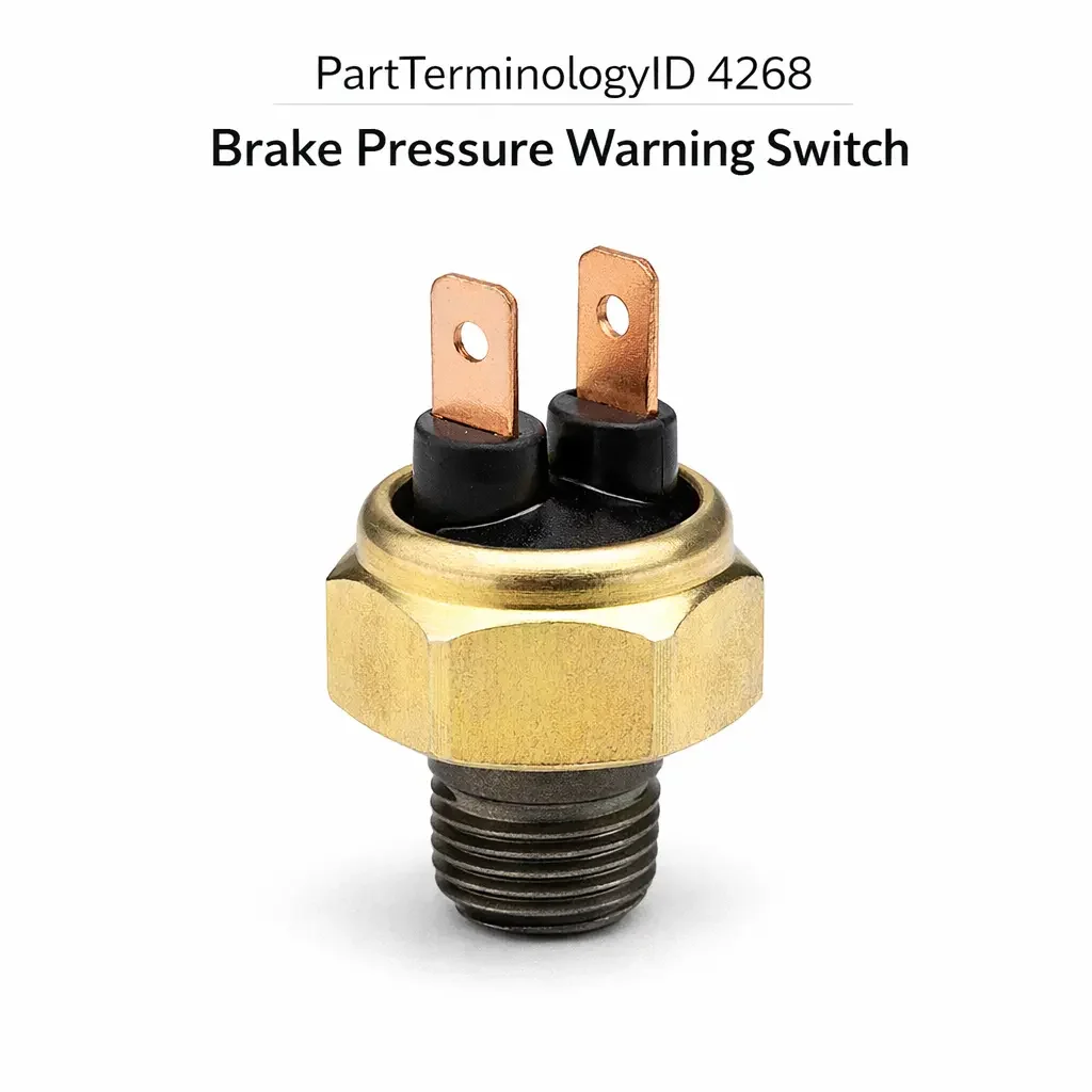
Brake Pressure Warning Switch (PartTerminologyID 4268): Pressure Threshold Calibration, Thread Specification, and Dual-Circuit Compatibility
Written by Arthur Simitian | PartsAdvisory
PartTerminologyID 4268, Brake Pressure Warning Switch, is the hydraulic pressure-sensing switch mounted in the brake system's dual-circuit hydraulic network that monitors the pressure differential between the primary and secondary brake circuits and closes an electrical contact to illuminate the brake warning lamp in the instrument cluster when the pressure in either circuit drops below the calibrated threshold, indicating a hydraulic failure in one of the two circuits that requires immediate driver attention and service. That definition covers the pressure monitoring function and the warning lamp activation correctly and leaves unresolved every question that determines whether the replacement switch's pressure activation threshold matches the original calibration for the specific vehicle's brake system operating pressure range, whether the switch thread specification (thread diameter, thread pitch, and seat type) matches the combination valve or distribution block port where the switch installs, whether the switch is a single-circuit type monitoring one hydraulic line or a differential pressure type monitoring the pressure balance between the primary and secondary circuits simultaneously through a single switch body, whether the switch electrical connector type and terminal count match the harness at the mounting position, whether the switch is a normally open type that closes on pressure drop or a normally closed type that opens on pressure drop depending on the warning lamp circuit design, whether the switch body hex size matches the available wrench clearance at the combination valve mounting position, and whether the switch is rated for the brake fluid type in the system (DOT 3, DOT 4, DOT 5, or DOT 5.1) because incompatible seal materials will swell and produce a false warning or a permanently open circuit within weeks of installation.
It does not specify the pressure activation threshold, thread specification, seat type, single-circuit or differential pressure configuration, connector type, normally open or normally closed contact configuration, hex size, or brake fluid compatibility. A listing under PartTerminologyID 4268 that states only year, make, and model without thread specification and contact configuration cannot be evaluated by a technician replacing a leaking brake pressure warning switch on a vehicle where the combination valve uses a 3/8-24 UNF thread with a conical seat and the replacement available under the same application listing uses a 10mm x 1.0 metric thread with a flat seat, because the thread forms are incompatible, the seat geometries will not seal, and installing the metric switch into the UNF port will cross-thread the combination valve port and require combination valve replacement.
For sellers, PartTerminologyID 4268 is the brake system electrical component PartTerminologyID with the most direct safety consequence after the brake light switch itself, because a failed or incorrectly installed brake pressure warning switch either leaves the driver without the warning lamp indication that a hydraulic circuit has failed (a silent safety deficiency that allows continued driving on a degraded brake system) or produces a false brake warning lamp that the driver cannot distinguish from a genuine hydraulic failure, leading either to unnecessary panic braking or to the driver ignoring a warning lamp that has previously been false. Both failure modes are safety-critical. The buyer urgency for a correctly specified replacement is correspondingly high and the tolerance for a mismatch that produces either of these outcomes is zero.
What the Brake Pressure Warning Switch Does
Dual-Circuit Brake System Architecture and the Pressure Differential Monitoring Function
Federal Motor Vehicle Safety Standard 105 requires passenger vehicles to be equipped with a dual-circuit hydraulic brake system where the front and rear brake circuits (or the diagonal split circuits on modern vehicles) are hydraulically independent, so that a single hydraulic failure disables at most half of the total braking capacity rather than the entire system. The brake pressure warning switch is the sensor that monitors the pressure relationship between the two independent circuits and alerts the driver when a pressure differential indicates that one circuit has lost hydraulic integrity.
The switch is typically mounted in the combination valve (also called the pressure differential valve or the metering and proportioning valve assembly) at the junction of the primary and secondary circuits. The combination valve contains a floating piston that remains centered when both circuits are at equal pressure. A hydraulic failure in either circuit reduces the pressure on that side of the piston, allowing the higher-pressure circuit to push the piston toward the failed circuit side. The brake pressure warning switch detects this piston displacement either directly (by sensing the piston's mechanical movement through a plunger contact) or indirectly (by sensing the pressure drop in the low-pressure circuit through a diaphragm or piston-actuated electrical contact).
Pressure Activation Threshold and the Calibration Consequence
The pressure threshold at which the switch activates the warning lamp is calibrated to the specific operating pressure range of the vehicle's brake system. A switch calibrated to activate at 100 psi pressure differential may fail to activate on a system where a slow hydraulic leak produces a 60 psi differential that is still sufficient to significantly degrade braking performance. A switch calibrated to activate at 40 psi differential may produce false warnings on a system where normal brake circuit pressure variations during aggressive braking produce transient differentials in the 30 to 50 psi range.
The pressure threshold is set by the switch manufacturer through the calibration of the internal spring that resists the diaphragm or piston movement, or through the calibration of the floating piston contact distance in a mechanically actuated design. A replacement switch with a different spring calibration will activate at a different pressure differential than the original, producing either delayed warning (if the threshold is higher than the original) or false warning (if the threshold is lower). The threshold specification is not typically printed on the switch body and must be confirmed from the manufacturer's application data or from the original equipment part number cross-reference. The listing must state the activation threshold in psi or bar for every brake pressure warning switch listing.
Single-Circuit versus Differential Pressure Switch Configurations
The brake pressure warning switch is produced in two configurations that differ in both function and installation. The single-circuit type monitors the pressure in one brake circuit only and activates the warning lamp when that circuit's pressure drops below a fixed threshold. Single-circuit types are used in applications where the two brake circuits have separate warning switch ports and each circuit has its own switch. The differential pressure type monitors the pressure relationship between two circuits simultaneously through a single switch body mounted at the combination valve, using an internal differential piston or diaphragm that responds to the pressure imbalance between the two circuit ports rather than the absolute pressure in either circuit.
A single-circuit switch installed in a differential pressure switch port connects only one hydraulic port and leaves the second port open, which will either leak brake fluid externally or allow air to enter the circuit depending on the port's pressure at installation. A differential pressure switch installed in a single-circuit port physically cannot connect to the two circuit ports required for its differential sensing function and will either not seat correctly or will produce a continuous false warning because the second port is unconnected. The switch configuration (single-circuit or differential pressure) is a mandatory attribute in every listing.
Normally Open versus Normally Closed Contact Configuration
The brake warning lamp circuit on different vehicle platforms is designed around either a normally open or a normally closed switch contact configuration. In a normally open configuration, the switch contacts are open when the brake circuits are at normal operating pressure and close when a pressure differential or pressure drop is detected, completing the warning lamp circuit and illuminating the lamp. In a normally closed configuration, the switch contacts are closed during normal operation and open when a pressure differential is detected, interrupting a circuit that keeps the warning lamp off, so the lamp illuminates when the circuit is interrupted.
Installing a normally open switch in a system designed for a normally closed switch will result in the warning lamp remaining illuminated continuously during normal operation (because the normally open contacts are always open, which the normally closed circuit design interprets as a fault) rather than extinguishing when the brake system is at normal pressure. Installing a normally closed switch in a normally open system will result in the warning lamp never illuminating even when a genuine hydraulic failure occurs (because the normally closed contacts remain closed, which the normally open circuit interprets as normal pressure). Both outcomes are safety-critical. The contact configuration must be stated in every listing and must be confirmed against the vehicle's warning lamp circuit design before ordering.
Thread Specification, Seat Type, and the Combination Valve Port Compatibility Requirement
The brake pressure warning switch installs in a threaded port in the combination valve or brake distribution block. The thread specification includes three dimensions that must all match the port: the thread diameter, the thread pitch, and the thread form (UNF, metric, or BSPP). In addition to the thread specification, the seat type (conical or flat) determines whether the switch seals against the port at the seat face (conical) or through a separate copper or aluminum crush washer (flat). A switch with a conical seat installed in a flat-seat port without a crush washer will not seal at the thread shoulder and will weep brake fluid past the seat face under system pressure. A switch with a flat seat installed in a conical-seat port will contact the conical seat at the wrong geometry and will either not seal at all or will seal only under excessive torque that risks cracking the combination valve body.
The most common thread mismatch in this PartTerminologyID is between 3/8-24 UNF (used extensively on domestic vehicles through the 1990s) and 10mm x 1.0 metric (used on most import and domestic vehicles from the mid-1990s onward). Both thread forms appear visually similar and the minor diameter difference is small enough that a metric switch will thread partially into a UNF port before binding, leading a technician to apply additional torque in an attempt to seat the switch and cross-threading the combination valve port in the process. Cross-threading a combination valve port requires combination valve replacement, which is a significantly more expensive repair than the brake pressure warning switch replacement that initiated the service.
Brake Fluid Compatibility and Seal Material Rating
The switch's internal seals (the diaphragm or piston O-ring that contacts the brake fluid in the hydraulic circuit) must be compatible with the brake fluid type in the system. DOT 3, DOT 4, and DOT 5.1 are glycol-ether based fluids that require EPDM rubber seal materials. DOT 5 is a silicone-based fluid that requires silicone-compatible seal materials and is incompatible with EPDM seals. A switch with EPDM seals installed in a DOT 5 silicone fluid system will swell within weeks as the silicone fluid permeates the EPDM material, causing the diaphragm to deform and either activate the warning lamp continuously (if the swelled diaphragm pushes the contact to the closed position) or prevent the switch from activating at all (if the swelled diaphragm binds in the open position).
DOT 5 silicone brake fluid is used in a limited range of applications including some military vehicles, some motorcycle applications, and some collector vehicles converted to silicone fluid by a previous owner. The listing must specify the brake fluid compatibility for every switch, and the buyer must confirm the brake fluid type in the system before installing. A system converted to DOT 5 by a previous owner may not have documentation of the conversion, and confirming the fluid type with a silicone fluid test strip before installation is the only reliable method on a vehicle with an unknown service history.
Why This Part Generates Returns
Buyers return brake pressure warning switches because the thread is 3/8-24 UNF and the combination valve port is 10mm x 1.0 metric, producing a partial thread engagement that cross-threads the valve port under installation torque; the contact configuration is normally open and the vehicle's warning lamp circuit requires normally closed, illuminating the brake warning lamp continuously after installation during normal brake operation; the switch is a single-circuit type and the combination valve requires a differential pressure type, leaving the second hydraulic port open and leaking brake fluid after installation; the pressure activation threshold is calibrated for a higher differential than the original and a genuine hydraulic failure on the front circuit does not activate the warning lamp at the pressure differential produced by the specific failure; the seat type is flat with a crush washer and the combination valve port has a conical seat, preventing a seal at the thread shoulder and producing a weeping brake fluid leak at the switch base that the technician initially attributes to undertorque; the switch connector is a single blade terminal and the harness connector at the combination valve position is a two-blade Metri-Pack housing, preventing mating; the seal material is EPDM and the system contains DOT 5 silicone fluid, producing a swelled diaphragm and continuous false warning within three weeks of installation; and the hex body size is 17mm and the available wrench clearance at the combination valve position with the combination valve installed in the vehicle is 14mm, requiring combination valve removal to install the switch.
Top Return Scenarios
Scenario 1: "Metric thread partially engages UNF port, cross-threads combination valve under installation torque"
The buyer's brake pressure warning switch is leaking at the thread. The listing covers the vehicle by year and model without specifying thread form. The delivered switch uses a 10mm x 1.0 metric thread. The combination valve port is 3/8-24 UNF. The metric switch threads two turns into the UNF port before the thread forms bind. The technician applies additional torque attempting to seat the switch, cross-threading the UNF port in the combination valve. The combination valve requires replacement, a repair costing significantly more than the switch replacement that initiated the service.
Prevention language: "Thread specification: [diameter x pitch, thread form: UNF / metric / BSPP]. Seat type: [conical / flat with crush washer]. Verify thread specification and seat type against the combination valve port before ordering. A metric switch partially threads into a UNF port before binding. Cross-threading the combination valve port under installation torque requires combination valve replacement."
Scenario 2: "Normally open switch installed in normally closed circuit, brake warning lamp illuminated continuously"
The buyer's brake warning lamp illuminates intermittently and the switch tests as failed. The listing covers the application without specifying contact configuration. The delivered switch is normally open. The vehicle's warning lamp circuit is designed for a normally closed switch, where the lamp is kept off by the closed circuit during normal operation and illuminates when the circuit is interrupted by a pressure differential event. After installation, the normally open switch contacts are open during normal brake operation, which the circuit interprets as a continuous fault, and the brake warning lamp illuminates at all times regardless of brake system pressure.
Prevention language: "Contact configuration: [normally open / normally closed]. Verify the contact configuration against the vehicle's warning lamp circuit design. A normally open switch in a normally closed circuit illuminates the brake warning lamp continuously during normal operation. A normally closed switch in a normally open circuit prevents the warning lamp from illuminating during a genuine hydraulic failure."
Scenario 3: "Single-circuit switch installed in differential pressure port, second port open, brake fluid leak"
The buyer's combination valve differential pressure switch is weeping fluid at the switch body. The listing covers the vehicle without specifying switch configuration. The delivered switch is a single-circuit type with one hydraulic port connection. The combination valve has two hydraulic port connections for the differential pressure switch body. After installation, the second port on the combination valve is open. Brake fluid leaks from the unoccupied port under system pressure. The brake system loses fluid and requires bleeding after the switch is removed and the correct differential pressure switch is installed.
Prevention language: "Switch configuration: [single-circuit, one hydraulic port / differential pressure, two hydraulic ports]. Verify the switch configuration against the combination valve port design. A single-circuit switch in a differential pressure port leaves the second hydraulic port open and produces an external brake fluid leak under system pressure."
Scenario 4: "EPDM seals in DOT 5 silicone fluid system, diaphragm swells, continuous false warning within three weeks"
The buyer installs the replacement switch. The brake warning lamp extinguishes at installation confirming initial function. Within three weeks the brake warning lamp illuminates continuously. Inspection confirms no hydraulic pressure differential in the brake circuits. The switch is removed and the diaphragm shows visible swelling and deformation from silicone fluid permeation of the EPDM material. The vehicle was converted to DOT 5 silicone fluid by a previous owner with no documentation of the conversion.
Prevention language: "Seal material: [EPDM, compatible with DOT 3, DOT 4, and DOT 5.1 glycol-ether fluids / silicone-compatible, required for DOT 5 silicone fluid systems]. Confirm the brake fluid type in the system before installing. On vehicles with unknown service history, test for silicone fluid with a test strip before ordering. EPDM seals in a DOT 5 system will swell within weeks and produce a continuous false warning or prevent warning lamp activation entirely."
Scenario 5: "Pressure threshold too high, front circuit failure at 60 psi differential does not activate warning lamp"
The buyer installs the replacement switch. All brake functions appear normal. During a subsequent inspection following a complaint of degraded braking, the technician identifies a failing front circuit flexible brake hose that has internally collapsed, producing a 60 psi pressure differential between the front and rear circuits. The replacement switch is calibrated to activate at 120 psi differential. The warning lamp never illuminated despite the ongoing hydraulic imbalance. The driver continued operating the vehicle on a degraded brake system without warning.
Prevention language: "Pressure activation threshold: [X] psi or [X] bar differential. Verify the activation threshold against the original switch specification. A replacement with a higher threshold than the original will not activate the warning lamp at the pressure differential produced by low-level hydraulic faults that the original switch was calibrated to detect."
Scenario 6: "17mm hex on switch body, 14mm wrench clearance at combination valve position, combination valve must be removed for installation"
The buyer orders the replacement switch for an in-vehicle installation at the combination valve without removing the combination valve from the vehicle. The replacement switch uses a 17mm hex body. The combination valve mounting position on this application is recessed between the master cylinder body and the firewall bracket, providing 14mm of wrench clearance. The switch cannot be torqued to specification in the vehicle. The combination valve must be removed from the vehicle to allow full wrench access to the switch hex, adding two hours of labor to the replacement.
Prevention language: "Switch hex size: [X] mm. Verify available wrench clearance at the combination valve position before ordering. A switch hex size larger than the available clearance requires combination valve removal for installation. Confirm clearance with the combination valve installed in the vehicle before selecting the replacement."
Core Listing Attributes for PartTerminologyID 4268
PartTerminologyID: 4268
Component: Brake Pressure Warning Switch
Switch configuration: single-circuit or differential pressure (mandatory, in title)
Contact configuration: normally open or normally closed (mandatory, in title)
Pressure activation threshold in psi and bar (mandatory)
Thread specification: diameter, pitch, and thread form (UNF, metric, or BSPP) (mandatory)
Seat type: conical or flat with crush washer (mandatory)
Connector type and terminal count (mandatory)
Switch hex body size in mm (mandatory)
Seal material and brake fluid compatibility: DOT 3/4/5.1 or DOT 5 (mandatory)
Overall installed length for clearance verification at combination valve position (recommended)
Year/make/model/submodel/trim
Note for production date range where combination valve thread specification changed
Note for vehicles converted to DOT 5 silicone fluid requiring silicone-compatible seal material
Note for combination valve positions with limited wrench clearance requiring specific hex sizes
Catalog Checklist for ACES/PIES Teams
PartTerminologyID = 4268
Require switch configuration in title: single-circuit or differential pressure (mandatory)
Require contact configuration in title: normally open or normally closed (mandatory)
Require pressure activation threshold in psi and bar (mandatory)
Require full thread specification: diameter, pitch, thread form (mandatory)
Require seat type with crush washer note for flat seat types (mandatory)
Require connector type and terminal count (mandatory)
Require hex body size in mm (mandatory)
Require seal material and brake fluid compatibility (mandatory)
Prevent thread form omission: a metric switch partially threads into a UNF port before binding; cross-threading the combination valve port requires combination valve replacement; thread form must be stated for every listing without exception
Prevent contact configuration omission: a normally open switch in a normally closed circuit illuminates the brake warning lamp continuously; a normally closed switch in a normally open circuit prevents warning lamp activation during genuine hydraulic failure; contact configuration is safety-critical and must be in the title
Prevent switch configuration omission: a single-circuit switch in a differential pressure port leaves the second hydraulic port open and produces an external brake fluid leak; switch configuration must be confirmed before ordering
Prevent pressure threshold omission: a replacement with a higher threshold than the original will fail to activate the warning lamp at pressure differentials the original was calibrated to detect; threshold must be stated and verified against original specification
Prevent seal material omission: EPDM seals in a DOT 5 silicone fluid system will swell and produce false warning within weeks; seal material and fluid compatibility must be stated for every listing
Prevent hex size omission: a switch hex larger than available wrench clearance at the combination valve position requires valve removal for installation; hex size must be stated so the buyer can verify clearance before ordering
Differentiate from Brake Light Switch (PartTerminologyID 2862 or similar): the brake light switch is a mechanical switch actuated by brake pedal travel that activates the stop lamps; the brake pressure warning switch is a hydraulic pressure sensor that activates the instrument cluster warning lamp on circuit pressure loss; both affect brake-related warning lamp circuits but monitor entirely different inputs
Differentiate from ABS Wheel Speed Sensor (if in same catalog category): the wheel speed sensor monitors individual wheel rotational speed for the ABS control module; the brake pressure warning switch monitors hydraulic circuit pressure balance; both produce brake system warning lamp indications but through different circuits and for different failure conditions
FAQ (Buyer Language)
What does the brake pressure warning switch do?
It monitors the hydraulic pressure in the dual brake circuits and closes or opens an electrical contact to illuminate the brake warning lamp in the instrument cluster when the pressure in one circuit drops, indicating a hydraulic failure that requires immediate attention. It is the sensor that tells the driver one of the two independent brake circuits has lost hydraulic integrity.
Why is my brake warning lamp on after I replaced the switch?
A brake warning lamp that illuminates continuously after switch replacement most commonly indicates a contact configuration mismatch: the replacement is normally open and the circuit requires normally closed, or vice versa. Confirm the contact configuration of the installed switch matches the original specification. If the contact configuration is correct, bleed the brake system to confirm no air was introduced during switch installation and verify that the switch is fully threaded to the correct torque without a fluid leak at the seat.
How do I confirm the thread specification before ordering?
Remove the original switch and measure the thread diameter with a thread gauge or a calibrated digital caliper at the male thread of the switch body. Compare to the thread pitch by counting threads per inch (UNF) or measuring thread pitch in millimeters (metric). If the original switch is unavailable, use a thread pitch gauge on the combination valve port threads. Do not attempt to confirm thread compatibility by starting the replacement switch in the port by hand without a thread gauge confirmation, as partial engagement before binding is the mechanism that produces cross-threading.
Can I use any brake pressure warning switch as long as it fits the port?
No. Thread form compatibility allows physical installation but does not confirm pressure threshold compatibility, contact configuration compatibility, or seal material compatibility with the brake fluid in the system. A switch that fits the port but has a higher pressure activation threshold than the original may never illuminate the warning lamp during a genuine hydraulic failure. A switch with the wrong contact configuration will either illuminate the lamp continuously or prevent illumination entirely.
My brake warning lamp was on before I replaced the switch. Now it is still on. What do I check?
Confirm the replacement switch contact configuration matches the circuit design. Confirm the brake system has been bled and there is no air in either circuit producing a genuine pressure differential. Confirm the parking brake is fully released (the parking brake warning lamp and the brake pressure warning lamp share the same instrument cluster indicator on many vehicles). If all three confirm correct, test the switch output with a multimeter to verify the switch is open (for a normally open circuit) at normal system pressure, confirming the circuit fault is upstream or downstream of the switch rather than in the switch itself.
Related PartTerminologyIDs
Brake Light Switch (PartTerminologyID 2862 or similar): the pedal-actuated switch that activates the stop lamps; shares the brake warning lamp circuit on some vehicles but monitors pedal travel rather than hydraulic pressure; a failed brake light switch produces a no-stop-lamp symptom rather than a brake warning lamp illumination
Combination Valve (if cataloged): the valve assembly in which the brake pressure warning switch mounts; a combination valve with a cross-threaded or damaged switch port requires valve replacement before a new switch can be correctly installed; inspect the port condition before ordering the switch
Brake Master Cylinder (PartTerminologyID 4264 or similar): the hydraulic pressure source for both brake circuits; a master cylinder with a failed internal seal produces a pressure differential between circuits that activates the brake pressure warning switch; confirm the master cylinder internal seal condition before concluding the switch is producing a false warning on a vehicle with no external leak
Status in New Databases
PIES/PCdb: PartTerminologyID 4268, Brake Pressure Warning Switch
PIES 8.0 / PCdb 2.0: No change in PartTerminologyID or terminology label
Final Take for PartTerminologyID 4268
Brake Pressure Warning Switch (PartTerminologyID 4268) is the brake system PartTerminologyID where a specification mismatch does not produce a minor inconvenience but a safety-critical outcome: either a driver who receives no warning during a genuine hydraulic failure, or a driver who receives a continuous false warning that trains them to ignore the brake warning lamp. Both outcomes are unacceptable and both are preventable with explicit listing attributes. The technician replacing a leaking switch needs the thread specification and seat type to avoid cross-threading the combination valve. The shop working on a post-conversion vehicle needs the seal material and brake fluid compatibility to avoid a swelled diaphragm and false warning. The buyer confirming a warning lamp complaint needs the contact configuration to avoid a continuous false warning from a normally open switch in a normally closed circuit.
State the switch configuration in the title. State the contact configuration in the title. State the pressure activation threshold. State the full thread specification including thread form. State the seat type. State the connector type and terminal count. State the hex body size. State the seal material and brake fluid compatibility. For PartTerminologyID 4268, thread form with seat type, contact configuration, and pressure activation threshold are the three attributes beyond the standard fitment checklist that prevent the three most safety-critical and least recoverable return scenarios in the brake pressure warning switch buyer population.