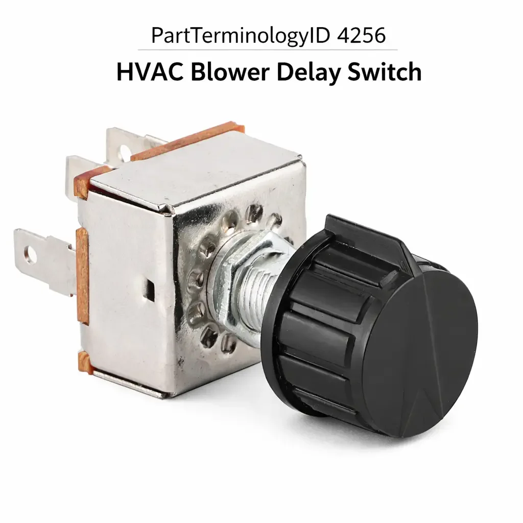
HVAC Blower Delay Switch (PartTerminologyID 4256): Delay Timing Calibration, Circuit Architecture, and Control Module Compatibility
Written by Arthur Simitian | PartsAdvisory
PartTerminologyID 4256, HVAC Blower Delay Switch, is the driver-operated or automatically activated control switch that governs the post-ignition blower operation period, allowing the HVAC blower motor to continue circulating cabin air for a defined interval after the ignition is switched off, most commonly used in conjunction with the residual heat exchanger function on diesel and alternative fuel vehicles where the coolant system retains significant thermal energy after engine shutdown and the blower delay function extracts that stored heat into the cabin rather than dissipating it through the underhood environment. That definition covers the post-ignition blower control function correctly and leaves unresolved every question that determines whether the replacement switch produces the delay timing signal or resistance output that the HVAC control module or blower delay relay expects for the specific delay interval programmed into the vehicle's climate system, whether the switch connector pin count and terminal assignment match the harness at the mounting position, whether the switch is a driver-operated manual type that allows the occupant to activate or cancel the delay on demand or an automatic type that activates the delay function without occupant input based on coolant temperature sensor data, whether the replacement is compatible with the vehicle's specific blower delay module or whether the delay timing is governed by the switch's own internal RC timing circuit, whether the switch body profile and mounting geometry match the instrument panel or center stack cutout, whether the switch includes an indicator lamp or LED element that signals the active delay period to the occupant, and whether the delay interval is fixed at a single duration or selectable across multiple duration steps.
It does not specify the delay timing calibration, connector pin count, switch type (manual or automatic), delay module compatibility, internal versus external timing architecture, switch body profile, indicator lamp type, or delay interval configuration. A listing under PartTerminologyID 4256 that states only year, make, and model without delay timing and circuit architecture type cannot be evaluated by a technician replacing a failed blower delay switch on a vehicle where the delay function is governed by an RC timing circuit internal to the switch body and the replacement switch's RC timing components are calibrated for a 20-minute delay interval while the original was calibrated for a 30-minute interval, producing a delay function that appears to operate normally but terminates 10 minutes earlier than the occupant expects on every post-ignition cycle.
For sellers, PartTerminologyID 4256 is a lower-volume but technically precise PartTerminologyID where the buyer population consists almost entirely of technicians and experienced owner-operators who have specifically diagnosed the blower delay switch as the failed component. Unlike a blower control switch failure, which produces an obvious and immediate no-blower symptom, a blower delay switch failure produces a subtler symptom: the blower operates normally during ignition-on driving but fails to continue running after ignition-off, or runs for a shorter interval than expected, or runs continuously without timing out. Each of these symptom patterns points to a specific failure mode in the switch or its associated timing circuit, and the buyer arriving at this PartTerminologyID has already performed enough diagnostic work to identify the switch as the cause.
What the HVAC Blower Delay Switch Does
Post-Ignition Blower Operation and the Residual Heat Function
The blower delay switch enables the HVAC system to continue delivering heated air into the cabin after the engine is shut off by keeping the blower motor energized through a dedicated post-ignition power circuit for a timed interval. This function is most commonly found on vehicles with diesel engines, where the coolant system retains heat at temperatures of 70 to 90 degrees Celsius for 20 to 45 minutes after shutdown, and on vehicles with auxiliary heater systems (parking heaters or coolant heaters) where the heater continues to produce hot coolant independently of the engine. In both cases, the residual thermal energy in the coolant circuit represents a significant heating resource that would otherwise be wasted if the blower motor stopped at ignition-off.
The economic argument for the blower delay function is straightforward on diesel vehicles in cold climates: a 30-minute post-ignition blower run at low speed extracts the residual coolant heat and maintains cabin temperature during a brief stop without requiring the engine to restart. The occupant returns to a warm cabin rather than a cold one, without the fuel consumption and wear associated with restarting the engine for heating purposes. The blower delay switch is the occupant-side control point for activating, adjusting, or canceling this function, and its failure eliminates the residual heat benefit entirely or causes the blower to run beyond the intended interval, drawing down the vehicle's battery if the post-ignition power circuit does not include a battery protection cutoff.
Manual Activation versus Automatic Activation Switch Types
The blower delay switch is produced in two activation types that differ fundamentally in their circuit function and replacement specification. The manual activation type is a driver-operated switch that the occupant presses or rotates to initiate the delay period before or at ignition-off. The switch sends a signal to the blower delay module or directly activates the post-ignition blower relay, and the timing function begins on switch activation. The manual type gives the occupant direct control over whether the delay function activates on any given ignition-off event, which is useful when the vehicle will be immediately restarted (making the delay function unnecessary) or when the occupant does not wish to use the residual heat on a particular stop.
The automatic activation type monitors coolant temperature through the HVAC control module and activates the blower delay function automatically when the coolant temperature at ignition-off exceeds a calibrated threshold, typically 60 to 70 degrees Celsius, indicating that sufficient residual heat is available to warrant the delay period. In this type, the switch is not a driver-operated input but a mode selector that enables or disables the automatic activation function. The occupant can disable the automatic delay for a driving session by switching the blower delay switch to the off position, but the timing and activation threshold decisions are made by the control module rather than the occupant. A replacement for an automatic activation switch must be compatible with the control module's activation logic and must produce the enable or disable signal in the format the module expects.
Internal RC Timing versus External Delay Module Timing
The delay interval in a blower delay system is governed by one of two timing architectures. The first places the RC timing circuit (a resistor-capacitor network whose time constant determines the delay duration) inside the switch body itself, so the switch contains both the occupant input mechanism and the timing electronics. In this architecture, the delay interval is determined entirely by the component values of the RC circuit inside the switch, and a replacement switch with different RC component values will produce a different delay interval even if it is physically and electrically identical in every other respect. The listing must state the delay interval in minutes for every switch that uses an internal RC timing circuit, because the interval is a direct product of the switch's internal components.
The second architecture places the timing function in a separate blower delay module mounted elsewhere in the vehicle (typically behind the instrument panel or in the HVAC module housing), and the switch's role is limited to sending an activation signal to the module. In this architecture, the switch does not determine the delay interval at all. The module does. A replacement switch for an external module timing system needs to match only the activation signal type and the connector specification, not a specific internal timing calibration. Conflating these two architectures in the listing is the primary source of timing-related returns: a buyer who receives a switch with a 20-minute internal RC calibration for a vehicle with an external timing module will find that the delay interval changes from the module-governed interval to the switch-governed interval after installation, producing an unexpected behavioral change that appears to be a defect.
Indicator Lamp and the Active Delay Status Signal
Most blower delay switches include an indicator lamp or LED element that illuminates while the delay period is active, providing the occupant with a visible confirmation that the blower will continue running after ignition-off and signaling when the delay period has ended and the blower has stopped. The indicator element is powered from the post-ignition circuit during the active delay period and extinguishes when the timing circuit opens the blower relay at the end of the delay interval.
The indicator lamp's illumination circuit voltage and current draw must match the post-ignition circuit's supply characteristics. A replacement switch with an LED indicator element drawing 20 milliamperes in a circuit designed for a 150-milliampere incandescent lamp will illuminate correctly but may produce a residual glow after the delay period ends if the circuit's discharge path does not fully dissipate the LED's lower current threshold voltage. A replacement with an incandescent indicator element in a circuit designed for LED current will draw excess current through the indicator circuit and may generate heat at the indicator lamp position sufficient to discolor the switch face.
Why This Part Generates Returns
Buyers return HVAC blower delay switches because the replacement has an internal RC timing circuit calibrated for a 20-minute delay and the vehicle's original switch was calibrated for 30 minutes, producing a shorter-than-expected delay that appears to be a defect; the replacement is an automatic activation type and the vehicle requires a manual activation type, removing the occupant's ability to initiate the delay on demand; the connector pin count is three and the harness at the mounting position has five pins, covering an activation signal, a cancel signal, a battery protection status input, a ground, and an indicator lamp feed that the three-pin replacement leaves partially unconnected; the switch produces a voltage signal output and the blower delay module expects a resistance input, causing the module to remain in the off state on every post-ignition cycle; the indicator element is a full-voltage LED and the post-ignition indicator circuit uses a reduced voltage supply, producing a dim or non-illuminating indicator that the occupant interprets as a failed delay function; and the replacement switch body uses a snap-fit retention tab geometry that differs from the original push-and-twist lock, preventing secure mounting in the instrument panel cutout.
Top Return Scenarios
Scenario 1: "Internal RC timing mismatch, delay terminates 10 minutes early on every post-ignition cycle"
The buyer's blower delay switch activates the post-ignition blower but terminates the delay after 20 minutes rather than the expected 30. The listing covers the vehicle by year and model without stating the delay interval. The delivered switch contains an internal RC timing circuit calibrated for a 20-minute interval. The vehicle's original switch used a 30-minute RC calibration. All other switch functions operate normally. The buyer returns the switch as defective because the delay interval does not match the original behavior.
Prevention language: "Delay interval: [X] minutes. Internal RC timing calibration. This switch governs the delay duration directly through its internal timing circuit. Verify the original switch's delay interval before ordering. A switch with a different RC calibration will produce a different delay interval regardless of all other compatibility attributes."
Scenario 2: "Automatic activation type delivered, vehicle requires manual activation, occupant loses on-demand control"
The buyer's manual activation blower delay switch has a failed actuator that no longer latches in the active position. The listing covers the vehicle by model without specifying activation type. The delivered switch is the automatic activation variant from the higher climate trim level on the same platform. After installation, the blower delay activates automatically on every ignition-off event above the coolant temperature threshold rather than only when the occupant manually initiates it. The occupant cannot prevent the delay from activating on brief stops where the residual heat function is unnecessary.
Prevention language: "Activation type: [manual, driver-operated / automatic, coolant temperature threshold activated]. Verify activation type against original. Manual and automatic blower delay switch types are not interchangeable. An automatic type in a manual system removes the occupant's ability to initiate or suppress the delay on demand."
Scenario 3: "Three-pin replacement in five-pin harness, battery protection status input and cancel signal unconnected"
The buyer's switch connector has corroded terminals. The listing covers the vehicle without specifying pin count. The delivered switch uses a three-pin connector covering activation signal, ground, and indicator lamp feed. The vehicle harness uses a five-pin connector that also carries a cancel signal input (allowing the occupant to terminate the delay before the timer expires by pressing the switch a second time) and a battery protection status input from the BCM (which suppresses the delay function when battery voltage falls below a threshold). After installation, the cancel function does not operate and the battery protection suppression does not function, allowing the blower to continue drawing post-ignition current even at low battery voltage.
Prevention language: "Connector pin count: [X] pins covering [activation, cancel, battery protection input, ground, indicator lamp feed]. Verify pin count and function mapping against the original harness connector. A replacement with fewer pins leaves active circuits unconnected and disables functions including cancel input and battery protection suppression."
Scenario 4: "Voltage signal output switch installed on resistance input module, module remains inactive on every post-ignition cycle"
The buyer installs the replacement switch. After ignition-off, the blower motor stops immediately with no delay period on every subsequent ignition-off event. The blower delay module is receiving a voltage signal from the new switch but its input stage is calibrated for a resistance input from a pull-down resistor network in the original switch. The voltage signal does not match the module's activation threshold and the module remains in the inactive state on every post-ignition cycle.
Prevention language: "Switch signal output type: [voltage signal / resistance input, specify range]. Verify the signal output type against the blower delay module's input specification. A voltage output switch in a resistance input module system will not activate the delay function on any post-ignition cycle."
Core Listing Attributes for PartTerminologyID 4256
PartTerminologyID: 4256
Component: HVAC Blower Delay Switch
Activation type: manual driver-operated or automatic coolant temperature threshold (mandatory, in title)
Timing architecture: internal RC circuit or external delay module (mandatory)
Delay interval in minutes for internal RC timing switches (mandatory for internal timing type)
External delay module compatibility note for external timing switches (mandatory for external timing type)
Connector pin count with function mapping for each pin (mandatory)
Switch signal output type: voltage signal or resistance with range (mandatory)
Indicator lamp type: incandescent with voltage and base type, or LED with supply voltage compatibility (mandatory)
Switch body profile and mounting retention type: snap-fit, push-and-twist, or screw mount (mandatory)
Cancel function: supported or not supported (mandatory)
Battery protection suppression input: present or absent (mandatory)
Year/make/model/submodel/trim
Note for trim levels with different activation types on the same platform
Note for production date range where delay interval or timing architecture changed
Note for vehicles with auxiliary parking heater systems requiring extended delay intervals
Catalog Checklist for ACES/PIES Teams
PartTerminologyID = 4256
Require activation type in title: manual or automatic (mandatory)
Require timing architecture: internal RC or external module (mandatory)
Require delay interval in minutes for all internal RC timing switches (mandatory)
Require connector pin count with function mapping (mandatory)
Require signal output type with range (mandatory)
Require indicator lamp type and supply voltage compatibility (mandatory)
Require mounting retention type (mandatory)
Prevent RC timing interval omission: a switch with the wrong internal RC calibration produces a delay interval that differs from the original on every post-ignition cycle; interval must be stated for every internal timing switch without exception
Prevent activation type omission: manual and automatic activation types are not interchangeable; activation type must be stated in the title for every listing
Prevent timing architecture conflation: an internal RC timing switch in an external module system transfers timing control from the module to the switch; architecture type must be confirmed before ordering
Prevent pin count omission: a replacement with fewer pins than the original harness leaves cancel input and battery protection suppression unconnected; pin count must be verified against the original harness
Prevent signal output type omission: a voltage output switch in a resistance input module system will not activate the delay function; signal type must be stated and verified against the module input specification
Differentiate from HVAC Blower Control Switch (PartTerminologyID 4252): the blower control switch governs speed during ignition-on operation; the blower delay switch governs post-ignition timed operation; both are in the HVAC control cluster but serve different circuit functions with different timing and signal requirements
Differentiate from Blower Motor Relay (if cataloged separately): the relay is the downstream power switching component that the delay switch or module activates to energize the blower post-ignition; a blower that does not run during the delay period despite a functioning switch indicates a failed relay rather than a failed switch
FAQ (Buyer Language)
What does the HVAC blower delay switch do?
It keeps the blower motor running for a timed interval after the ignition is switched off, using residual heat in the coolant system to continue warming the cabin without restarting the engine. On diesel and alternative fuel vehicles in cold climates, this function recovers stored coolant heat that would otherwise be wasted, maintaining cabin temperature during brief stops.
How do I know if my blower delay switch uses internal timing or an external module?
If the failed switch has more than four pins and one of the pins connects to a heavier gauge wire separate from the indicator lamp and ground circuits, the heavier wire likely carries the blower motor activation current through the switch itself, indicating an internal RC timing architecture. If all connector pins are light gauge signal wires, the switch is communicating with an external module that handles the timing and power switching. Confirming which architecture is present before ordering prevents the most common timing-related return.
My blower runs after ignition-off but stops sooner than it used to. Is the switch failed?
A shorter-than-original delay interval on an internal RC timing switch indicates that the RC timing capacitor has partially discharged its calibrated capacitance through leakage, reducing the time constant and shortening the delay interval. This is a genuine switch failure. If the vehicle uses an external timing module, the shorter interval may indicate a failing module rather than a failing switch, and confirming which component is at fault before ordering prevents replacing the correct component.
Can I cancel the delay period once it has started?
On switches that include a cancel input circuit, pressing the switch a second time after ignition-off sends a cancel signal to the delay module or discharges the internal RC circuit, stopping the blower immediately. On switches without a cancel input, the delay must run to completion or the vehicle must be restarted to reset the timing circuit. Confirm whether the cancel function is present in the original switch before ordering a replacement, since a replacement without the cancel function removes an occupant convenience feature.
Related PartTerminologyIDs
HVAC Blower Control Switch (PartTerminologyID 4252): the ignition-on blower speed selector; governs blower speed during normal driving operation; a failed blower control switch produces a no-blower or wrong-speed symptom during ignition-on operation, which is distinct from the post-ignition timing symptom of a failed blower delay switch
Blower Motor (PartTerminologyID 4247 or similar): the motor the delay switch keeps running post-ignition; a motor that does not run during the delay period despite a functioning switch and relay indicates a motor failure rather than a switch failure
HVAC Control Module (if applicable): the module governing automatic activation and delay timing in external module timing systems; a module that does not initiate the delay despite a correctly signaling switch indicates a module failure; confirm module function before concluding the switch replacement was ineffective
Status in New Databases
PIES/PCdb: PartTerminologyID 4256, HVAC Blower Delay Switch
PIES 8.0 / PCdb 2.0: No change in PartTerminologyID or terminology label
Final Take for PartTerminologyID 4256
HVAC Blower Delay Switch (PartTerminologyID 4256) is the climate control PartTerminologyID where timing calibration precision separates a correct repair from a subtly incorrect one that produces no obvious installation error but delivers the wrong post-ignition behavior on every subsequent ignition-off event. The technician replacing an internal RC timing switch needs the delay interval in minutes to confirm the replacement matches the original calibration. The shop working on an automatic activation system needs the activation type attribute to avoid installing a manual switch that removes the module's ability to initiate the delay automatically. The buyer on a vehicle with a five-pin harness needs the pin count and function mapping to avoid leaving the cancel input and battery protection suppression circuits unconnected.
State the activation type in the title. State the timing architecture. State the delay interval for internal RC timing switches. State the connector pin count with function mapping. State the signal output type. State the indicator lamp type and supply voltage compatibility. For PartTerminologyID 4256, delay interval calibration, activation type, and timing architecture are the three attributes that prevent the three most consequential and least visible return scenarios in the blower delay switch buyer population.