HVAC Blower Control Switch (PartTerminologyID 4252): Resistor Pack Compatibility, Signal Output Type, and Speed Step Count
Written by Arthur Simitian | PartsAdvisory
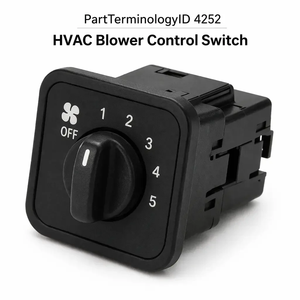
PartTerminologyID 4252, HVAC Blower Control Switch, is the driver-operated control input device mounted in the instrument panel or center stack that accepts the occupant's blower speed command and transmits that command to the blower motor resistor pack, the blower motor control module, or the HVAC control module depending on the vehicle's climate control architecture, allowing the occupant to select from a discrete set of blower speed steps or a continuously variable blower speed range to regulate the volume of conditioned or unconditioned air delivered through the cabin duct system. That definition covers the occupant input function correctly and leaves unresolved every question that determines whether the replacement switch produces the correct resistance output or digital signal for each speed step commanded on the vehicle's specific blower control architecture, whether the switch connector pin count and terminal assignment match the harness connector at the mounting position, whether the physical switch body profile and mounting tab geometry allow installation in the instrument panel cutout without gaps or interference at the panel bezel, whether the switch covers the same number of blower speed steps as the original so that the highest commanded step delivers full voltage to the blower motor, whether the switch is a rotary type or a sliding type or a rocker type or a push-button array type that matches the original control interface in the panel, whether the replacement is compatible with a manual climate control system or an automatic climate control system where the blower speed is modulated by a separate HVAC control module rather than directly by the switch output, whether the switch includes an integrated illumination lamp or LED element for night visibility and whether the illumination circuit voltage and bulb base type match the original, whether the replacement covers a single-zone system or a dual-zone system where the driver and passenger blower speeds are controlled independently, and whether the vehicle's blower circuit uses a resistor pack downstream of the switch or a pulse-width-modulated blower motor control module that requires a different signal type from the switch than a resistor-based circuit does.
It does not specify the control architecture compatibility, connector pin count, terminal assignment, switch body profile, speed step count, switch type, climate control system type, illumination circuit, zone configuration, or downstream circuit type. A listing under PartTerminologyID 4252 that states only year, make, and model without control interface type and speed step count cannot be evaluated by a technician replacing a failed rotary blower switch on a vehicle where the same model year was produced with both a five-speed rotary manual switch for the base climate package and a three-speed rocker switch for the fleet trim level, because the connector pin counts differ between the two switch types and the resistor pack downstream of the fleet switch is calibrated for three speed steps rather than five.
For sellers, PartTerminologyID 4252 is the HVAC control PartTerminologyID where the widest range of within-model-year variation produces the highest listing complexity of any single climate control component. The blower switch sits at the interface between the occupant and the blower circuit, but the nature of that interface varies across manual resistor-based systems, electronically controlled manual systems, and fully automatic climate control systems in a way that makes a year-make-model fitment claim insufficient to confirm compatibility without the control architecture attribute. A switch that fits the mounting cutout and mates with the harness connector but produces the wrong resistance value at the second speed step will deliver a blower speed that does not match the labeled position, which the owner will interpret as a failed replacement rather than a mismatch, and the switch will be returned.
What the HVAC Blower Control Switch Does
Blower Speed Control Architectures and Why They Require Different Switch Output Types
The HVAC blower control switch operates within one of three circuit architectures depending on the vehicle's climate system design, and the switch output type required by each architecture differs fundamentally. Understanding which architecture is present determines whether the correct replacement is a resistive switch, a potentiometer-type switch, or a digital signal switch, and a replacement that produces the wrong output type for the architecture will either operate incorrectly on every speed step or fail to communicate with the control module entirely.
The first architecture is the direct resistor pack system used in manual climate control vehicles. In this system, the blower switch connects battery voltage (or a fused blower circuit supply) to one of several taps on a blower motor resistor pack mounted in the duct system, with each tap presenting a different series resistance in the blower motor circuit and therefore delivering a different motor voltage and blower speed. The switch does not modulate the blower motor voltage directly. It selects which resistor pack tap is active by routing the circuit through the selected resistance element. The highest speed setting bypasses the resistor pack entirely and delivers full supply voltage to the motor. In this architecture, the switch's function is purely a multi-position selector and it carries the full blower motor current on every speed step except the highest, where it carries only the bypass current. The switch contacts must be rated for the blower motor's steady-state operating current, which ranges from 8 to 20 amperes depending on motor size and speed.
The second architecture is the blower motor control module system used in many vehicles from the mid-1990s onward. In this system, the blower switch does not carry the blower motor current directly. Instead, it sends a low-current signal (either a variable resistance or a variable voltage) to a blower motor control module that interprets the signal and drives the blower motor through a power transistor or MOSFET output stage. The switch in this architecture carries only milliampere-level signal current rather than the full motor current, which means the switch contacts are not subject to the arc erosion associated with switching high current loads. The replacement switch must produce the signal output type and signal range that the control module expects. A switch producing a 0 to 5 volt analog output in a system expecting a 500 to 4500 ohm variable resistance input will saturate the module's input stage on every speed setting.
The third architecture is the automatic climate control system where the blower speed is managed by the HVAC control module as part of a closed-loop climate regulation strategy. In this architecture, the blower switch (or blower speed input on the climate control panel) sends a digital command to the HVAC control module via a serial communication bus (LIN bus or a proprietary vehicle network), and the module determines the actual blower motor drive level based on the commanded input, the cabin temperature sensor reading, the evaporator temperature, and the ambient temperature. The switch itself is a digital input device and carries no power circuit current of any kind. A replacement that produces an analog resistance output in a system expecting a digital bus command will not be recognized by the HVAC control module at any speed setting.
Speed Step Count and the Resistor Pack Calibration Dependency
The number of blower speed steps the switch provides must match the number of resistance taps on the resistor pack downstream of the switch in a direct resistor pack system. A five-speed switch routes the circuit through one of four resistor pack taps (with the fifth position bypassing the pack entirely for full speed), and the resistor pack has four resistance elements calibrated to produce the blower speed increments for positions one through four. A three-speed switch routes through two resistor pack taps. If a five-speed switch replaces a three-speed switch on a vehicle with a three-tap resistor pack, positions four and five on the new switch route to resistor pack taps that do not exist, delivering either an open circuit or an incorrect resistance, and positions one and two on the new switch may route to the wrong taps, producing inverted or non-sequential speed progression. The speed step count must match the resistor pack exactly in any direct resistor pack system.
In a blower motor control module system, the speed step count determines the signal output range divisions. A module calibrated for a six-step switch input will interpret the signal from a four-step switch as commanding only the bottom four of its six available speed levels, leaving the upper two drive levels of the motor permanently inaccessible regardless of switch position. The buyer who replaces a six-step switch with a four-step switch will find that the blower never reaches the full speed available on the original system, which will be interpreted as a failed motor or a failed replacement switch rather than a step count mismatch.
Switch Type, Panel Cutout Profile, and the Illumination Circuit
The physical switch type (rotary, sliding, rocker, or push-button array) determines both the panel cutout geometry required for installation and the occupant interaction method. A rotary switch requires a round or D-shaped cutout and uses a knob that rotates through the speed range. A sliding switch requires a rectangular slot and uses a lever that moves linearly. A rocker switch requires a rectangular cutout and uses a self-returning or latching rocker actuator. A push-button array uses individual round or rectangular cutouts or a single integrated panel aperture for the button array. None of these switch types is physically interchangeable with the others at the panel mounting position without modifying the instrument panel cutout, which is not an acceptable repair procedure on a production vehicle.
The switch illumination circuit is a secondary but frequently overlooked attribute. Most blower switches include a small incandescent lamp or LED element behind the speed position markings or the switch panel face that illuminates the switch for night visibility. The illumination element is powered from the instrument lighting circuit, which operates at full battery voltage on some vehicles and at a reduced voltage (typically 5 to 7 volts) on vehicles with a separate panel illumination supply. A replacement switch with an LED illumination element designed for full battery voltage will produce full-brightness illumination regardless of the instrument dimmer setting on a vehicle with a variable-voltage dimmer circuit. A replacement with an incandescent element in a circuit designed for LED current will draw more current than the circuit is rated for and may damage the instrument lighting circuit fuse or the dimmer module.
Dual-Zone Systems and Independent Driver and Passenger Speed Control
Dual-zone automatic climate control systems provide independent blower speed control for the driver side and the passenger side of the cabin. In these systems, the blower speed input is typically a separate rotary encoder or push-button array for each zone, and each input communicates independently with the HVAC control module. A replacement for the driver-side blower speed input must be specified as the driver-side unit. A replacement for the passenger-side input must be specified as the passenger-side unit. On systems where the driver and passenger inputs are integrated into a single control assembly, the entire assembly must be replaced rather than an individual zone input, and the listing must note whether the part covers the complete dual-zone assembly or only one zone's input.
Resistor Pack Compatibility, Contact Arc Erosion, and Why the Wrong Replacement Leaves Speeds Missing
How contact arc erosion at the high-current speed positions fails specific speeds selectively
In a direct resistor pack blower control system, the switch contacts at the lower speed positions carry the highest current because the lower speed positions route the circuit through the resistor pack elements, and the resistor pack elements reduce voltage but do not reduce the current drawn by the motor at those speeds. The motor at low speed draws a lower current than at high speed, which means the lower speed contacts carry less current than the high speed contact, but the difference in current between speed positions is not large enough to exempt the lower speed contacts from arc erosion concern. What differentiates the erosion rate between speed positions is not current magnitude but contact cycling frequency: the low speed position is the most frequently used in stop-and-go urban driving where blower speed adjustments are common, and the contact at that position accumulates the most make-and-break cycles per year of vehicle operation.
Arc erosion at a single speed position contact produces a failed speed at that position while the adjacent positions remain functional. The buyer will describe the symptom as: blower works on high but not on low, or blower works on all speeds except position two. This symptom pattern is specific to contact erosion in a direct resistor pack system and distinguishes the switch failure from a failed resistor pack element (which produces a missing speed even with a new switch). A voltage drop test across each switch position with the blower operating confirms whether the missing speed is caused by high contact resistance in the switch or an open resistor pack element. Replacing the switch without confirming the resistor pack is intact risks returning the same symptom with a new switch if the resistor pack element at the affected speed step is also open.
Why a replacement switch with incorrect contact resistance values produces wrong speeds on every position
In a direct resistor pack system, the switch routes the blower circuit through specific resistor pack taps by connecting specific switch terminals to the resistor pack input wire. The switch contact resistance at each position is negligible relative to the resistor pack element resistance, which means the speed at each position is determined by the resistor pack, not by the switch. In this architecture, a replacement switch that fits and connects correctly will deliver the correct speed at each position regardless of the switch's internal contact resistance, as long as the contact resistance is below the threshold that produces a measurable voltage drop.
In a blower motor control module system, the switch produces a signal (variable resistance or variable voltage) that the module maps to specific blower drive levels. If the replacement switch's signal output values at each step do not match the module's calibration map, the module will deliver a blower speed that does not correspond to the labeled position. A switch producing 2,000 ohms at the third speed position in a system calibrated to expect 1,500 ohms at the third position will command a lower blower speed than the third position label indicates. The buyer will perceive this as the replacement producing incorrect speeds rather than as a calibration mismatch, and the switch will be returned as defective. The listing must confirm that the switch's signal output values match the module's calibration for the specific application.
Contact current rating and the consequence of undersized switch contacts
A replacement blower switch for a direct resistor pack system must have contacts rated for the maximum blower motor current at each speed position. The full-speed position is the highest current position because it bypasses the resistor pack and delivers full supply voltage to the motor. A motor drawing 15 amperes at full speed requires switch contacts rated for at least 15 amperes at the full-speed position. A replacement switch with contacts rated for 10 amperes installed in a 15-ampere circuit will operate without visible failure initially but will experience accelerated contact arc erosion at the full-speed position, because the contact material is ablated more rapidly by arc events at current levels above the contact rating. The contact will fail at the full-speed position within a fraction of the service interval of a correctly rated replacement.
Automatic Climate Control Integration and Why Manual Switch Replacements Do Not Cross Over
The HVAC control module's role in automatic systems and the digital command requirement
In automatic climate control systems, the blower speed input switch is not a standalone blower circuit controller. It is one of several occupant inputs to the HVAC control module, which manages the blower motor, the compressor clutch, the blend doors, and the mode doors as a coordinated system to maintain the cabin temperature set by the occupant. The blower speed command from the switch is one input among several; the module may override the commanded speed upward during maximum cooling or heating demand or downward during cabin temperature stabilization. The switch's role is to communicate the occupant's preference, not to directly control the motor.
This architecture means the replacement switch for an automatic climate control system must be compatible with the vehicle's specific HVAC control module, because the module's input stage is calibrated for the signal type and signal range of the original switch. An aftermarket switch that produces a signal within the correct type and range but with different step values than the original will cause the control module to map the occupant's commands to different blower speeds than intended, producing a climate system that appears to respond to input but does not deliver the commanded comfort level. In some automatic systems, a sufficiently out-of-range switch signal will cause the module to default to a safe operating mode where the blower runs at a fixed mid-range speed regardless of input, which the owner will correctly identify as a failed climate control system caused by the replacement switch installation.
Why a manual switch replacement does not substitute for an automatic climate control blower input
A manual blower switch from the same vehicle platform's base climate trim level cannot substitute for the automatic climate control blower speed input even if the two components share a connector body type and mounting position, because the manual switch produces a direct resistor pack tap selection signal and the automatic system's blower speed input produces a digital or analog module communication signal. Installing a manual switch in an automatic climate control system will connect a resistor tap selector to a module input expecting a digital command, producing no blower response or a constant full-speed response depending on how the module interprets the unexpected signal level.
The listing must explicitly prevent this cross-application by specifying the climate control system type (manual or automatic) as a required attribute and by noting that manual and automatic blower switch types are not interchangeable even on the same platform. The temptation to cross-apply is present in the catalog because the mounting positions and connector bodies are sometimes shared across climate trim levels, and a buyer who sees that a manual switch physically fits the automatic system's mounting position will assume it is compatible.
Why This Part Generates Returns
Buyers return HVAC blower control switches because the replacement is a five-speed rotary and the vehicle has a three-speed rocker, with different connector pin counts that prevent the harness connector from mating; the switch is specified for manual climate control and installs in an automatic climate control system where the module expects a digital bus command rather than a resistor tap selector output, producing no blower response on any switch position; the speed step count is four and the resistor pack downstream has five taps, leaving the fifth speed permanently inaccessible; the illumination element is an LED rated for full battery voltage and the instrument lighting circuit uses a reduced-voltage supply, producing full-brightness illumination that does not respond to the dimmer control; the switch body profile is correct but the knob spline is a different count than the original, preventing the original knob from seating; the replacement is a single-zone switch and the vehicle has a dual-zone system where the driver-side and passenger-side inputs are integrated in a single assembly; the contact current rating is 10 amperes and the blower motor draws 14 amperes at full speed, producing accelerated contact erosion at the full-speed position within three months; the switch produces a variable resistance output and the blower motor control module expects a variable voltage output, saturating the module input stage on every position; and the replacement does not include the mounting clip or bezel tab hardware that retains the switch in the instrument panel cutout, leaving the switch loose in the panel after installation.
Top Return Scenarios
Scenario 1: "Five-speed rotary delivered for three-speed rocker application, connector pin counts do not match"
The buyer's three-speed rocker blower switch has a cracked actuator that prevents position three from latching. The listing covers the vehicle by year and model without specifying switch type. The delivered unit is a five-speed rotary switch from the higher climate trim level on the same platform. The five-speed switch uses a six-pin connector; the three-speed rocker uses a four-pin connector. The harness connector at the mounting position has four pins. The six-pin replacement connector cannot mate with the four-pin harness connector. The original three-speed rocker had a different pin assignment than the five-speed rotary even if connector body compatibility had existed.
Prevention language: "Switch type: [rotary / sliding / rocker / push-button array]. Speed step count: [X] steps. Connector pin count: [X] pins. This listing covers the [switch type] with [X]-pin connector. Verify switch type and connector pin count against the original. Rotary, rocker, and push-button switch types are not interchangeable at the panel mounting position and use different connector configurations even on the same platform."
Scenario 2: "Manual switch installed in automatic climate control system, no blower response on any position"
The buyer's automatic climate control blower speed input is unresponsive on positions one and two, responding only on position three (full speed). The buyer sources a blower switch listing by year and model without confirming climate system type. The delivered switch is the manual climate control rotary switch from the base trim. The manual switch produces a resistor tap selector output. The automatic climate control module expects a LIN bus digital command. After installation, the module receives a signal it does not recognize and defaults to a safe mode with the blower off. The vehicle has no blower function at any switch position.
Prevention language: "Climate control system type: [manual resistor-based / manual with blower motor control module / automatic climate control]. This switch is specified for [climate system type]. Manual and automatic climate control blower switches are not interchangeable. An automatic climate control system requires a switch that produces the digital or analog signal expected by the HVAC control module. A manual resistor-tap switch in an automatic system will produce no blower response or a fixed default speed."
Scenario 3: "Four-step switch installed on five-tap resistor pack, full speed position bypassed"
The buyer replaces the blower switch on a vehicle with a five-tap resistor pack. The listing covers the speed range as multi-speed without specifying step count. The delivered switch has four speed positions. Positions one through three route to resistor pack taps one through three correctly. Position four on the new switch, intended as the full-bypass high-speed position, connects to resistor pack tap four rather than the bypass line, because the switch's internal circuit routes position four to the fourth terminal pin and the harness connects that pin to tap four rather than bypass. The blower runs at an intermediate speed on position four and never reaches full speed. The buyer cannot access the full blower output on the hottest summer day.
Prevention language: "Speed step count: [X] steps matching [X]-tap resistor pack. Verify the resistor pack tap count before ordering. A switch with fewer steps than the resistor pack has taps will fail to route the full-bypass high-speed circuit correctly, preventing the blower from reaching full speed at any switch position."
Scenario 4: "Full-voltage LED illumination in reduced-voltage dimmer circuit, switch face at full brightness regardless of dimmer position"
The buyer's original switch has a burned-out illumination lamp. The replacement switch uses an LED illumination element designed for the 12-volt instrument lighting circuit. The vehicle's instrument lighting system uses a 5-volt supply rail for the panel illumination with a PWM dimmer. The LED element in the replacement switch is not designed for the PWM dimmer signal on the 5-volt supply and illuminates at a fixed brightness that does not vary with the dimmer control input. The buyer reports the switch face is excessively bright at night and the dimmer has no effect on the blower switch.
Prevention language: "Illumination type: [incandescent lamp, specify voltage and base type / LED, specify supply voltage compatibility]. Verify the instrument lighting circuit supply voltage and dimmer type before ordering. An LED illumination element designed for full battery voltage will not respond to a PWM dimmer on a reduced-voltage instrument lighting supply."
Scenario 5: "Switch body correct, knob spline count does not match original, knob cannot be transferred"
The buyer replaces the switch body on a rotary blower switch. The replacement switch body has the correct panel cutout profile and connector pin count. The original knob is retained for transfer to the new body. The original knob has a six-spline bore and the replacement switch shaft has an eight-spline profile. The knob cannot be seated on the new shaft. The buyer cannot operate the replacement switch without sourcing a new knob separately, which is not included in the listing and is not available as a standalone part from the seller.
Prevention language: "Knob interface: [X]-spline shaft, knob [included / not included, transfer original]. If the original knob is to be transferred, verify the knob spline count matches before ordering. Spline counts differ between switch generations on the same platform. A knob with the wrong spline count cannot be seated on the replacement shaft."
Scenario 6: "Single-zone switch installed in dual-zone system, passenger-side speed input non-functional"
The buyer's dual-zone automatic climate control system has a failed blower speed input on the driver side. The listing covers the vehicle by year and model. The delivered switch is the single-zone version from the base single-zone climate trim. The dual-zone system uses an integrated assembly where the driver-side and passenger-side speed inputs share a single connector and a single circuit board. The single-zone switch covers only the driver-side input. After installation, the driver-side input responds but the passenger-side input connector is unoccupied, leaving the passenger-side blower speed control non-functional and defaulting to the last stored module value.
Prevention language: "Zone configuration: [single-zone / dual-zone integrated assembly]. This switch covers [single-zone / dual-zone] operation. Dual-zone climate control systems require the dual-zone integrated assembly where driver-side and passenger-side speed inputs are combined in a single unit. A single-zone switch in a dual-zone system leaves the passenger-side input unconnected."
Scenario 7: "Variable resistance switch output, module expects variable voltage input, module input saturated on all positions"
The buyer's blower motor control module system has a switch that produces no signal on positions two and three. The listing covers the vehicle without specifying signal output type. The delivered switch produces a variable resistance output (0 to 1000 ohms across the speed range). The blower motor control module on this application expects a variable voltage input (0.5 to 4.5 volts) from a potentiometer-type switch powered by the module's 5-volt reference output. The variable resistance switch presents near-zero ohms to the module's reference output at the low-speed position, pulling the reference line to ground and saturating the module's analog-to-digital input stage. The blower motor runs at full speed regardless of switch position.
Prevention language: "Switch signal output type: [variable resistance, specify range in ohms / variable voltage, specify range in volts / digital bus command, specify protocol]. Verify the signal output type against the blower motor control module's input specification. A variable resistance output switch in a system expecting variable voltage input will saturate the module input stage and produce a fixed full-speed output regardless of switch position."
Scenario 8: "Contact current rating insufficient for full-speed bypass position, arc erosion at full-speed contact within three months"
The buyer installs the replacement switch. All speed positions operate correctly at installation. After ninety days of normal use, the full-speed position becomes intermittent: the blower drops to the next lower speed position momentarily before recovering, and after thirty additional days the full-speed position fails entirely while all lower positions remain functional. Inspection of the failed switch shows severe arc erosion at the full-speed bypass contact. The blower motor draws 16 amperes at full speed on this application. The replacement switch contacts are rated for 12 amperes.
Prevention language: "Contact current rating: [X] amperes at full-speed bypass position. Verify the blower motor's full-speed current draw before ordering. The full-speed bypass position carries the highest current in the circuit and requires a contact rating equal to or greater than the motor's full-speed operating current. An undersized contact rating produces accelerated arc erosion at the full-speed position, which is the first position to fail."
Core Listing Attributes for PartTerminologyID 4252
PartTerminologyID: 4252
Component: HVAC Blower Control Switch
Climate control system type: manual resistor-based, manual with blower motor control module, or automatic climate control (mandatory, in title)
Switch type: rotary, sliding, rocker, or push-button array (mandatory, in title)
Speed step count: number of discrete positions (mandatory)
Connector pin count and terminal assignment (mandatory)
Switch signal output type: resistor tap selector, variable resistance with range in ohms, variable voltage with range in volts, or digital bus command with protocol (mandatory)
Contact current rating in amperes at full-speed bypass position (mandatory for resistor-based systems)
Blower motor control module compatibility note for module-based systems (mandatory)
Zone configuration: single-zone or dual-zone (mandatory)
Illumination type: incandescent with voltage and base type, or LED with supply voltage compatibility (mandatory)
Knob interface: spline count, and whether knob is included or must be transferred (mandatory for rotary switches)
Panel mounting hardware: clips, bezel tabs, or screws, and whether included in kit (mandatory)
Switch body profile dimensions for panel cutout verification (recommended)
Year/make/model/submodel/trim
Note for trim levels with different climate control system types on the same platform
Note for production date range where switch type or step count changed mid-year
Note for engine or drivetrain variants with different blower motor current draws affecting contact rating requirement
Note for dual-zone applications requiring integrated assembly versus individual zone input
Catalog Checklist for ACES/PIES Teams
PartTerminologyID = 4252
Require climate control system type in title (mandatory)
Require switch type in title (mandatory)
Require speed step count in listing (mandatory)
Require connector pin count and terminal assignment (mandatory)
Require switch signal output type with range or protocol (mandatory)
Require contact current rating at full-speed bypass position for resistor-based systems (mandatory)
Require zone configuration: single-zone or dual-zone (mandatory)
Require illumination type with supply voltage and dimmer compatibility (mandatory)
Require knob interface spline count and knob inclusion status for rotary switches (mandatory)
Require panel mounting hardware content (mandatory)
Prevent climate system type omission: a manual resistor-tap switch in an automatic climate control system produces no blower response or a fixed default speed; climate system type must be in every listing without exception
Prevent switch type omission: rotary, rocker, sliding, and push-button switches use different panel cutouts and different connector configurations; switch type must be stated in the title for every listing
Prevent speed step count omission: a switch with fewer steps than the resistor pack has taps leaves the full-bypass high-speed position inaccessible; step count must be verified against resistor pack tap count before ordering
Prevent signal output type omission: a variable resistance switch in a variable voltage module input system saturates the module input stage; signal output type must be stated and verified against the module's input specification
Prevent contact current rating omission: an undersized contact rating at the full-speed bypass position produces arc erosion failure within a fraction of the service interval; current rating must be stated for all resistor-based system listings
Prevent illumination voltage omission: an LED element rated for full battery voltage in a reduced-voltage dimmer circuit operates at fixed brightness with no dimmer response; illumination supply voltage compatibility must be stated
Prevent knob spline omission: a spline count mismatch prevents knob transfer and leaves the switch inoperable; spline count must be stated for all rotary switch listings
Prevent single-zone and dual-zone conflation: a single-zone switch in a dual-zone system leaves the passenger-side input unconnected; zone configuration must be confirmed before ordering on platforms where both configurations were produced
Differentiate from HVAC Blower Motor Resistor (PartTerminologyID 4248 or similar): the resistor pack is the downstream component that sets the blower speed for each switch position in a resistor-based system; a missing speed caused by an open resistor pack element will recur with a new switch if the resistor pack is not also replaced; confirm which component is failed before ordering the switch
Differentiate from HVAC Control Panel (PartTerminologyID 4246 or similar): the full control panel assembly integrates the blower switch, temperature control, mode selector, and in some applications the display into a single unit; if the blower switch failure is caused by a failed control board within the panel rather than a failed switch actuator, the full panel assembly may be required rather than the individual switch
Differentiate from Blower Motor Control Module (PartTerminologyID 4251 or similar): the control module is the downstream power driver that the switch signals in a module-based system; an unresponsive blower after switch replacement in a module-based system may indicate a failed module rather than a failed switch; confirm module function before concluding the switch replacement was ineffective
FAQ (Buyer Language)
How do I know which type of blower control switch my vehicle uses?
The quickest method is to count the connector pins on the harness connector at the switch mounting position and compare to the listing. A two or three-pin connector in a simple circuit indicates a direct resistor-tap switch. A four or five-pin connector with a low-current harness wire gauge (18 to 22 AWG throughout) indicates a blower motor control module system where the switch carries only signal current. A connector with mixed wire gauges (one or two heavier wires alongside lighter signal wires) indicates a hybrid circuit. Confirming the climate system type (manual or automatic) from the vehicle's window sticker or build data eliminates the primary source of mismatch before ordering.
Why does my blower work on some speeds but not others?
A missing speed that is specific to one or two positions while the others work correctly is either a failed switch contact at that position (in a direct resistor-based system) or a failed resistor pack element at the corresponding tap (also in a direct resistor-based system). A voltage drop test across the switch contacts at the failing position distinguishes the two: high contact resistance at the failing position points to the switch; normal contact resistance with an open circuit downstream points to the resistor pack. Both components should be inspected before ordering either replacement.
Can I use a higher step count switch to get more blower speeds?
No, not in a direct resistor-based system. The switch step count must match the resistor pack tap count. Adding switch positions that route to non-existent resistor pack taps produces open circuits or incorrect circuit paths at those positions. In a blower motor control module system, the module's calibration determines how many drive levels are available regardless of switch step count. A switch with more steps than the module is calibrated for will produce repeated or skipped speed levels at the additional positions.
My blower runs at full speed after I installed the new switch. What happened?
A blower that runs at full speed on every switch position regardless of the commanded level is the characteristic symptom of a signal mismatch in a blower motor control module system. The module's input is receiving a signal it interprets as maximum speed command, typically because the switch is pulling the module's reference line to ground or producing a voltage that the module maps to its maximum drive level. Verify that the replacement switch's signal output type and range match the module's input specification. A variable resistance switch in a variable voltage input system or a grounded signal line in any module-based system will produce this symptom.
Do I need to replace the blower motor resistor pack at the same time as the switch?
Not necessarily, but it is worth inspecting. If the missing speed that prompted the switch replacement also produces a symptom on the new switch, the resistor pack element at that speed tap is likely also open. Since the resistor pack is exposed to airflow-borne debris and moisture in the duct system and has the same service age as the failed switch, replacing both components during the same service event eliminates the risk of a return visit for the resistor pack within the same service interval.
Why does the dimmer not affect my new switch's illumination?
The illumination element in the replacement switch is most likely an LED rated for full battery voltage operating in a vehicle with a reduced-voltage or PWM instrument lighting circuit. The LED illuminates at its rated brightness regardless of the dimmer setting because it is either above the minimum LED threshold voltage at all dimmer positions or is not responsive to the PWM frequency used by the dimmer. Confirm the instrument lighting circuit supply voltage and dimmer type before selecting the replacement, and specify an illumination element compatible with the vehicle's dimmer architecture.
Related PartTerminologyIDs
HVAC Blower Motor Resistor (PartTerminologyID 4248 or similar): the resistor pack downstream of the switch in a direct resistor-based system that sets the motor voltage for each speed step; a failed resistor pack element produces a missing speed symptom identical to a failed switch contact; confirm which component is at fault before ordering; replacing both during the same service event is recommended when either has failed
Blower Motor Control Module (PartTerminologyID 4251 or similar): the power driver module that the switch signals in a module-based system; a module that defaults to fixed full speed or zero speed after switch replacement indicates a module failure rather than a switch failure; confirm module function with a known-good switch signal before concluding the module requires replacement
HVAC Control Panel Assembly (PartTerminologyID 4246 or similar): the full integrated panel that may include the blower switch, temperature control, and mode selector as a single unit; appropriate when the blower switch failure is caused by a failed circuit board within the panel rather than a mechanically failed switch actuator
Blower Motor (PartTerminologyID 4247 or similar): the motor whose speed is controlled by this switch; a motor that draws above-rated current at full speed will accelerate contact arc erosion in a direct resistor-based switch; confirm the motor's current draw is within specification before attributing a repeated switch failure to switch quality
HVAC Blower Motor Resistor Wire Harness (if cataloged separately): the pigtail connecting the resistor pack to the vehicle harness; a burned or corroded resistor pack pigtail connector produces the same missing-speed symptom as a failed switch or resistor pack element and should be inspected when the harness connector at the resistor pack shows heat discoloration
Status in New Databases
PIES/PCdb: PartTerminologyID 4252, HVAC Blower Control Switch
PIES 8.0 / PCdb 2.0: No change in PartTerminologyID or terminology label
Final Take for PartTerminologyID 4252
HVAC Blower Control Switch (PartTerminologyID 4252) is the climate control PartTerminologyID with the widest within-platform variation of any single HVAC input component, because the same vehicle model year may be produced with manual resistor-based switches, manual module-based switches, and automatic climate control inputs that differ in signal output type, connector pin count, speed step count, and physical switch type, and none of these variants is interchangeable with the others despite sharing a mounting position and sometimes a connector body. The technician replacing a failed rotary switch needs the speed step count and signal output type to avoid installing a five-step switch on a three-tap resistor pack or a resistor-tap selector in a module-input circuit. The shop working on an automatic climate control system needs the climate system type attribute to avoid installing a manual switch that produces no response from the HVAC control module. The buyer in a dual-zone vehicle needs the zone configuration attribute to avoid installing a single-zone switch that leaves the passenger-side input permanently unconnected.
State the climate control system type in the title. State the switch type in the title. State the speed step count. State the connector pin count and terminal assignment. State the signal output type with range. State the contact current rating for resistor-based systems. State the illumination type and supply voltage compatibility. State the knob spline count for rotary switches. State the zone configuration. For PartTerminologyID 4252, climate control system type, speed step count matching the resistor pack tap count, and signal output type are the three attributes beyond the standard fitment checklist that prevent the three most costly and least obvious return scenarios in the HVAC blower control switch buyer population.