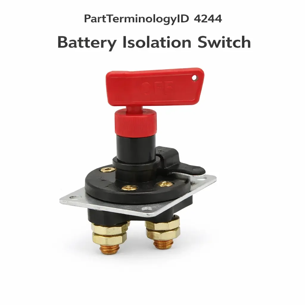
Battery Isolation Switch (PartTerminologyID 4244): Where Current Rating and Installation Position Prevent Switch Failure and Electrical System Damage
Written by Arthur Simitian | PartsAdvisory
PartTerminologyID 4244, Battery Isolation Switch, is the manually operated switch that disconnects the vehicle battery from the electrical system to prevent parasitic current drain during extended storage, to isolate the electrical system for maintenance and safety during servicing, to prevent battery discharge from alarm or accessory system faults, or to meet motorsport and emergency vehicle safety regulations that require a remotely or manually operable main power disconnect for rapid electrical system shutdown in the event of a fire or collision. That definition covers the battery isolation switch function correctly and leaves unresolved whether the switch is a simple rotary knob that the operator turns manually to disconnect the battery, a key-operated disconnect switch that requires a removable key to operate and serves as a theft deterrent in addition to an isolation function, a remote-operated solenoid disconnect that allows electrical isolation from a remote location such as the driver's cockpit in a race vehicle, a stud-type disconnect post that accepts a removable cable terminal as the switching element, whether the switch is designed to handle the full starting current of the vehicle electrical system including engine cranking current or is rated only for standby current loads without cranking current capacity, the battery terminal type the switch accepts including SAE post, JIS post, or stud terminal, the continuous current rating and the cranking current rating that the switch must meet for the application, and whether the switch is installed on the battery positive cable, the battery negative cable, or both cables simultaneously on a dual-pole isolation application.
For sellers, PartTerminologyID 4244 is the battery isolation switch where current rating selection is the most return-generating attribute, because a switch installed in a vehicle's main battery circuit must handle not only the continuous current of the vehicle's accessory and ignition loads but also the high cranking current surge when the engine is started. A switch rated for 100 amperes continuous current is inadequate for a cranking current surge of 400 to 600 amperes on a V8 gasoline engine and will experience contact arc damage and internal resistance increase on every engine start. A buyer who installs an undersized switch and finds it fails or causes hard starts within weeks of installation will return it as defective when the current rating mismatch was the fault.
What the Battery Isolation Switch Does
Continuous current rating versus cranking current rating and the selection requirement
Battery isolation switches must be rated for two distinct current conditions. The continuous current rating specifies the maximum sustained current the switch contacts can carry without overheating during normal vehicle operation. The cranking current rating specifies the maximum peak current the switch contacts can withstand during the engine start event without arc welding the contacts or producing excessive voltage drop that prevents cranking.
A vehicle with a V8 gasoline engine draws 300 to 600 amperes during engine cranking, depending on engine displacement, ambient temperature, and battery condition. An isolation switch with a continuous current rating of 100 amperes but no cranking current rating, or with a cranking current rating of only 200 amperes, will experience contact arc damage during every engine start. The arc energy from the 400-ampere surge contacting the switch contacts will pit and erode the contact surfaces over repeated start cycles, progressively increasing contact resistance until the switch produces a voltage drop that causes hard starts or the switch contact welds and cannot be opened.
High-performance and diesel engine applications have even higher cranking current demands. A large diesel engine may draw 800 to 1000 amperes during cold-weather cranking. Race vehicle battery isolation switches must handle not only normal cranking current but also the momentary current surge from high-power ignition and fuel injection systems. The switch current ratings must exceed the highest current demand in the specific application, not simply the continuous load current.
Positive cable versus negative cable installation and the system architecture consideration
Battery isolation switches are most commonly installed in the positive battery cable between the battery positive terminal and the vehicle wiring harness connection point. Positive cable installation is the standard configuration for most consumer vehicle storage and maintenance isolation applications. Disconnecting the positive cable isolates the vehicle electrical system from the battery supply while leaving the battery negative cable connected to the vehicle chassis ground.
Some motorsport and safety applications require the isolation switch to be installed in the negative cable or as a dual-pole switch that simultaneously disconnects both positive and negative cables. Negative cable isolation is preferred in some applications because it isolates the chassis ground return path, which prevents current flow through any ground-referenced parasitic path even if the positive cable has a wiring fault that creates an unintended ground connection to the chassis.
Installing a positive cable switch in the negative cable or a negative cable switch in the positive cable does not produce immediate failure but may not meet the intended safety or regulatory requirement for the application. Motorsport series regulations specify which cable or cables must be interrupted and whether a dual-pole switch is required. Installing the switch in the specified position is mandatory for regulatory compliance.
Key-operated switch as theft deterrent and the key storage consideration
Key-operated battery isolation switches serve two functions simultaneously: they isolate the battery for storage or maintenance and they prevent unauthorized vehicle operation by requiring the key to be inserted before the battery circuit is completed. The key is typically stored away from the vehicle when the isolation function is active, making the vehicle inoperable without the key.
A buyer who installs a key-operated switch and then loses or misplaces the removal key has an isolated battery and a vehicle that cannot be operated until the key is recovered or a locksmith service is engaged. This is not a switch fault but is a common scenario that generates a return when the buyer cannot locate the key and concludes the switch is defective. The listing must note the key retention requirement for key-operated switches.
Why This Part Generates Returns
Buyers return battery isolation switches because the switch current rating is insufficient for the cranking current demand and the switch fails from repeated contact arc damage, the switch is installed in a position that does not meet the regulatory requirement for the motorsport or safety application, the key-operated switch key is lost and the vehicle is inoperable rather than accessible for key recovery service, the switch contact resistance after installation produces a voltage drop that causes intermittent cranking or hard starts on a correctly rated switch that was not installed with fully clean terminal contacts, and the switch is incompatible with the battery terminal type on the vehicle and the connection cannot be made with the correct torque.
Status in New Databases
PartTerminologyID 4244 is cataloged in PIES/PCdb as Battery Isolation Switch. Under PIES 8.0 and PCdb 2.0 there is no change to the terminology or classification for this PartTerminologyID.
Top Return Scenarios
Scenario 1: "Switch current rating insufficient for cranking current, contact arc damage within weeks"
The buyer installs a 100-ampere continuous rated isolation switch in the positive cable of a V8 truck. The switch's cranking current specification is not clearly stated in the listing. The engine cranking current draws 450 amperes on cold starts. The switch contacts experience significant arc erosion on every cold start. Within weeks the contact resistance has increased to a level that produces a 0.4-volt drop during cranking, causing the starter motor to receive insufficient voltage for consistent cold cranking. The buyer returns the switch as failing.
Prevention language: "Cranking current rating: Confirm the switch cranking current rating meets or exceeds the maximum cranking current demand for your specific engine. V8 gasoline engines draw 300 to 600 amperes during cold cranking. Diesel engines draw 600 to 1000 amperes. A switch rated only for continuous current without a specified cranking current rating is not appropriate for any application where the engine is started through the switch. Select a switch with a cranking current rating that exceeds your engine's maximum cold cranking amperage."
Scenario 2: "Contact resistance from improper terminal installation, voltage drop causes hard starts"
The buyer installs the isolation switch but does not fully clean the battery terminal and cable lug contact surfaces before tightening the switch terminals. Oxidation on the battery post and cable lug produces a resistance layer between the terminal and the switch contact surface. The voltage drop across the oxidized interface during cranking reduces starting current by 15 percent. The engine cranks slowly on cold mornings. The buyer returns the switch as causing hard starts.
Prevention language: "Terminal preparation: Before installing the isolation switch, clean the battery post and cable lug contact surfaces with a wire brush or battery terminal cleaner to remove oxidation. A resistance layer from oxidized terminal surfaces between the battery post and the switch contact produces a voltage drop that reduces cranking current independently of the switch's own contact resistance. Install the switch terminals to the specified torque on clean surfaces for minimum contact resistance."
Scenario 3: "Key lost, vehicle inoperable, switch returned as defective"
The buyer installs a key-operated isolation switch and places the isolation key in a location that is later forgotten. The vehicle cannot be operated without the key. The buyer returns the switch as defective when the isolation function is performing exactly as designed.
Prevention language: "Key retention: Keep the isolation switch key in a secure location where it can be retrieved when the vehicle needs to be operated. The vehicle cannot be started when the key is removed and the switch is in the isolation position. Store the key in a known location accessible to authorized users. Do not store the key in the vehicle if the theft deterrent function is the primary use of the key-operated design."
Scenario 4: "Positive cable switch installed in negative cable of motorsport application, does not meet regulations"
The buyer purchases a positive cable-rated isolation switch for a race vehicle application and installs it in the negative cable because the negative cable routing is more accessible from the required cockpit switch location. The technical regulations for the series require a dual-pole switch or a positive cable installation specifically. The switch fails technical inspection. The buyer returns it as incorrect for the application.
Prevention language: "Regulatory installation requirement: Motorsport and safety applications may specify which cable must be interrupted by the isolation switch. Confirm the installation position requirement for your specific regulatory series before ordering. Some regulations require positive cable installation, negative cable installation, or a dual-pole switch that interrupts both cables simultaneously. Installing the switch in the non-specified cable position may not meet the regulatory requirement."
Scenario 5: "Switch terminal incompatible with battery post type, connection cannot be made correctly"
The buyer's vehicle has JIS battery posts common on Japanese-specification vehicles. The isolation switch is designed for SAE post dimensions and does not fit the smaller diameter JIS post correctly. The switch terminal loosens under vibration from the incorrect fit. The buyer returns the switch as incompatible with the battery.
Prevention language: "Battery terminal type: Confirm the battery post type on your vehicle before ordering. SAE posts are the standard domestic and European specification with a larger diameter. JIS posts are common on Japanese-specification vehicles with a slightly smaller diameter. A switch designed for SAE posts will not fit JIS posts correctly and may loosen under vibration. Confirm the switch terminal matches the battery post type on your specific vehicle."
Listing Requirements
PartTerminologyID: 4244
Switch type: rotary manual, key-operated, or remote solenoid (mandatory)
Continuous current rating (mandatory)
Cranking current rating (mandatory)
Battery terminal type compatibility: SAE, JIS, or stud (mandatory)
Installation position: positive cable, negative cable, or dual-pole (mandatory)
Regulatory compliance note for motorsport or safety applications where applicable (mandatory)
Cranking current rating selection note (mandatory)
Terminal preparation note (mandatory)
Key retention note for key-operated switches (mandatory)
OEM part number cross-reference where applicable (mandatory)
Catalog Checklist for ACES/PIES Teams
PartTerminologyID = 4244
Require switch type (mandatory)
Require continuous and cranking current ratings (mandatory)
Require battery terminal type compatibility (mandatory)
Require installation position (mandatory)
Prevent undersized cranking current return: cranking current rating must be confirmed against engine cold cranking demand; continuous-current-only rated switches are not appropriate for engine starting applications
Prevent terminal oxidation hard start return: terminal preparation note is mandatory; oxidized interface produces voltage drop independent of switch quality
Prevent key loss return: key retention guidance is mandatory for key-operated switches
Prevent regulatory non-compliance return: installation position requirement must be confirmed for motorsport and safety applications
FAQ (Buyer Language)
How do I determine the correct current rating for my battery isolation switch?
Find the cold cranking amp rating of your battery in your vehicle owner's manual or on the battery label. A battery with a 600 CCA rating indicates the engine may draw up to 600 amperes during cold starting. Select a switch with a cranking current rating that exceeds this figure. Also confirm the switch continuous current rating exceeds the sum of your vehicle's accessory and ignition loads during normal operation, typically 50 to 150 amperes for most passenger vehicles.
Where should I install the battery isolation switch?
For most storage and maintenance isolation applications, install the switch in the positive battery cable between the battery positive terminal and the vehicle fuse box or starter cable junction. If installing for motorsport compliance, confirm the required installation position in the series technical regulations before installation. Some series specify positive cable installation, negative cable installation, or dual-pole isolation.
Can I install the switch myself?
Yes on most applications with basic hand tools. The switch replaces a section of the existing battery cable or is inserted between the battery post and the existing cable connection. Ensure the vehicle ignition is off and no high-draw accessories are active before disconnecting battery cables. Clean all terminal contact surfaces before tightening the switch connections to the specified torque.
Will a battery isolation switch affect my vehicle's memory functions?
Disconnecting the battery erases radio presets, seat memory positions, and adaptive transmission or engine control module learned values on most vehicles. Some modules require a relearn drive cycle after battery reconnection. A memory saver device plugged into the OBD port or accessory outlet can maintain module memory during battery isolation. Confirm which modules in your vehicle require relearning after battery disconnection before isolating the battery for extended periods.
My switch is getting warm during engine operation. Is this normal?
A switch that becomes noticeably warm during operation indicates either elevated contact resistance from a dirty terminal installation or an undersized switch for the continuous current load. A correctly installed switch with clean terminal contacts and an adequate current rating for the load should not become noticeably warm during normal operation. Remove and reinstall the switch with cleaned terminal surfaces if the switch was recently installed. If warming persists, confirm the switch continuous current rating exceeds the vehicle's normal operating current draw.
What Sellers Get Wrong About PartTerminologyID 4244
The most common error is omitting the cranking current rating. The continuous current rating of an isolation switch is the specification buyers see most prominently in listings, but the cranking current rating is the specification that determines whether the switch survives repeated engine starting. A switch rated at 100 amperes continuous that has no cranking current rating will fail from arc erosion within weeks in any engine starting application. Without the cranking current rating buyers select switches based on continuous current alone and experience premature failure from inadequate contact material for the cranking current surge. The cranking current rating is mandatory for every battery isolation switch listing and must be stated alongside the continuous current rating.
The second error is omitting the terminal preparation note. A switch with correct current ratings installed on oxidized terminal surfaces will produce a voltage drop from the oxidized interface that causes hard starts and that the buyer attributes to switch quality. Without the terminal preparation note buyers return switches as causing hard starts when the oxidized terminal interface was the resistance source.
The third error is omitting the regulatory installation position requirement note for motorsport and safety applications. A significant share of battery isolation switch buyers are installing the switch for motorsport compliance and the regulatory installation position is a mandatory requirement that the switch listing must address. Without the regulatory note buyers install the switch in the most convenient location, fail technical inspection, and return the switch when the installation position was the compliance failure rather than the switch itself.
The fourth error is omitting the key retention note for key-operated switches. A key-operated switch with a lost key leaves the vehicle inoperable. Without the key retention note buyers experience the isolation function as a vehicle immobilization fault and return the switch when the switch is performing exactly as designed.
Cross-Sell Logic
Battery Cable with Integrated Switch Provision: for buyers on applications where the isolation switch is most appropriately installed as part of a new battery cable assembly rather than spliced into the existing cable.
Battery Terminal Cleaner: as a complementary tool recommendation for buyers who need to clean oxidized terminal surfaces before installing the switch to achieve minimum contact resistance.
Memory Saver Device: for buyers who want to maintain vehicle module memory during battery isolation periods, preventing radio preset, seat memory, and adaptive control module relearn requirements after reconnection.
Dual-Pole Isolation Switch: for buyers on motorsport applications where the regulatory requirement specifies simultaneous positive and negative cable isolation through a dual-pole switch rather than a single-pole switch.
Remote Solenoid Disconnect: for buyers on race vehicle or emergency vehicle applications where the isolation switch must be operable from a remote location such as the driver's cockpit or the vehicle exterior.
Why Catalog Data Quality Matters for PartTerminologyID 4244
Battery isolation switch returns cluster around four scenarios that are fully preventable with listing language: cranking current rating insufficiency, terminal oxidation hard starts, key loss immobilization, and regulatory installation position non-compliance. The cranking current rating insufficiency generates the most technically consequential returns because the switch is destroyed by repeated contact arc damage from an undersized rating before it can complete even a single season of service. The terminal oxidation hard start generates returns where the switch is functioning correctly but the installation produced contact resistance from an inadequately prepared terminal surface. The key loss immobilization generates returns where the switch is functioning correctly but the isolation function was inconvenient after key misplacement. The regulatory installation position generates returns from motorsport applications where the switch was installed in the non-specified position.
The cranking current rating specification is the single most important attribute for this PartTerminologyID and its absence from a listing is the most consequential single omission in the entire catalog entry. Every switch sold for engine starting applications must state both the continuous current rating and the cranking current rating. Every listing that omits the cranking current rating exposes buyers to repeated contact arc damage that shortens the switch service life to a fraction of what the correctly sized switch would achieve.
Application Range and Fitment Guidance for PartTerminologyID 4244
Battery isolation switch applications span consumer vehicle storage and maintenance applications, motorsport safety regulations, emergency vehicle electrical shutdown requirements, commercial fleet management applications, marine and RV dual-battery systems, and aftermarket theft deterrent installations. Each application category has different current rating requirements, installation position requirements, and operational requirements that determine the correct switch specification.
Consumer storage applications typically require only a low-current continuous rating for standby load interruption and do not require cranking current capacity if the vehicle is to be stored without starting for extended periods. However, any switch installed in the main battery circuit must be rated for cranking current if the vehicle will ever be started through the switch, because storage switches are often left in place and the vehicle is started with the switch in the connected position.
Motorsport applications are governed by series-specific technical regulations that specify switch type, installation position, activation method, and minimum contact rating. Formula and circuit racing series typically require a dual-pole switch accessible from the driver's cockpit and from outside the vehicle. Rally and off-road series may require the switch to be accessible from specific exterior locations. The listing must be explicit about which motorsport application categories the switch meets and which specific regulation standards it is tested and approved to.
Marine and RV dual-battery applications use isolation switches to select between battery banks and to disconnect individual batteries from the common bus. These applications may require the switch to handle charging current from an alternator in addition to engine starting current, and the alternator current disconnect sequence must be managed correctly to prevent voltage spikes from the inductive energy stored in the alternator field winding.
Final Take for PartTerminologyID 4244
Battery Isolation Switch (PartTerminologyID 4244) is the main power disconnect component where cranking current rating specification, terminal preparation guidance, regulatory installation position disclosure, and key retention guidance are the four attributes that prevent the four most common return scenarios. Every listing without cranking current rating generates arc damage returns from undersized switches in engine starting applications. Every listing without terminal preparation guidance generates voltage drop hard start returns from oxidized terminal interfaces. Every listing without regulatory installation position disclosure generates motorsport technical inspection failure returns from incorrect cable installation. Every listing without key retention guidance generates immobilization returns from lost keys on key-operated switches.
The cranking current rating specification is the single highest-impact attribute for this PartTerminologyID and must be present in every listing where the switch will be used in an application where the engine is started through the switch. Together with the three supporting notes, these four attributes make every listing under this PartTerminologyID complete and give every buyer the specification information needed to select the correct switch and install it correctly for the full designed service life.