HVAC Control Switch (PartTerminologyID 4212): Where Control Module Architecture and Actuator Pre-Check Prevent Switch Replacement
Written by Arthur Simitian | PartsAdvisory
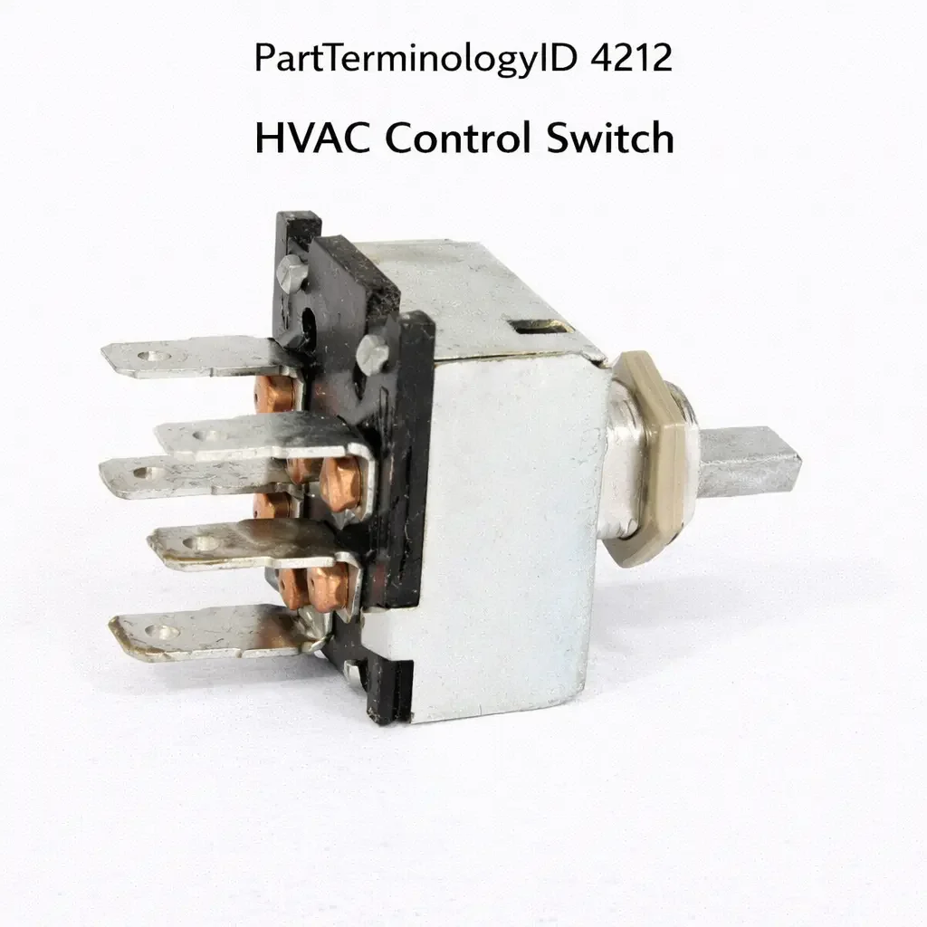
PartTerminologyID 4212, HVAC Control Switch, is the operator interface component through which the driver and passengers select temperature, fan speed, mode, and air distribution settings for the vehicle heating, ventilation, and air conditioning system, transmitting these selections to the HVAC control module, body control module, or directly to the HVAC actuators and blower motor circuit depending on the system architecture. That definition covers the HVAC control switch function correctly and leaves unresolved whether the switch assembly is a discrete single-function switch such as a mode selector switch, a fan speed switch, or a recirculation switch mounted in the instrument panel as an individual component, a multi-function control panel that integrates mode selection, temperature selection, and fan speed adjustment in a single assembly, whether the control switch operates through a direct-wired circuit that sends switched voltage or resistance signals to individual HVAC components, a digital data bus connection through which the switch transmits commands to a climate control module that then manages all HVAC outputs, or a capacitive touch interface on a display screen that is integral to the infotainment system, whether the switch controls a manual HVAC system where all component states are directly determined by switch position or an automatic climate control system where the switch sets a desired temperature and the control module manages actuator positions and blower speed to achieve and maintain that temperature, whether the switch assembly includes illumination bulbs or LED elements for nighttime visibility that may fail independently of the switch contact function, and whether a failed switch produces a system that does not respond to operator input, responds incorrectly to input, or responds correctly but does not produce the expected HVAC output because a downstream actuator or blower motor has failed.
For sellers, PartTerminologyID 4212 is the HVAC control switch where the downstream actuator and blower motor pre-check is the most return-generating attribute, because the HVAC control switch sends commands to downstream components but does not itself produce airflow, temperature change, or mode transitions. A buyer who cannot change the air distribution mode may have a failed mode door actuator rather than a failed switch. A buyer whose blower motor does not change speed may have a failed blower motor resistor rather than a failed switch. A buyer whose temperature does not respond to input may have a failed blend door actuator rather than a failed switch. In all three cases the switch is correctly sending the command to the component and the downstream component is the fault source, but the symptom appears as a non-responsive switch to the buyer.
What the HVAC Control Switch Does
Direct-wired versus data bus switch architecture and the diagnostic difference
Manual HVAC systems use direct-wired control switches where the switch physically completes circuits or changes resistance values that directly control the blower motor speed resistor, the mode door actuator motor supply, and the compressor clutch relay. Testing a direct-wired switch involves confirming that the switch output voltage or resistance changes correctly when the operator moves the switch. A switch that does not change its output when moved has a failed contact set. A switch with correct output that produces no HVAC response has a downstream component fault.
Automatic climate control systems use a climate control module that receives temperature, mode, and fan speed requests from the control switch through a dedicated data bus or direct wired inputs and processes these requests against the cabin temperature sensor, the solar load sensor, and the ambient temperature sensor to determine the required actuator positions and blower speed. The switch on these applications provides the operator's desired settings and the module manages all outputs. A climate control module fault that prevents correct response to switch commands produces the same symptom as a failed switch from the driver's perspective because neither condition produces the expected HVAC output when the switch is adjusted.
Diagnosing a climate control module fault versus a switch fault on automatic climate control systems requires confirming whether the module is receiving the switch input correctly. On most current vehicles the HVAC control switch communicates with the climate control module over a CAN bus or LIN bus, and a scan tool that reads the climate control module inputs can confirm whether the module sees the switch command changing when the operator adjusts the control. If the module registers the switch command but does not produce the expected output, the fault is in the module or downstream. If the module does not register the switch command when the operator adjusts the control, the fault is in the switch or the bus connection between the switch and the module.
Mode door actuator, blend door actuator, and blower motor as downstream fault sources
The HVAC control switch on most systems controls the following downstream components: the mode door actuator that positions the air distribution door to select floor, dash, defrost, and combination modes, the blend door actuator that positions the temperature blend door to mix heated and cooled air to the requested temperature, the recirculation door actuator that selects outside or recirculated air, and the blower motor speed through the blower motor resistor or blower motor control module.
A mode door actuator that has failed in a fixed position will not respond to mode selection commands from the switch. The switch correctly outputs the mode selection command but the actuator cannot execute it. The buyer observes that the air distribution does not change when the mode selector is adjusted and concludes the switch has failed. A blend door actuator that has failed in a fixed position produces a fixed temperature output regardless of temperature selector position. A blower motor resistor that has failed produces only the one fan speed that bypasses the failed resistor element, regardless of fan speed switch position.
All three downstream component faults produce a non-responsive HVAC system symptom that appears at the control switch position but originates downstream. The listing must direct buyers to confirm downstream component function by listening for actuator motor movement when commands are given and by testing blower motor response at all speed positions before diagnosing the control switch.
Illumination fault versus contact fault as separate failure modes
HVAC control switches include illumination elements for nighttime panel backlighting that may fail independently of the switch contact function. A control switch with failed illumination bulbs or LED elements will be unreadable at night but will continue to operate the HVAC system correctly. A buyer who cannot read the control switch at night and interprets the dark panel as a switch failure will return the replacement switch if the illumination fault was the correct diagnosis while the switch contacts remain functional.
Conversely, a switch with functioning illumination but failed contacts will illuminate correctly but will not produce HVAC response when adjusted. The illumination function and the switching function are independent circuits on most switch designs, and the failure of one does not indicate failure of the other. The listing must identify whether a dark control panel with functioning HVAC response indicates an illumination fault rather than a switch fault.
Why This Part Generates Returns
Buyers return HVAC control switches because the mode door actuator has failed and the switch is correctly sending the mode command but the actuator cannot execute it, the blower motor resistor has failed and the switch is correctly sending the speed command but the blower motor receives speed-limited current from the resistor fault, the blend door actuator has failed and the temperature output is fixed regardless of temperature selector position, the climate control module has a logic fault that prevents it from responding to correct switch commands, the control switch illumination has failed while the switching contacts remain functional and the buyer returns the switch expecting illumination to be the switch's primary function, the control switch is a digital data bus type and a bus communication fault prevents the module from receiving switch commands regardless of switch contact condition, and the switch is a multifunction control head that includes display functions and the display has failed while the switching contacts remain functional.
Status in New Databases
PartTerminologyID 4212 is cataloged in PIES/PCdb as HVAC Control Switch. Under PIES 8.0 and PCdb 2.0 there is no change to the terminology or classification for this PartTerminologyID.
Top Return Scenarios
Scenario 1: "Mode door actuator failed, air distribution fixed, switch returns as non-responsive to mode selection"
The buyer cannot change the air distribution mode from the defrost position. Adjusting the mode selector produces no change in airflow direction. The mode door actuator has failed in the defrost position. The switch is correctly outputting the mode selection command. The buyer replaces the switch. The actuator fault remains. No change in mode selection response.
Prevention language: "Mode door actuator pre-check: Before replacing the mode switch, confirm the mode door actuator responds to mode selection commands. With the engine running and the HVAC system active, slowly rotate the mode selector through all positions while listening for the actuator motor sound near the HVAC housing under the dashboard. A functioning actuator produces a brief motor sound each time the mode selector is moved to a new position. No motor sound with mode selector movement indicates a failed actuator rather than a switch fault."
Scenario 2: "Blower motor resistor failed, only one fan speed available, speed switch returns as non-responsive"
The blower motor operates at only one speed regardless of the fan speed selector position. The fan speed selector switch is correctly outputting the speed command to the blower motor resistor. The resistor has a failed resistor element that leaves only the high-speed bypass path active. The buyer replaces the fan speed switch. The resistor fault remains. The blower continues to operate at only one speed.
Prevention language: "Blower motor resistor pre-check: Before replacing the fan speed switch, confirm the blower motor resistor is functioning at all speed positions. A blower motor that operates at only one speed from any switch position, or that does not operate at low and medium speeds but works at high speed, has a failed resistor element rather than a switch fault. Test blower motor response at all switch speed positions before diagnosing the switch."
Scenario 3: "Blend door actuator failed, temperature output fixed, temperature selector returns as non-responsive"
The cabin temperature does not change when the temperature selector is adjusted. The vehicle produces maximum heat output regardless of temperature selector position. The blend door actuator has failed in the maximum heat position. The switch is correctly outputting temperature selection commands. The buyer replaces the temperature selector switch. The actuator fault remains. Temperature output remains at maximum heat.
Prevention language: "Blend door actuator pre-check: Before replacing the temperature selector switch, confirm the blend door actuator responds to temperature commands. Listen for actuator motor sound near the HVAC housing when the temperature selector is moved from cold to hot extremes. A functioning blend door actuator produces a brief motor sound at each temperature change command. Fixed temperature output regardless of selector position with no actuator motor sound indicates an actuator fault rather than a switch fault."
Scenario 4: "Climate control module fault, switch commands received but module does not execute outputs"
The automatic climate control system does not respond to temperature or mode adjustments. A scan tool connected to the climate control module confirms the module is receiving the switch commands correctly when the operator adjusts the controls. The module receives the commands but does not activate the corresponding actuators or adjust the blower speed. A climate control module logic fault is preventing output execution. The buyer replaces the control switch. The module fault remains. The module continues to receive the same commands from the new switch and still does not execute the outputs.
Prevention language: "Climate control module input validation: On automatic climate control systems use a scan tool to confirm the climate control module is receiving switch commands when the controls are adjusted. If the module registers the switch input correctly but does not produce the expected HVAC output, the fault is in the climate control module or downstream actuators rather than the switch. Switch replacement will not resolve a module logic fault that is present regardless of switch input."
Scenario 5: "Control panel illumination failed, switch contacts functional, replacement switch returned after illumination resolves"
The HVAC control panel is dark at night and the buyer cannot read the switch positions. The HVAC system operates correctly in all modes and speeds confirming the switch contacts are functional. The panel illumination bulbs have failed while the switch contacts remain serviceable. The buyer replaces the control switch expecting to restore illumination. After the replacement is installed and the illumination is confirmed restored, the buyer realizes the original switch operated the HVAC correctly and the illumination was the only fault. The original switch is returned.
Prevention language: "Illumination versus contact fault distinction: Confirm the HVAC system is responding correctly to all switch positions before diagnosing a control switch fault. A dark control panel that still produces correct HVAC response to switch adjustments has a failed panel illumination element rather than a failed switch contact. If the system responds correctly in all modes, the switch contacts are functional and only the illumination requires service."
Scenario 6: "Data bus communication fault, switch commands not reaching module despite functional switch"
The HVAC control switch on this vehicle communicates with the climate control module over a LIN bus. A bus communication fault from a corroded LIN bus connector in the instrument panel wiring harness prevents switch commands from reaching the module. The switch is confirmed functional by direct contact testing. The module does not register any switch commands. The buyer replaces the switch. The bus communication fault remains. The replacement switch also cannot reach the module through the faulty bus connection.
Prevention language: "Data bus communication validation: On data bus connected control switches confirm the bus communication between the switch and the climate control module is functioning before replacing the switch. A scan tool that shows the module is not receiving any switch commands despite confirmed switch contact function indicates a bus communication fault in the wiring between the switch and the module. Inspect the bus connector in the instrument panel wiring harness for corrosion before ordering a switch replacement."
Listing Requirements
PartTerminologyID: 4212
Switch architecture: direct-wired or data bus connected (mandatory)
System type: manual HVAC or automatic climate control (mandatory)
Functions controlled: mode, temperature, fan speed, recirculation (mandatory)
Illumination type: bulb, LED, or integrated display (mandatory)
Mode door actuator pre-check note (mandatory)
Blower motor resistor pre-check note (mandatory)
Blend door actuator pre-check note (mandatory)
Climate control module validation note for automatic climate control (mandatory)
Illumination versus contact fault distinction note (mandatory)
Data bus communication validation note for bus-connected switches (mandatory)
OEM part number cross-reference (mandatory)
Catalog Checklist for ACES/PIES Teams
PartTerminologyID = 4212
Require switch architecture: direct-wired or data bus (mandatory)
Require system type: manual or automatic (mandatory)
Require functions controlled (mandatory)
Require illumination type (mandatory)
Prevent mode actuator return: actuator motor sound check must precede mode switch diagnosis
Prevent blower resistor return: blower response at all speed positions must precede fan speed switch diagnosis
Prevent blend actuator return: actuator motor sound at temperature extremes must precede temperature switch diagnosis
Prevent climate module return: scan tool module input validation must precede switch replacement on automatic climate control complaints
Prevent illumination versus contact misdiagnosis: HVAC system response confirmation must precede switch replacement on dark panel complaints
Prevent data bus fault return: bus communication check must precede switch diagnosis on bus-connected applications
FAQ (Buyer Language)
My air distribution does not change when I turn the mode selector. Is it the switch?
Before replacing the mode switch, listen near the HVAC housing under the dashboard when you move the mode selector. A functioning mode door actuator produces a brief motor sound as the door moves to the new position. If you hear no sound at any mode position, the mode door actuator has likely failed rather than the switch. Confirm the switch is outputting the correct signal before ordering the switch.
My blower motor only runs at one speed regardless of the fan speed setting. Is it the fan speed switch?
A blower motor that runs at only one speed from any switch position, particularly if that speed is the highest speed, most commonly indicates a failed blower motor resistor rather than a switch fault. The resistor controls the lower speed positions and when it fails only the high-speed bypass circuit remains active. Test blower response at all switch positions before replacing the fan speed switch.
My HVAC does not respond to any control adjustments. How do I know if it is the switch or the module?
On automatic climate control systems, connect a scan tool and read the climate control module inputs while adjusting the controls. If the module registers changing inputs when you adjust the controls, the switch is functional and the fault is in the module or downstream. If the module shows no input change when you adjust the controls, the fault is in the switch or the bus connection between the switch and the module.
My control panel is dark at night but the HVAC seems to work. Is it the switch?
Test the HVAC system at all mode, temperature, and fan speed positions. If the system responds correctly to all adjustments despite the dark panel, the switch contacts are functional and only the panel illumination has failed. A dark panel with correct HVAC response indicates an illumination element failure rather than a switch contact failure.
How do I check for a data bus fault before replacing the switch?
Inspect the LIN bus or CAN bus connector in the instrument panel wiring harness for corrosion or damaged terminals. Clean any corroded connectors and confirm the bus connection is sound before ordering a switch replacement. A scan tool that shows the climate control module receiving no switch inputs despite confirmed switch contact function indicates a bus communication problem rather than a switch fault.
My temperature output is stuck at maximum heat. Is it the temperature switch?
Fixed temperature output regardless of selector position most commonly indicates a failed blend door actuator rather than a switch fault. Listen near the HVAC housing when you move the temperature selector from cold to hot. A functioning actuator produces a brief motor sound. No sound with selector movement and fixed temperature output confirms the actuator rather than the switch.
What Sellers Get Wrong About PartTerminologyID 4212
The most common error is omitting the downstream actuator pre-check notes. The HVAC control switch sends commands to three separate actuator systems: the mode door actuator, the blend door actuator, and the blower motor speed circuit. Each actuator can fail independently, and each failure produces a non-responsive HVAC symptom that appears to the buyer as a switch fault. The three actuator pre-check notes collectively prevent the three largest individual return categories under this PartTerminologyID. Without these notes buyers replace the switch on actuator faults and return the switch when the actuator fault remains after switch replacement.
The second most common error is omitting the climate control module validation note for automatic climate control applications. A module fault that prevents output execution despite receiving correct switch inputs produces the identical symptom as a failed switch. Without the module validation note buyers replace the switch and find the module continues to not execute outputs from the new switch. The scan tool module input check separates these two faults in one observation.
The third error is omitting the illumination versus contact fault distinction note. A dark HVAC control panel with correct HVAC function has a failed illumination element, not a failed switch. Without this note buyers replace the switch expecting illumination restoration and then return the original switch that actually operated the HVAC correctly throughout.
The fourth error is omitting the data bus communication validation note on bus-connected switch applications. A corroded bus connector prevents switch commands from reaching the module identically to a failed switch. Without the bus validation note buyers replace a functional switch on a wiring fault and return it when no improvement occurs.
The fifth error is omitting the blower motor resistor pre-check. A single-speed blower motor from a failed resistor is one of the most common HVAC complaints and it is universally attributed to the fan speed switch by buyers who do not know the resistor controls the lower speeds. Without the resistor pre-check note buyers replace the fan speed switch on a resistor fault and return the switch when the blower continues to operate at only one speed.
Cross-Sell Logic
Mode Door Actuator: for buyers where the mode selector switch is confirmed outputting correct commands but the air distribution does not change position from any mode selection, indicating a failed mode door actuator rather than a switch fault.
Blend Door Actuator: for buyers where the temperature selector is confirmed outputting correct commands but the cabin temperature does not change from a fixed maximum heat or maximum cool output, indicating a failed blend door actuator rather than a switch fault.
Blower Motor Resistor or Blower Motor Control Module: for buyers where the fan speed switch is confirmed outputting correct speed commands but the blower motor operates at only one speed from any switch position, indicating a failed resistor element rather than a switch fault.
Climate Control Module: for buyers where a scan tool confirms the module is receiving correct switch inputs but is not executing the corresponding HVAC outputs, indicating a climate control module logic fault rather than a switch fault.
HVAC Control Illumination Bulb or LED: for buyers where the HVAC panel is dark but the system operates correctly at all switch positions, confirming the switch contacts are functional and only the illumination element requires replacement.
Recirculation Door Actuator: for buyers where the recirculation switch is confirmed outputting correct commands but the air source does not transition between outside air and recirculated air, indicating a failed recirculation door actuator rather than a switch fault.
Why Catalog Data Quality Matters for PartTerminologyID 4212
HVAC control switch returns cluster around five scenarios that are all preventable with listing language: mode door actuator fault misdiagnosis, blower motor resistor fault misdiagnosis, blend door actuator fault misdiagnosis, climate control module fault misdiagnosis, and illumination versus contact fault misdiagnosis. Together these five scenarios account for the substantial majority of returns under this PartTerminologyID.
The actuator pre-check notes for mode, blend, and recirculation door actuators address the three largest individual downstream fault categories. Each actuator fault produces a specific non-responsive symptom that the buyer observes at the switch position, and each can be identified before switch replacement by listening for the actuator motor sound when the corresponding switch is moved. These three notes require a total of three short paragraphs and together prevent the single largest cluster of switch returns under this PartTerminologyID.
The blower motor resistor pre-check note addresses the most common single-function HVAC complaint, the single-speed blower motor, which buyers universally attribute to the fan speed switch. This note requires one sentence and prevents returns on what is the most frequently misdiagnosed downstream component fault in the entire HVAC system.
The climate control module validation note addresses the diagnostic scenario that is specific to automatic climate control applications. On automatic systems the switch communicates with a module that manages all HVAC outputs, and a module fault is indistinguishable from a switch fault without a scan tool confirmation of module input reception. This note is the only attribute that gives buyers on automatic climate control applications the specific diagnostic tool needed to separate the two fault sources.
The illumination versus contact fault note prevents the category of returns from buyers who replace a functional switch because the panel illumination failed while the contacts remained serviceable. This is a common return pattern because buyers assume a dark panel indicates a failed switch without testing whether the HVAC system is still responding correctly to switch adjustments.
All five notes together address the five most return-generating scenarios under this PartTerminologyID. Each note requires one to two sentences. All five are absent in most aftermarket listings for this PartTerminologyID.
Application Range and Fitment Guidance for PartTerminologyID 4212
HVAC control switch applications span every vehicle with a powered HVAC system from the early 1970s when powered blend door and mode door actuators began displacing manual cable-operated HVAC systems through the present. Manual cable-operated HVAC systems from the 1960s and early 1970s do not use electrical control switches for actuator control and are outside the scope of PartTerminologyID 4212 for the actuator control function.
Direct-wired HVAC control switch applications with resistance-based or voltage-switching control outputs are concentrated in vehicles from the late 1970s through the early 2000s on most domestic platforms. These applications use discrete switch contacts that can be tested with a multimeter and are the most straightforward to diagnose and replace.
Data bus connected automatic climate control systems became standard on luxury vehicles from the mid-1990s and on mid-range vehicles from the mid-2000s. Current vehicles use LIN bus, CAN bus, or proprietary climate control data bus connections between the control switch and the climate control module. These applications require scan tool diagnosis to confirm whether the switch, the bus connection, or the module is the fault source, making the diagnostic pre-checks more complex than direct-wired applications.
Capacitive touch interface switches integrated into infotainment display screens represent a growing share of current model year applications. On these applications the climate control switch function is provided by a software layer on the infotainment system display rather than a discrete hardware switch. The part boundary between an infotainment display replacement and an HVAC control switch replacement is not always clear on these platforms, and fitment claims must confirm whether the climate control function is provided by a replaceable discrete switch or by the infotainment display assembly.
Final Take for PartTerminologyID 4212
HVAC Control Switch (PartTerminologyID 4212) is the operator interface component where mode door actuator pre-check, blend door actuator pre-check, blower motor resistor pre-check, climate control module validation, and illumination versus contact fault distinction are the five attributes that prevent the five most common return scenarios. Every listing without mode actuator pre-check generates returns from buyers who replaced a functional switch on a mode door actuator fault. Every listing without blend actuator pre-check generates returns from buyers who replaced a functional switch on a fixed-temperature blend door fault. Every listing without blower resistor pre-check generates returns from buyers who replaced a functional switch on a single-speed blower resistor fault. Every listing without module validation generates returns from buyers on automatic climate control systems who replaced a functional switch on a module logic fault. Every listing without the illumination distinction note generates returns from buyers who replaced a functional switch on a dark panel caused by a failed illumination element.
Together these five attributes make every listing under this PartTerminologyID complete and give every buyer the pre-replacement checks needed to confirm the switch is the actual fault source before the order is placed.