Ignition Switch Socket (PartTerminologyID 4068): Where Ignition Circuit Validation and Switch Pre-Check Prevent Socket Replacement
Written by Arthur Simitian | PartsAdvisory
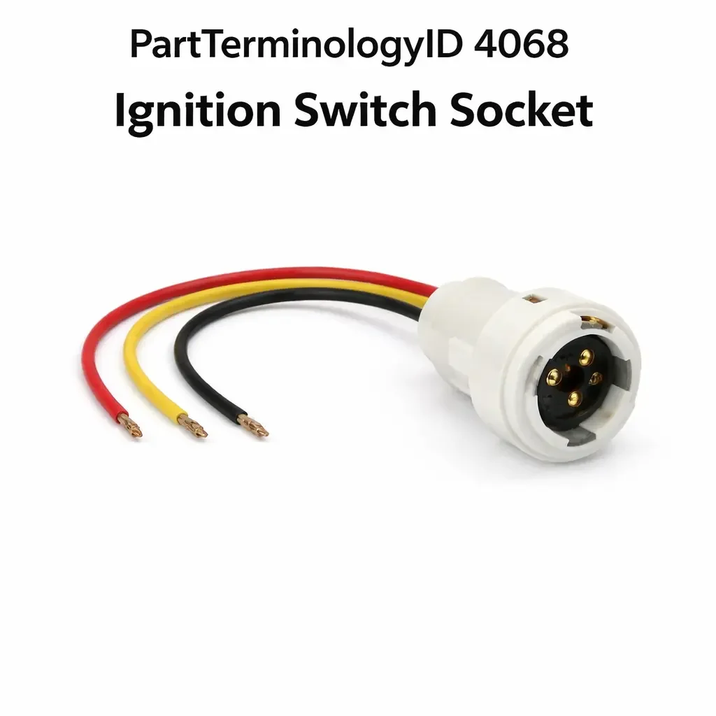
PartTerminologyID 4068, Ignition Switch Socket, is the wiring harness connector socket that mates to the electrical ignition switch mounted on the steering column or instrument panel, providing the electrical interface through which the ignition switch routes battery voltage to the accessory, run, and start circuits when the driver turns the ignition key or activates the push-button start system. That definition covers the ignition switch socket function correctly and leaves unresolved whether the socket serves a traditional key-actuated ignition switch mounted behind the lock cylinder on the steering column, a remote ignition switch mounted on the instrument panel separate from the steering column lock cylinder, or an ignition relay switching assembly where the socket delivers activation signals rather than high-current switched outputs, the terminal count and pin configuration of the connector body which varies substantially across vehicle platforms from four-terminal basic configurations through twelve or more terminal configurations on vehicles with complex ignition switching requirements, whether the socket terminals carry the full ignition-switched current loads for the accessory and run circuits or carry only low-current BCM signal inputs on vehicles where the BCM manages ignition circuit switching through relay outputs, the wire gauge and terminal material compatible with the current loads at each terminal position, and whether a failed or degraded socket terminal produces a no-start condition, an accessory circuit dropout, or an intermittent run circuit fault depending on which specific terminal position has degraded.
For sellers, PartTerminologyID 4068 is the ignition switch socket where terminal-specific symptom mapping is the most return-generating attribute, because the ignition switch socket contains multiple terminals serving different circuit functions and a fault at one terminal position produces a symptom specific to that circuit rather than a complete ignition failure. A buyer whose vehicle starts and runs correctly but whose accessory circuit drops out when the key is released from the start position has a fault at the accessory terminal rather than the run terminal. A buyer whose vehicle does not crank but whose accessory and run circuits are functional has a fault at the start terminal or in the start signal path. A buyer who replaces the complete socket assembly for an accessory-only dropout may find the correct symptom resolved but may also return the socket if the terminal fault pattern was not identified before the correct socket was ordered.
What the Ignition Switch Socket Does
Multi-terminal ignition circuit distribution and the symptom-to-terminal map
The ignition switch socket on most vehicles contains between four and eight terminals serving the following circuit categories: battery positive input that delivers unswitched power to the ignition switch at all times, accessory output that is active in the accessory key position only, run output that is active in both the run and start key positions, start output that delivers a momentary signal or voltage to the starter relay or BCM start input only during the start key position, and on some platforms a separate ignition output that is active only in the run position and not in the start position, used for components that should not be powered during cranking.
Each terminal failure produces a predictable symptom. A failed battery input terminal produces complete ignition failure across all positions. A failed accessory terminal produces loss of accessory-position-only components such as the radio and power windows when the key is in accessory but not in run. A failed run terminal produces no run circuit components including fuel pump, ignition system, and instrument cluster even though the start position may still function momentarily. A failed start terminal produces a no-crank condition while run circuit components remain active. This symptom-to-terminal mapping is the diagnostic tool that separates a socket terminal fault from an ignition switch fault before either component is ordered.
Ignition switch fault versus socket terminal fault
The ignition switch itself is the electromechanical or electronic component that the socket mates to. A failed ignition switch internal contact produces the same circuit-specific symptom as a failed socket terminal for the same circuit. Distinguishing a switch fault from a socket fault requires probing both sides of the connection: the switch output terminal and the socket terminal. Voltage present at the switch output terminal but absent at the corresponding socket terminal confirms a socket contact fault. Voltage absent at both the switch output and the socket terminal with the switch in the commanded position confirms an ignition switch internal contact fault.
Without this validation step buyers who have a switch fault replace the socket and find no change, and buyers who have a socket fault may replace the switch and find no change. The listing must direct buyers to probe both sides of the connection before ordering either component.
BCM-managed ignition switching and the signal-level socket
On current-generation vehicles the physical ignition switch or push-button start system sends low-current signal inputs to the BCM rather than directly switching the full ignition circuit current. The BCM receives the key position or start button input signal and commands the appropriate relay outputs to activate the accessory, run, and start circuits. The ignition switch socket on these applications carries low-current BCM signal inputs rather than the high-current switched outputs that traditional ignition switch sockets carry.
A fault in a BCM-managed ignition switch socket terminal produces a BCM input signal fault rather than a direct circuit dropout. The BCM may generate a fault code for the affected input and may respond with a limp-home mode or a no-start condition depending on which input is affected. A buyer who replaces the socket on a BCM-managed application and finds no change may have a BCM input circuit fault that the socket replacement did not address, or may have a BCM fault that interprets a valid socket signal incorrectly.
Why This Part Generates Returns
Buyers return ignition switch sockets because the ignition switch itself has failed and the socket terminal is delivering the switch's failed output correctly, the socket terminal fault affects only one circuit function and the buyer ordered a complete socket replacement when a terminal repair or partial splice would have resolved the specific fault, the socket is integrated into a steering column wiring harness section that requires column disassembly rather than a simple socket replacement, a BCM fault is misinterpreting a valid ignition signal and the socket is functioning correctly, and the socket terminal at fault was identified incorrectly and the replacement socket was ordered for the wrong terminal position.
Status in New Databases
PartTerminologyID 4068 is cataloged in PIES/PCdb as Ignition Switch Socket. Under PIES 8.0 and PCdb 2.0 there is no change to the terminology or classification for this PartTerminologyID.
Top Return Scenarios
Scenario 1: "Failed ignition switch internal contact, socket replaced, no change in circuit symptom"
The buyer's radio and accessory circuits do not activate in the accessory key position. The ignition switch accessory contact has failed internally. The socket accessory terminal is intact and would deliver voltage correctly if the switch were providing it. The buyer replaces the socket. The switch fault remains. The accessory circuit is still inactive because the switch is not delivering voltage to the socket terminal.
Prevention language: "Switch versus socket validation: Before replacing the socket, probe the ignition switch output terminal for the affected circuit with the key in the commanded position. Voltage at the switch output terminal but absent at the socket terminal confirms a socket contact fault. Voltage absent at both the switch output and socket terminal confirms an ignition switch internal contact fault. Replacing the socket on a switch fault will not restore the affected circuit."
Scenario 2: "No-crank condition, run circuits functional, start terminal fault identified, complete socket ordered when terminal repair sufficient"
The vehicle does not crank when the key is turned to start. The accessory and run circuits are both functional. The start terminal in the ignition switch socket has a corroded contact. The buyer orders a complete socket assembly replacement. The start terminal fault is resolved by the new socket but the buyer could have addressed the fault with a terminal repair kit at lower cost.
Prevention language: "Terminal-specific fault: Identify which circuit is affected by the symptom before ordering the complete socket. A no-crank condition with functional accessory and run circuits isolates the fault to the start terminal. A start terminal repair may be possible at lower cost than complete socket replacement if only the start terminal contact is corroded or damaged. Inspect the specific terminal before ordering the complete assembly."
Scenario 3: "BCM-managed ignition application, signal-level socket fault, BCM generates fault code, socket replaced with no change"
The buyer's vehicle generates a BCM fault code for an ignition switch input circuit. The socket on this vehicle carries low-current BCM signal inputs. The socket terminal for the affected BCM input has a high-resistance contact. The BCM receives a degraded signal and generates the fault code. The buyer replaces the socket. The high-resistance contact at the terminal is partially improved by the new socket but the BCM fault code returns because the BCM is calibrated to a lower resistance threshold than the new socket terminal achieves. The underlying harness resistance at the terminal connection is the residual fault source.
Prevention language: "BCM signal circuit validation: On BCM-managed ignition applications the socket carries low-current signal inputs rather than high-current switched outputs. A BCM fault code for an ignition switch input circuit may reflect a high-resistance socket terminal, a fault in the harness wiring between the socket and the BCM input, or a BCM input circuit fault. Confirm resistance through the socket terminal and the harness wiring before concluding the socket is the fault source."
Listing Requirements
PartTerminologyID: 4068
Switch architecture: key-actuated column-mounted, panel-mounted, or BCM-managed signal input (mandatory)
Terminal count and circuit function per terminal position (mandatory)
Terminal material and wire gauge per position (mandatory)
Current rating per terminal position (mandatory)
Switch versus socket validation note (mandatory)
Terminal-specific symptom mapping note (mandatory)
BCM-managed signal level note where applicable (mandatory)
OEM part number cross-reference (mandatory)
Catalog Checklist for ACES/PIES Teams
PartTerminologyID = 4068
Require switch architecture: key-actuated or BCM-managed (mandatory)
Require terminal count and function per position (mandatory)
Require current rating per terminal (mandatory)
Prevent switch fault socket return: switch output terminal must be probed before socket is diagnosed; voltage present at switch output but absent at socket terminal confirms socket fault; voltage absent at both confirms switch fault
Prevent BCM signal fault socket return: BCM-managed applications carry signal-level inputs; BCM fault codes for ignition switch inputs may reflect harness resistance rather than socket contact fault; resistance validation must precede socket replacement
FAQ (Buyer Language)
My radio does not work in the accessory position but everything works with the key in run. Is it the socket?
This symptom pattern isolates the fault to the accessory terminal specifically, as the run circuit is confirmed functional. Before ordering a socket, probe the ignition switch accessory output terminal with the key in the accessory position. Voltage at the switch output but no voltage at the socket terminal confirms the socket accessory contact is the fault. No voltage at the switch output confirms the ignition switch accessory internal contact has failed.
My vehicle will not crank but the dash lights and radio work. What terminal is the fault?
Functional accessory and run circuits with a no-crank condition isolates the fault to the start terminal or the starter relay circuit. Probe the start terminal at the ignition switch socket with the key in the start position and confirm voltage is present at both the switch output and the socket terminal. No voltage at the socket terminal with voltage at the switch output confirms a socket start terminal fault.
How do I identify which terminal in the socket is which circuit?
Consult the vehicle wiring diagram for the ignition switch connector terminal identification. Most diagrams label each terminal position by circuit function and wire color. The terminal positions on the socket body are typically numbered or lettered. Matching the diagram terminal label to the physical socket position before probing prevents incorrect terminal identification.
Can a bad ignition switch socket cause a no-start condition?
Yes. A failed start terminal contact in the ignition switch socket prevents the start signal from reaching the starter relay or BCM start input, producing a no-crank no-start with functional accessory and run circuits. Confirming the symptom pattern and validating the start terminal contact resolves the diagnosis before any component is ordered.
What Sellers Get Wrong About PartTerminologyID 4068
The most common error is omitting the switch versus socket validation note. The ignition switch and its socket produce identical circuit-specific symptoms when either fails and buyers cannot distinguish the two without probing both sides of the connection. Without the validation note buyers replace the socket when the switch is the failed component and return the socket when no change occurs.
The second error is omitting the terminal-specific symptom mapping. The ignition switch socket contains multiple terminals with different circuit functions and a fault at one terminal produces a predictable circuit-specific symptom. Without the mapping note buyers replace the complete socket for a single-terminal fault that could have been addressed with a terminal repair, and buyers with switch faults replace the socket on the incorrect diagnosis that the faulty circuit symptom pointed to the socket.
The third error is omitting the BCM-managed signal level note on current-generation applications. A buyer who expects the ignition switch socket on a BCM-managed vehicle to carry full ignition circuit current and probes for battery-level switched voltages will not find them, and may conclude the socket is not receiving supply when the circuit is correctly carrying low-level BCM signals.
Cross-Sell Logic
Ignition Switch: for buyers where the socket terminal validation confirms voltage is absent at the switch output terminal for the affected circuit with the key in the commanded position, indicating the ignition switch internal contact has failed rather than the socket.
Starter Relay: for buyers where the ignition switch socket start terminal is confirmed delivering voltage on key-to-start but the vehicle still does not crank, indicating the starter relay rather than the socket is the fault source.
BCM: for buyers on BCM-managed applications where the socket is confirmed delivering correct signal inputs but a BCM fault code persists, indicating the BCM input circuit or BCM logic is the residual fault source.
Steering Column Wiring Harness: for buyers where the socket is integrated into the steering column wiring section and replacement requires column disassembly, indicating the harness section rather than a discrete socket is the correct service component.
Final Take for PartTerminologyID 4068
Ignition Switch Socket (PartTerminologyID 4068) is the ignition circuit interface component where switch versus socket validation, terminal-specific symptom mapping, and BCM-managed signal level identification are the three attributes that prevent the three most common return scenarios. Every listing without switch validation sends buyers through a socket replacement when the switch is the failed component. Every listing without terminal-specific mapping sends buyers replacing complete socket assemblies for single-terminal faults. Every listing without BCM signal level identification sends buyers probing for switched voltages that do not exist on signal-level ignition switch circuits.
Together these three attributes make every listing under this PartTerminologyID complete.