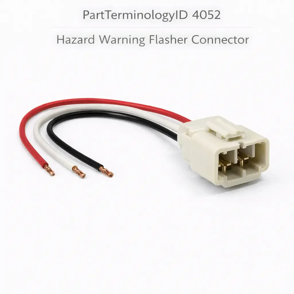
Hazard Warning Flasher Connector (PartTerminologyID 4052): Where Flasher Unit Validation and Turn Signal Circuit Isolation Prevent Connector Replacement
Written by Arthur Simitian | PartsAdvisory
PartTerminologyID 4052, Hazard Warning Flasher Connector, is the wiring harness connector that terminates the hazard warning circuit at the hazard flasher relay or module and delivers switched battery voltage simultaneously to all four turn signal lamp circuits when the driver activates the hazard warning switch, required by FMVSS 108 to operate as a four-way simultaneous flash system visible to the front, rear, and sides of the vehicle from the regulated angular arcs at a flash rate between 60 and 120 cycles per minute. That definition covers the hazard lamp activation function and the federal requirement correctly and leaves unresolved every question that determines whether the replacement connector restores continuity on all four lamp circuits simultaneously, whether the pin count matches the original flasher module connector body, whether the terminal gender is correct for the mating connector on the flasher relay or BCM output, whether the connector housing material is rated for the underhood or passenger compartment thermal environment at the installation position, whether the connector lock tab geometry seals the connector body against vibration-induced partial disconnection, whether the wire gauge in the pigtail matches the original circuit's current demand for four simultaneous lamp loads, whether the connector position coding prevents incorrect mating with an adjacent connector in the same harness cluster, whether the terminal crimp specification covers the wire gauge range in the vehicle harness, and whether the replacement connector is compatible with a solid-state LED flasher module that uses voltage-sensing flash rate control rather than thermal bimetallic current-sensing.
It does not specify the pin count, terminal gender, connector housing material rating, lock tab geometry, pigtail wire gauge, position coding, crimp specification, or LED flasher module compatibility. A listing under PartTerminologyID 4052 that states only year, make, and model without pin count and terminal gender cannot be evaluated by a technician replacing a corrosion-failed flasher connector on a vehicle where the hazard flasher module uses a six-pin connector and the adjacent turn signal flasher module uses a four-pin connector with the same housing body color and identical connector lock tab geometry, requiring the technician to confirm pin count before installation to avoid mating the wrong connector to the wrong module.
For sellers, PartTerminologyID 4052 is the electrical connector PartTerminologyID with the most direct FMVSS 108 consequence in the hazard warning system, because a failed or incorrectly installed hazard warning flasher connector disables the four-way simultaneous flash function entirely, leaving the vehicle without a federally required emergency warning signal. The hazard warning system is the primary visual emergency signal for a disabled vehicle on the roadway, for a vehicle executing an emergency lane change or stop, and for any driver requiring other road users to be alerted to an abnormal condition. A connector that produces intermittent contact on even one of the four lamp circuits results in an asymmetric flash pattern that fails FMVSS 108 and is visible to other drivers as an abnormal rear lighting condition. The urgency for a correctly specified replacement is correspondingly high.
What the Hazard Warning Flasher Connector Does
FMVSS 108 Hazard Warning System Requirements and the Four-Circuit Simultaneous-Flash Mandate
FMVSS 108 requires passenger vehicles to be equipped with a hazard warning signal system that activates all four turn signal lamps simultaneously (left front, right front, left rear, right rear) at a flash rate between 60 and 120 cycles per minute when the hazard warning switch is engaged. The four-way simultaneous flash is the defining characteristic that distinguishes the hazard warning signal from the directional turn signal, which activates only the two lamps on one side. The hazard warning flasher connector is the electrical termination point that delivers the switched hazard circuit voltage from the flasher relay or module to the four lamp circuits. Loss of continuity at this connector disables the four-way simultaneous flash, which is an FMVSS 108 violation and removes the vehicle's primary emergency warning capability.
The connector's position in the circuit makes it the single most consequential termination point in the hazard warning system outside the hazard switch and flasher module themselves. The flasher module controls flash rate and monitors circuit loads. The hazard switch routes battery voltage through the module on switch closure. The connector delivers the module's output to all four lamp circuits simultaneously. A connector with a compromised terminal at any one of its output pins drops that lamp circuit while the remaining three continue to flash, producing the asymmetric flash pattern that fails FMVSS 108 and alerts following drivers to an abnormal lighting condition that may be interpreted as a malfunction rather than an intentional warning signal.
Pin Count, Terminal Gender, and the Connector Position Coding Requirement
The hazard warning flasher connector pin count is determined by the number of circuits the flasher module outputs: one pin per lamp circuit (four minimum for the four turn signal lamps), plus pins for battery positive supply, ground, and in modern applications the CAN bus or LIN bus communication line that allows the BCM to monitor hazard system status and integrate the hazard function with the vehicle's crash response system. A replacement connector with fewer pins than the original leaves active circuits unconnected. A replacement with more pins than the original may physically fit the housing but leaves the additional pins unconnected, which is acceptable only if those additional pins are absent in the vehicle harness. The pin count must match exactly or be verified against the specific circuit content of the vehicle harness.
Terminal gender (male blade or female receptacle) determines which half of the connector mating pair the replacement covers. The flasher module typically uses a fixed male blade connector molded into the module housing, and the harness side uses a female receptacle connector that slides over the module blades and locks. Replacing the harness-side connector requires a female receptacle replacement. Replacing a connector at a junction block or relay center where both halves are discrete harness connectors requires matching the gender of the specific connector half being replaced. A listing that does not specify terminal gender forces the buyer to open the packaging to verify, which produces returns for any gender mismatch.
Connector position coding is the physical keying feature (a notch, rib, or asymmetric tab geometry on the connector housing) that prevents a connector from being mated with any connector other than its correct mating partner. Modern vehicles use position coding extensively in the underhood fuse and relay center where multiple identically sized connector housings with different pin counts and circuit functions are mounted in close proximity. The hazard flasher connector and the turn signal flasher connector may use the same housing body dimensions with different position coding features. A replacement that omits the position coding feature can be incorrectly mated with the adjacent turn signal flasher connector, connecting the hazard circuit to the wrong module and disabling both the hazard and turn signal systems simultaneously.
Connector Housing Material and Thermal Environment Rating
The hazard warning flasher connector installation position determines the thermal environment the housing material must survive. Flasher modules and relay centers mounted in the underhood fuse box expose the connector to underhood temperatures that can reach 125 degrees Celsius at the engine compartment's hottest zones during sustained high-load operation. A connector housing rated for a maximum continuous temperature of 85 degrees Celsius will exceed its glass transition temperature in an underhood relay center position, causing the housing to deform and lose the precise geometry required for secure terminal retention and connector lock engagement.
Flasher modules mounted behind the instrument panel or in the passenger compartment fuse block operate in a lower-temperature environment, typically 70 to 85 degrees Celsius maximum at the connector position. A housing rated for 85 degrees Celsius is adequate for passenger compartment installation but not for underhood installation. The listing must specify both the connector installation position and the housing material temperature rating so the buyer can confirm the replacement is rated for the specific thermal environment before ordering.
LED Flasher Module Compatibility and Voltage-Sensing Flash Rate Control
The original thermal bimetallic flasher relay controls flash rate by measuring current draw through the bimetallic strip: the strip heats and deflects under current load, opening the circuit and extinguishing the lamps, then cools and returns, closing the circuit and illuminating the lamps again. The cycle rate is a direct function of current draw. Higher current from more lamp load produces faster flash rate; lower current produces slower flash rate. LED turn signal lamps draw 10 to 20 percent of the current of equivalent incandescent lamps, which produces a flash rate three to five times faster than the standard 60 to 120 cycles per minute, a condition universally known as hyperflash.
Solid-state LED-compatible flasher modules replace the thermal bimetallic control mechanism with voltage-sensing flash rate control that maintains a constant 60 to 120 cycles per minute regardless of circuit current draw, eliminating hyperflash with LED lamps. These modules use a different internal circuit architecture and may require a different connector pin count and pin assignment than the original thermal flasher they replace. A replacement hazard warning flasher connector specified for the original thermal flasher may not be compatible with the LED-compatible solid-state module installed by a previous owner or a prior shop visit. The listing must note LED flasher module compatibility separately from standard thermal flasher compatibility and must provide the specific module type the connector is designed for.
Corrosion, Terminal Spread, and Why Connector Failure Disables All Four Hazard Lamps Simultaneously
How Terminal Corrosion at a Single Pin Fails the Entire Four-Way Flash Function
The hazard warning flasher connector failure mode is more consequential than most electrical connector failure modes because the connector's function is simultaneous four-lamp activation. A turn signal connector failure on one corner affects only one lamp circuit. A brake light connector failure affects the brake light at one corner. A hazard flasher connector failure that drops even one terminal affects the four-way simultaneous activation that defines the FMVSS 108 hazard warning function. The connector's central position in the hazard circuit means a single corroded terminal creates a system-level FMVSS 108 violation, not a single-lamp violation.
Terminal corrosion in the hazard flasher connector follows the same electrochemical mechanism as any automotive electrical connector: moisture ingress into the connector housing deposits contaminants on the terminal surfaces, and the galvanic potential between dissimilar metals in the terminal contact zone drives oxide formation at the contact interface. The hazard warning circuit's duty cycle worsens this exposure because the hazard system is used infrequently (often for weeks or months without activation), leaving the connector terminals in static contact without the self-cleaning wiping action that occurs during normal repeated connector insertion and removal cycles. Static terminals develop higher contact resistance over time as the oxide layer grows undisturbed, which manifests as a slow flash rate before complete failure as the voltage drop across the corroded contact reduces the lamp circuit voltage.
Terminal Spread, Fretting Corrosion, and Intermittent Four-Way Flash Failure
Terminal spread is the condition in which the female receptacle terminal's contact spring arms deform outward over repeated thermal expansion and contraction cycles, reducing the contact force on the mating male blade. Reduced contact force increases contact resistance and makes the terminal susceptible to fretting corrosion: the micro-vibration inherent in vehicle operation produces tiny relative motion between the mating terminal surfaces that disrupts the oxide layer continuously, but rather than cleaning the surface the fretting motion produces fine metallic debris that accumulates at the contact zone and increases resistance further.
The hazard flasher connector is particularly susceptible to terminal spread because the connector is typically in a fixed position in the fuse and relay center and is not disconnected and reconnected regularly in the course of normal maintenance. A connector that is never unmated does not receive the mechanical refreshing of the terminal contact surfaces that occurs during disconnection and reconnection. Terminal spread develops silently until the contact force drops below the threshold for stable electrical contact, at which point the hazard flash becomes intermittent: the lamps flash normally for several cycles, then one circuit drops out for a cycle or two, then recovers, producing the irregular flash pattern that buyers describe as the hazard lights flickering or missing beats.
The Case for Sealed Connector Housing Replacement Over Terminal Cleaning
A corroded hazard flasher connector terminal can be cleaned with electrical contact cleaner and a terminal pick to restore temporary contact, but the underlying cause of the corrosion (moisture ingress into the connector housing) is not addressed by cleaning the terminal surface. A connector housing that has admitted moisture once will admit moisture again because the housing's sealing geometry has been compromised, either at the connector-to-connector mating interface where the connector seal has hardened and lost its sealing compression, or at the wire entry points where the individual wire seals have cracked from thermal cycling. A sealed connector housing replacement that includes new terminal seals at every wire entry position and a new connector-face seal at the mating interface restores the housing's moisture exclusion function and eliminates the recurrence mechanism, not just the current corrosion symptom.
The cost difference between a terminal cleaning service call and a sealed connector housing replacement is small relative to the labor cost of a second return visit to address recurrent corrosion at the same connector six to eighteen months after the initial cleaning. The listing for a sealed replacement connector should make this lifecycle cost argument explicitly, noting that the sealed housing with new wire-entry seals addresses the moisture ingress mechanism rather than merely treating the corrosion symptom.
Wire Gauge, Crimp Specification, and Current Capacity for Four Simultaneous Lamp Loads
Why the Hazard Flasher Pigtail Wire Gauge Must Cover Four Simultaneous Lamp Circuits
The hazard flasher connector pigtail (the short length of wire pre-terminated to the connector for splicing into the vehicle harness) must be sized for the current demand of four simultaneous lamp circuits. A standard front or rear turn signal lamp draws approximately 2.1 amperes per lamp for a 27-watt 1156 bulb. Four simultaneous lamps draw 8.4 amperes through the hazard flasher circuit at the connector's supply pin. A pigtail using 18 AWG wire rated for 7.5 amperes continuous at the connector's supply pin is undersized for this load and will produce a measurable voltage drop at full load that slows the flash rate and reduces lamp brightness below FMVSS 108 minimums during sustained hazard warning operation.
The correct wire gauge for the hazard flasher supply circuit is 14 AWG minimum for a four-incandescent-lamp load at the maximum rated 8.4 ampere demand. LED turn signal lamp replacements reduce the total current demand to approximately 1.5 to 2.0 amperes for four lamps, which is within the capacity of 18 AWG wire, but the connector replacement is typically purchased to match the vehicle's current lamp load, which may be incandescent. The listing must state the pigtail wire gauge and the maximum current rating at the supply pin to allow buyers to verify compatibility with their lamp load before ordering.
Crimp Specification and the Wire Gauge Range for Field-Installed Terminals
Replacement hazard flasher connectors are available in two configurations: pre-terminated pigtails with wires already crimped to the connector terminals, and bare connector housings with loose terminals for the technician to crimp to the existing harness wires in the field. The pre-terminated pigtail requires no crimping tool but requires splicing the pigtail wires into the vehicle harness, which adds a splice joint to the circuit. The bare housing with field-installed terminals avoids the splice joint by allowing the technician to terminate the original harness wires directly into the replacement connector terminals.
Field-installed terminals require a ratcheting crimp tool specified for the terminal's wire gauge range. A terminal rated for 14 to 18 AWG wire requires a different crimp die than a terminal rated for 18 to 22 AWG wire, and using the wrong die produces an incomplete crimp that develops high contact resistance and eventual open circuit at the terminal. The listing for a bare housing with field-installed terminals must state the terminal crimp specification and the required crimp tool type so the buyer can confirm they have the correct tooling before ordering the bare housing configuration.
Why This Part Generates Returns
Buyers return hazard warning flasher connectors because the pin count is four and the application requires six, leaving the CAN bus communication and battery supply circuits unconnected; the terminal gender is female receptacle and the vehicle's module uses a female receptacle requiring a male blade replacement connector; the connector housing is rated for 85 degrees Celsius and installs in an underhood relay center reaching 120 degrees Celsius, causing immediate housing deformation on first thermal cycle; the position coding notch is on the left side of the housing and the vehicle's mating connector has the notch on the right side, preventing the replacement from seating fully; the pigtail wire gauge is 18 AWG and the vehicle uses 14 AWG harness wire at the hazard supply circuit, making the splice joint the circuit's current bottleneck; the connector is specified for the original thermal bimetallic flasher and the vehicle has an LED-compatible solid-state module with a different pin assignment, connecting several circuits to incorrect pins; the replacement is a bare housing and the buyer does not have a ratcheting crimp tool for the specified terminal, requiring a return for the pre-terminated pigtail configuration; and the connector housing lacks wire-entry seals and the installation position is underhood where moisture exposure will produce terminal corrosion recurrence within six to twelve months.
Top Return Scenarios
Scenario 1: "Four-pin connector delivered for six-pin application, CAN bus and supply circuits unconnected"
The buyer's hazard flasher connector has corroded terminals at two pins, producing an intermittent four-way flash. The vehicle uses a solid-state BCM-integrated hazard module with a six-pin connector: four lamp circuit output pins, one battery positive supply pin, and one CAN bus communication pin. The listing covers the vehicle without specifying pin count. The delivered connector has four pins. After installation, the lamp circuits connect but the CAN bus pin is unconnected. The BCM loses hazard system status communication and stores a U-code network fault. The hazard switch activates the lamps but the BCM cannot confirm circuit status, disabling the crash response integration that automatically activates the hazard system on airbag deployment.
Prevention language: "Connector pin count: [X] pins covering [lamp circuit 1, lamp circuit 2, lamp circuit 3, lamp circuit 4, battery positive, ground, CAN bus/LIN bus if applicable]. Verify pin count against original connector. A four-pin replacement in a six-pin application leaves the CAN bus and battery supply circuits unconnected and generates BCM network fault codes."
Scenario 2: "Female receptacle delivered, application requires male blade pigtail"
The buyer's harness-side hazard connector has a cracked housing from a prior repair attempt. The listing covers female receptacle connectors for the harness side of the flasher module connection. The buyer's vehicle uses a discrete flasher relay in the underhood fuse center where both sides of the connection are harness connectors: the relay uses a female receptacle socket and the harness uses a male blade pigtail that inserts into the relay socket. The delivered female receptacle cannot mate with the relay socket because both are the same gender.
Prevention language: "Terminal gender: [female receptacle / male blade]. This connector is the [harness side / module side] of the hazard flasher circuit connection. Verify terminal gender against the connector being replaced. A female-to-female or male-to-male pairing cannot mate."
Scenario 3: "Housing deforms on first heat cycle in underhood relay center"
The buyer installs the replacement connector in the underhood fuse and relay center. The connector housing is rated for 85 degrees Celsius continuous. The relay center position adjacent to the battery tray reaches 110 to 125 degrees Celsius on a hot day during sustained engine operation. On the first extended drive after installation, the housing softens at the lock tab base, the lock tab deforms, and the connector partially backs out of the relay socket under vibration. The four lamp circuits develop intermittent contact and the hazard flash becomes irregular.
Prevention language: "Connector housing temperature rating: [X] degrees Celsius continuous. Installation position: [underhood relay center / passenger compartment fuse block]. Underhood relay center positions may reach 120 degrees Celsius. A housing rated below this temperature will deform in an underhood installation. Confirm installation position temperature before ordering."
Scenario 4: "Position coding prevents seating, adjacent turn signal connector installs in hazard position"
The buyer's vehicle has a fuse and relay center where the hazard flasher connector and turn signal flasher connector have identical housing dimensions but different position coding notch locations. The replacement connector omits the position coding notch. The connector seats partially in both the hazard and turn signal module positions. The buyer installs it in the turn signal module position by mistake. The turn signal circuit activates all four lamps simultaneously instead of directionally. The hazard flasher module position is left unoccupied.
Prevention language: "Position coding: [notch location, for example left side or right side]. The hazard flasher connector and turn signal flasher connector on this application use identical housing dimensions. Position coding prevents incorrect module-to-connector mating. A replacement without position coding can be seated in either module position."
Scenario 5: "18 AWG pigtail spliced into 14 AWG supply circuit, voltage drop slows flash rate below FMVSS 108 minimum"
The buyer installs the replacement connector with an 18 AWG pre-terminated pigtail spliced into the vehicle's 14 AWG hazard supply wire. With four incandescent lamps drawing 8.4 amperes, the voltage drop across the 18 AWG splice length reduces the circuit voltage at the flasher module supply pin sufficiently to slow the thermal bimetallic flash rate to approximately 45 cycles per minute, below the FMVSS 108 minimum of 60 cycles per minute. The slow flash rate is interpreted by following drivers as a turn signal rather than a hazard warning pattern.
Prevention language: "Pigtail wire gauge: [AWG] rated for [X] amperes continuous. Maximum load: four incandescent turn signal lamps at 8.4 amperes. An 18 AWG pigtail is inadequate for a four-incandescent-lamp hazard load. For incandescent lamp applications, verify pigtail wire gauge is 14 AWG minimum at the supply circuit pin."
Scenario 6: "Connector specified for thermal flasher installed on LED-compatible solid-state module, pin assignment mismatch"
The previous owner replaced the original thermal bimetallic flasher with an LED-compatible solid-state module to eliminate hyperflash from LED turn signal lamps. The solid-state module uses a six-pin connector with a different pin assignment than the original thermal flasher's four-pin connector. The buyer replaces the cracked connector housing using a listing that covers the vehicle by year, make, and model without noting flasher module type. The delivered connector is specified for the original thermal flasher. The four-pin connector physically seats in the six-pin module housing but connects only the first four pins, leaving the LED driver control circuit and flash rate feedback circuit unconnected. The hazard system operates but at an incorrect flash rate.
Prevention language: "Flasher module compatibility: [thermal bimetallic OEM flasher / LED-compatible solid-state module, specify part number]. LED-compatible solid-state flasher modules may use a different pin count and pin assignment than the original thermal flasher. Verify the flasher module type installed in the vehicle before ordering."
Scenario 7: "Bare housing ordered without ratcheting crimp tool, incomplete crimp produces open circuit at terminal"
The buyer orders the bare housing configuration to avoid a splice joint in the circuit. The terminal crimp specification requires a ratcheting crimp tool with a specific die for 14 to 18 AWG wire. The buyer uses a generic slip-joint crimping plier. The incomplete crimp deforms the terminal barrel without producing the required gas-tight connection between the wire conductor strands and the terminal. The terminal develops high contact resistance within the first fifty heat cycles and produces an intermittent open on the supply pin. The buyer returns the connector as defective. The connector is not defective. The crimp is inadequate.
Prevention language: "Configuration: bare housing with field-installed terminals. Crimp specification: [terminal series, AWG range]. Required tool: ratcheting crimp tool with [die type]. A generic slip-joint plier will not produce a compliant crimp. An incomplete crimp develops high contact resistance and open circuit at the terminal within normal thermal cycling."
Scenario 8: "No wire-entry seals, underhood installation, corrosion recurrence within eight months"
The buyer replaces the corroded original connector with a replacement that uses the correct pin count, terminal gender, and housing temperature rating, but omits individual wire-entry seals at each conductor entry point. The installation position is underhood adjacent to the air intake. Condensation cycles during temperature swings over the following months draw moisture into the connector housing through the unsealed wire entry points. The replacement terminals develop the same corrosion pattern as the original within eight months of installation and the buyer returns for a second replacement.
Prevention language: "Wire-entry seals: [present at all conductor positions / absent]. For underhood installations, individual wire-entry seals at each conductor position are required to prevent moisture ingress through the conductor entry paths. A replacement without wire-entry seals in an underhood installation position will develop corrosion recurrence within the same service interval as the original failed connector."
Core Listing Attributes for PartTerminologyID 4052
PartTerminologyID: 4052
Component: Hazard Warning Flasher Connector
Pin count with circuit function mapping for each pin (mandatory)
Terminal gender: female receptacle or male blade (mandatory, in title)
Connector housing material temperature rating in degrees Celsius (mandatory)
Installation position: underhood relay center or passenger compartment fuse block (mandatory)
Position coding description: notch location or no position coding (mandatory)
Lock tab type: primary lock, secondary lock or connector position assurance, or no secondary lock (mandatory)
Connector face seal: present or absent (mandatory for underhood positions)
Wire-entry seals: present or absent per wire position (mandatory for underhood positions)
Pigtail configuration: pre-terminated pigtail or bare housing with field terminals (mandatory)
Pigtail wire gauge and current rating at supply pin (mandatory for pre-terminated pigtail)
Crimp specification and required tool type for field-installed terminals (mandatory for bare housing)
Flasher module compatibility: thermal bimetallic or LED-compatible solid-state (mandatory)
LED hyperflash note for thermal flasher listings on vehicles with LED turn signal lamps (mandatory)
CAN bus or LIN bus integration: pin present or absent (mandatory for BCM-integrated modules)
Crash response integration: hazard auto-activation on airbag deployment supported or not (mandatory where applicable)
Maximum current rating: four simultaneous lamp circuits at full incandescent load (mandatory)
Year/make/model/submodel/trim
Note for trim levels with different flasher module types (thermal vs. solid-state)
Note for vehicles with LED turn signal lamps requiring LED-compatible flasher module
Note for underhood vs. passenger compartment flasher positions within the same model year range
Catalog Checklist for ACES/PIES Teams
PartTerminologyID = 4052
Require pin count with function mapping in listing (mandatory)
Require terminal gender in title (mandatory)
Require connector housing temperature rating and installation position (mandatory)
Require position coding description (mandatory)
Require seal configuration: connector face seal and wire-entry seals (mandatory for underhood)
Require pigtail wire gauge and current rating or crimp specification (mandatory by configuration)
Require flasher module compatibility: thermal or LED-compatible solid-state (mandatory)
Prevent pin count omission: a four-pin replacement in a six-pin application leaves CAN bus and supply circuits unconnected and generates BCM fault codes; pin count must be in every listing without exception
Prevent terminal gender omission: a female-to-female or male-to-male pairing cannot mate; terminal gender must be stated in the title for every listing
Prevent temperature rating omission: a housing rated below underhood maximum will deform on first thermal cycle in a relay center installation; temperature rating and installation position must be verified before purchase
Prevent position coding omission: adjacent flasher connectors in the same relay center use identical housing dimensions with different position coding; a replacement without position coding can be seated in the wrong module position
Prevent wire gauge undersizing: an 18 AWG pigtail in a four-incandescent-lamp hazard circuit drops below FMVSS 108 minimum flash rate; supply circuit wire gauge must be stated and verified against lamp load before ordering
Prevent thermal flasher connector installation on LED-compatible module: pin count and assignment differ; flasher module type must be verified before ordering
Prevent bare housing orders without crimp tool confirmation: an incomplete crimp produces open circuit at the terminal within normal thermal cycling; crimp tool specification must be stated for all bare housing listings
Prevent unsealed connector installation in underhood positions: a replacement without wire-entry seals in an underhood installation will develop corrosion recurrence within the same service interval as the original failed connector; seal configuration must be stated for all listings covering underhood positions
Differentiate from Turn Signal Flasher Connector (PartTerminologyID 2876): the turn signal flasher connector terminates the directional turn signal circuit for two lamps on one side; the hazard warning flasher connector terminates the four-lamp simultaneous flash circuit; both may share a relay center position with identical housing geometry differentiated only by position coding
Differentiate from Hazard Warning Switch Connector (if cataloged separately): the switch connector terminates the driver-operated switch that routes battery voltage to the flasher module; the flasher connector terminates the module output to the four lamp circuits; both are in the hazard warning circuit but at different positions with different pin counts and terminal assignments
FAQ (Buyer Language)
What does the hazard warning flasher connector do?
It is the electrical connector that terminates the hazard warning flasher relay or module and delivers switched voltage to all four turn signal lamps simultaneously when the hazard switch is engaged. Without a functioning connector at this position, the hazard warning system cannot activate the four-way simultaneous flash required by FMVSS 108.
Why does my hazard flasher work sometimes and not others?
Intermittent four-way flash is the classic symptom of terminal corrosion or terminal spread at the hazard flasher connector. Corroded terminals produce high contact resistance that increases voltage drop across the circuit and slows flash rate below FMVSS 108 minimums. Terminal spread produces intermittent contact that drops individual lamp circuits for one or two flash cycles before recovering. Both conditions worsen over time without correction.
How do I know if I need the thermal flasher connector or the LED-compatible module connector?
If the vehicle has LED turn signal lamps and the flash rate is normal (not rapid hyperflash), a prior owner or shop has likely installed an LED-compatible solid-state flasher module. Confirm by visually inspecting the flasher module in the fuse and relay center and comparing the pin count of the existing connector to the listing pin count. If the pin counts differ, the module has been changed from the original thermal type.
Can I clean the terminals instead of replacing the connector?
Terminal cleaning restores temporary contact but does not address the moisture ingress that caused the corrosion. A housing that has admitted moisture will admit moisture again because the sealing geometry is compromised. A sealed replacement connector with new wire-entry seals and a new connector-face seal eliminates the recurrence mechanism and avoids a second repair visit for the same condition six to eighteen months later.
Does the hazard flasher connector also affect the turn signals?
The hazard warning flasher connector specifically terminates the hazard circuit. On vehicles with separate flasher relays for turn signals and hazard warning, a failed hazard connector does not affect directional turn signal function. On vehicles with a single integrated BCM-controlled module managing both turn signal and hazard functions, the pin assignment determines which circuits are affected by which connector. Verify the module type before assuming a hazard connector failure is isolated from the turn signal circuit.
Do I need a crimping tool to install the bare housing version?
Yes. Field-installed terminals require a ratcheting crimp tool with the die specified for the terminal's wire gauge range. A generic slip-joint plier will not produce a compliant crimp. An incomplete crimp develops high contact resistance within the first thermal cycles and produces an intermittent open circuit at the affected terminal. If you do not have the required ratcheting crimp tool, order the pre-terminated pigtail configuration instead.
Related PartTerminologyIDs
Turn Signal Flasher Connector (PartTerminologyID 2876): the adjacent connector terminating the directional turn signal relay; uses identical housing geometry on many applications with position coding differentiation; a turn signal connector failure produces single-side flash failure rather than the four-way system failure produced by hazard flasher connector failure
Hazard Warning Switch (PartTerminologyID 4053 or similar): the driver-operated switch that routes battery voltage to the flasher module on closure; a failed switch produces no hazard activation even with a functioning connector; confirm switch function before replacing connector on total hazard failure
Turn Signal / Hazard Flasher (PartTerminologyID 2811): the relay or solid-state module that controls flash rate; when the flasher module fails, the connector itself may be undamaged; confirm module function with a known-good module before replacing the connector on slow or non-functional flash
Turn Signal Light (PartTerminologyID 2872): the lamp that the hazard flasher connector powers simultaneously on all four corners; a failed lamp on any corner produces an asymmetric hazard flash; confirm all four turn signal lamps function before replacing the connector on asymmetric flash complaints
Status in New Databases
PIES/PCdb: PartTerminologyID 4052, Hazard Warning Flasher Connector
PIES 8.0 / PCdb 2.0: No change in PartTerminologyID or terminology label
Final Take for PartTerminologyID 4052
Hazard Warning Flasher Connector (PartTerminologyID 4052) is the electrical connector PartTerminologyID with the most direct FMVSS 108 hazard warning system consequence in the connector series. The safety-motivated buyer replacing a corroded or cracked housing needs the pin count and terminal gender to avoid mating the wrong connector to the wrong module. The technician installing in an underhood relay center needs the housing temperature rating to avoid immediate deformation on the first heat cycle. The shop replacing a connector on a vehicle with LED turn signal lamps needs the flasher module compatibility note to avoid installing a thermal flasher connector on an LED-compatible solid-state module with a different pin assignment. The buyer ordering a pre-terminated pigtail for a four-incandescent-lamp load needs the wire gauge and current rating to avoid a voltage drop that slows the flash rate below FMVSS 108 minimums.
State the pin count with circuit function mapping in the title. State the terminal gender. State the housing temperature rating and installation position. State the position coding description. State the seal configuration for underhood installations. State the pigtail wire gauge and current rating or the crimp specification for bare housings. State the flasher module compatibility. For PartTerminologyID 4052, pin count with circuit function mapping, housing temperature rating, and flasher module compatibility are the three attributes beyond the standard fitment checklist that prevent the three most costly and least obvious return scenarios in the hazard warning flasher connector buyer population.