Twilight Sentinel Relay (PartTerminologyID 3912): Diagnosis, Return Prevention and Listing Guide
Written by Arthur Simitian | PartsAdvisory
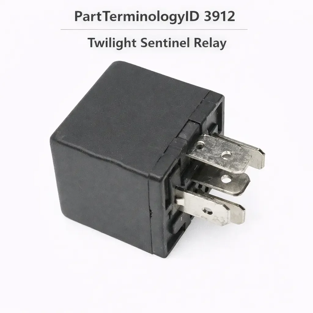
The Twilight Sentinel Relay, cataloged under PartTerminologyID 3912, is the self-contained control module that manages the Twilight Sentinel automatic headlight system on General Motors vehicles where this feature was offered, spanning from its introduction in the late 1950s through various generations of GM passenger cars and light trucks into the early 2000s. The component is more accurately a relay module or lamp control module than a single discrete relay: it contains an ambient light comparator circuit that receives the signal from a dashboard-mounted photocell, an RC-based time delay timer circuit that governs how long the headlamps remain on after the ignition is switched off, and an output relay whose contacts complete the headlamp supply circuit when the module determines that darkness conditions have been met and the system switch is active.
The Twilight Sentinel system serves two functions simultaneously. The first is automatic dusk-to-dawn headlamp activation: when the photocell detects ambient light falling below a calibrated threshold, the module energizes its output relay, which completes the headlamp circuit independently of the manual headlight switch. The second is an adjustable exit-delay function: when the ignition is switched off in low-light conditions, the module holds the headlamps on for a driver-adjustable duration from a minimum of a few seconds to a maximum of approximately three minutes, allowing the driver time to exit the vehicle and reach a building entrance before the lights extinguish. The delay duration is set by the Twilight Sentinel control knob on the instrument panel.
The Twilight Sentinel circuit operates in parallel with the manual headlight switch. When the manual headlight switch is placed in the On position, it takes direct control of the headlamps and overrides the Twilight Sentinel system. The Twilight Sentinel control is active only when the manual switch is in the Off position and the ignition is in the Run or On position. This parallel architecture means a failed Twilight Sentinel module does not prevent manual headlight operation: the driver can always operate the headlights through the manual switch regardless of module condition.
The Chrysler equivalent of this system was marketed as the Safeguard Sentinel and shares the same functional architecture. The generic PartTerminologyID applies across the GM nomenclature and equivalent applications.
Status in New Databases PartTerminologyID 3912, Twilight Sentinel Relay PIES 8.0 / PCdb 2.0: No change.
What the Relay Does
Photocell Input and the Comparator Circuit
The photocell sensor is a photodiode or photoresistor mounted in the instrument panel facing upward or forward through the windshield, positioned to receive ambient skylight rather than direct lamp illumination. As ambient light decreases toward dusk, the photocell's resistance increases. The module's comparator circuit monitors this resistance and compares it against a calibrated threshold. When the photocell resistance crosses the threshold indicating low-light conditions, the comparator circuit output changes state and activates the module's internal timing and relay circuits. When ambient light increases toward dawn, the comparator detects the photocell resistance decreasing below the threshold and deactivates the relay circuit, extinguishing the headlamps.
The sensitivity of the photocell's activation threshold on earlier applications was adjusted by a mechanical aperture disc mounted over the photodiode, with Early and Late positions that varied how much light could reach the sensor. Later applications used the position of the Twilight Sentinel control knob to set both the sensitivity threshold and the exit-delay duration in a single control. The sensitivity adjustment changes the ambient light level at which the headlamps activate and deactivate: set toward Early, the lights come on sooner as dusk approaches; set toward Late, they come on only in deeper darkness.
The photocell is a separately mounted component from the relay module. A failed photocell produces a failed Twilight Sentinel system, but the module itself may be intact. Testing the photocell requires confirming its resistance is within the specified range for daylight conditions, typically 23,000 to 31,000 ohms, and that the resistance increases substantially when covered or darkened. A photocell that is stuck at low resistance produces a module that never activates because the comparator circuit always reads a daylight condition. A photocell that is stuck at high resistance produces a module that activates in daylight and keeps the headlamps on continuously during ignition-on conditions.
The Time Delay Circuit
The exit-delay portion of the Twilight Sentinel function is governed by an RC timing circuit within the module. When the ignition is switched off in low-ambient-light conditions, the comparator circuit detects darkness and the timing circuit begins its countdown. The output relay remains energized for the duration set by the control knob, then opens and extinguishes the headlamps. At the minimum position, the delay is a few seconds. At the maximum position, the delay is approximately three minutes depending on the specific module generation.
The RC timing circuit uses capacitors whose effective capacitance determines the delay interval. Capacitor degradation from age and heat cycling is a documented failure mode in these modules and produces shortened delay times. A module that provides only a very brief delay or no delay at all before extinguishing the headlamps has most likely experienced capacitor degradation in the timing circuit, even though the relay's output contacts may be fully functional.
The Output Relay and the Dominant Failure Mode
The output relay within the module operates the headlamp circuit contacts. On applications where the module drives the headlamps directly through its relay contacts, the relay carries the full current of the headlamp circuit. On applications where the module drives a separate headlamp relay through a lower-current coil signal, the module's output relay carries only the coil current.
The dominant reported failure mode for Twilight Sentinel modules is cracked solder joints on the module's circuit board rather than relay contact failure. The module is a multi-layer assembly of discrete resistors, capacitors, and the relay soldered to a printed circuit board. Thermal cycling from engine heat and age causes solder joints to crack, producing intermittent or complete loss of module function that varies with temperature and module orientation. Many technicians and owners have successfully repaired these modules by identifying and reflowing the cracked solder joints, restoring full function without replacing the module. This repair history is significant for catalog listing purposes: a buyer who is experiencing intermittent Twilight Sentinel behavior and who receives a replacement module that initially appears to resolve the fault may experience recurrence if the new module is also subject to solder joint fatigue, which is common in aged OEM stock.
Top Return Scenarios
Headlights Stuck On in Daylight: Photocell Is the More Likely Fault
A vehicle whose headlights activate and remain on regardless of ambient daylight, with the manual switch off and the Twilight Sentinel control in the active position, has a fault in the comparator input circuit or the photocell. The most common cause is a failed photocell that is presenting high resistance to the module at all times, which the comparator reads as a permanent low-light condition. Replacing the relay module in response to this symptom without testing the photocell first results in a no-improvement return if the photocell is the fault.
The photocell test is simple: with the ignition on and the Twilight Sentinel activated, cover the photocell completely. The headlamps should activate or remain on. Uncover the photocell in bright daylight: the headlamps should extinguish after approximately 20 to 30 seconds as the comparator registers the daylight condition. If the headlamps do not extinguish when the photocell is exposed to strong daylight, the photocell is suspect. Measuring the photocell's resistance in direct sunlight and comparing it against the specified daylight range confirms or eliminates the sensor.
Headlights Never Activate Automatically: Module, Photocell, Fuse, or Switch
A Twilight Sentinel system that never activates automatically in low-light conditions, with the control knob in the active position and the manual headlight switch off, has a fault somewhere in the activation circuit. The fault candidates include a failed module, a failed photocell stuck at low resistance, a blown fuse in the Twilight Sentinel circuit supply, a failed control knob switch contact, or a wiring fault between the photocell and the module or between the module and the headlamp circuit.
The fastest isolation test is to cover the photocell completely and then switch the ignition to the On position with the Twilight Sentinel control active. If the headlamps do not activate within 20 to 30 seconds with the photocell completely obscured, the activation circuit has a fault between the photocell and the output to the headlamps. Confirming supply voltage is present at the module's ignition input terminal, and that the control knob switch is delivering its signal to the module, isolates whether the module itself is the fault or whether an upstream component has failed.
Intermittent Operation: Cracked Solder Joint Before Module Replacement
Intermittent Twilight Sentinel function that varies with temperature, with physical vibration of the module, or with ambient conditions is the strongest diagnostic indicator of cracked solder joints rather than a component failure within the module. A module that activates and deactivates correctly some of the time has functioning comparator and relay circuits. A purely failed component typically produces consistent failure, not intermittent variation. Before purchasing a replacement module, an owner or technician with soldering capability should inspect the module's circuit board for cracked solder joints under magnification. The joints at multiply-connected pins and at the relay's solder feet are the most common failure locations. Reflowing these joints restores function in a significant proportion of intermittent-failure cases.
A buyer who replaces the module without addressing solder joints may receive an aged OEM replacement module that is subject to the same solder fatigue, producing a repeat failure within a short interval. The listing should acknowledge this failure mode and the solder repair option, particularly for buyers of vehicles where replacement modules are scarce or expensive.
Exit Delay Shortened or Absent: Capacitor Degradation
A module that activates headlights correctly in low ambient light but extinguishes them very quickly after ignition-off, without providing the user-set delay interval, has a timing circuit fault rather than a relay fault. Capacitor degradation within the RC timing circuit is the most common cause. The relay and comparator may be fully functional. Replacing the module resolves this symptom if the replacement module's capacitors are in good condition, but if the replacement is aged OEM stock, the same capacitor degradation may be present.
Buyers experiencing this specific symptom of lost delay function should understand that the fault is in the timing circuit components rather than in the relay contacts, and that the entire module is the replaceable unit because the timing circuit is not serviceable separately as a catalog item.
Manual Override Misunderstood as System Fault
A consistent source of customer contacts that do not result in module replacement is drivers who discover that the Twilight Sentinel does not activate headlights when the manual headlight switch is in the On position. The manual switch takes direct control of the headlamp circuit and overrides the Twilight Sentinel entirely. This is the designed parallel architecture: the Twilight Sentinel can only exercise headlamp control when the manual switch is in the Off position. A driver who leaves the manual switch on after operating it manually and then expects the Twilight Sentinel to take over automatic control has not discovered a system fault. No module replacement is appropriate.
This misunderstanding is particularly common among drivers who recently purchased a used vehicle equipped with Twilight Sentinel and are unfamiliar with the system's operating requirements. A listing note that clarifies the parallel architecture and the requirement for the manual switch to be in the Off position prevents this buyer category from converting to a module replacement purchase.
Listing Requirements
Every listing for PartTerminologyID 3912 should include:
ACES fitment data confirmed from factory documentation for specific GM vehicle lines and model years equipped with the Twilight Sentinel option; this is a factory option rather than a standard feature on most platforms and was not present on all vehicles of a given model year; the RPO code T82 identifies the Twilight Sentinel option on applicable GM vehicles
A description of the module's integrated function: it contains the photocell comparator circuit, the RC time delay circuit, and the output relay in a single assembly; all three subsystems are replaced together as the module
A note that the photocell sensor is a separate component from the module, and that photocell failure produces headlights stuck on or stuck off and must be tested before module replacement
A note that the dominant physical failure mode is cracked solder joints, and that intermittent function varying with temperature or module orientation is the primary indicator
A note that the manual headlight switch must be in the Off position for Twilight Sentinel to exercise headlamp control; the system does not compete with or override a manually activated headlight switch
A note that a shortened or absent exit delay indicates capacitor degradation in the timing circuit; module replacement addresses this if the replacement module's capacitors are in good condition
Frequently Asked Questions
My headlights stay on all the time during the day even with the Twilight Sentinel switch in a normal setting. Is the module bad?
Headlights on continuously in daylight with the Twilight Sentinel active is most likely caused by a failed photocell presenting a permanent high-resistance low-light reading to the module's comparator. Expose the photocell to direct sunlight and confirm it presents a resistance in the 23,000 to 31,000 ohm range. If the resistance is much higher than this range, the photocell has failed and should be replaced before the module. If the photocell resistance is correct in daylight and the headlamps still remain on, the module's comparator circuit has failed in the activated state.
My Twilight Sentinel never turns the headlights on automatically. The control knob is on and the manual switch is off. What should I check first?
Cover the photocell completely with opaque material, then switch the ignition to On with the Twilight Sentinel control active. The headlamps should activate within approximately 20 to 30 seconds. If they activate with the photocell covered, the system is functioning and the photocell is allowing too much light to reach the comparator: either the photocell is degraded, the sensitivity adjustment is set very late, or ambient light is higher than the calibrated threshold during your testing conditions. If the headlamps do not activate even with the photocell covered, check the fuse for the Twilight Sentinel circuit and confirm the control knob is delivering its signal to the module before concluding the module has failed.
My Twilight Sentinel works intermittently. Sometimes the headlights activate and sometimes they do not. Is this the module?
Intermittent operation that varies with temperature, vibration, or the module's physical orientation is the primary indicator of cracked solder joints in the module's circuit board. Before purchasing a replacement module, physically move or flex the module while the system is active and observe whether this changes the behavior. If function changes with module movement, inspect the circuit board for cracked solder joints and reflow them. This repair resolves the fault in the majority of intermittent cases and avoids the cost and scarcity issues of replacement module procurement.
The headlights turn on automatically in the dark but turn off almost immediately after I shut off the ignition instead of staying on for the delay I set. What is wrong?
A shortened or absent exit delay indicates degraded capacitors in the module's RC timing circuit. The relay and comparator portions of the module are functioning. Module replacement is the catalog solution, but aged OEM replacement modules may have the same capacitor degradation. A technician experienced with electronics can restore delay function by replacing the specific capacitors in the timing circuit rather than replacing the entire module.
Will the Twilight Sentinel still work if I manually turn on the headlights?
No. The Twilight Sentinel can only control the headlamps when the manual headlight switch is in the Off position. When the manual switch is On, it takes direct control of the headlamp circuit and the Twilight Sentinel is bypassed entirely. If you have manually activated the headlights and want the Twilight Sentinel to take over, return the manual switch to Off.
My car has automatic headlights but I do not see a Twilight Sentinel relay in the parts catalog. Does it have one?
The Twilight Sentinel was an optional feature on specific GM models, identified by the RPO option code T82 on the vehicle's option sticker in the trunk or door jamb. Not all GM vehicles with automatic headlight control use the Twilight Sentinel architecture. Later GM platforms integrated automatic headlight control into the body control module without a discrete Twilight Sentinel relay module. If your vehicle's option code list does not include T82, the Twilight Sentinel module is not present and automatic headlight behavior, if any, is handled by BCM logic.
What Sellers Get Wrong
Listing without confirming the T82 option code in the ACES data
The Twilight Sentinel was not standard equipment on all vehicles of a given model year; it was an RPO option. A vehicle of the same make, model, and year may or may not have the Twilight Sentinel relay module depending on how it was originally ordered. ACES data that lists all vehicles of an eligible year without filtering for the T82 option will generate no-find returns from buyers whose vehicle lacks the module and its associated wiring. Confirming the RPO code is the correct ACES basis for this PartTerminologyID.
Conflating the relay module with the photocell
The Twilight Sentinel photocell sensor and the relay module are separate catalog items. A buyer who is experiencing headlights stuck on in daylight and who correctly identifies this as a Twilight Sentinel fault may not know whether the photocell or the module is the failed component. A listing that directs buyers to test the photocell before purchasing the module prevents photocell-fault buyers from ordering a module that will not resolve their symptom.
Not addressing solder joint repair as a documented alternative for intermittent faults
The solder joint repair procedure is widely documented in GM enthusiast communities and has a high success rate for intermittent Twilight Sentinel module failures. A listing that presents only module replacement, without acknowledging that intermittent faults are commonly resolved through solder repair, will occasionally convert buyers whose module can be repaired rather than replaced, particularly on vehicles where genuine replacement modules are scarce or expensive. Acknowledging the repair option while offering the module for cases where repair is not viable or desired serves the buyer more accurately.
Not noting that the manual switch must be off for the system to function
The parallel circuit architecture, requiring the manual headlight switch to be in the Off position for Twilight Sentinel control to function, is the single most common source of apparent system malfunction that is actually correct operation. A listing or description that does not explain this will continue to generate contacts from drivers who believe the system is failed because it does not operate while the manual switch is on.
Treating this as equivalent to BCM-integrated automatic headlight control
Modern BCM-integrated automatic headlights and the Twilight Sentinel relay module are separate architectures serving a similar function. Parts research traffic for automatic headlight faults on late-model BCM-controlled vehicles should not arrive at this PartTerminologyID. A listing with overly broad descriptive language that does not specify the Twilight Sentinel as a discrete module distinct from BCM headlight control will attract mismatched buyers whose vehicle has no module to replace.
Cross-Sell Logic
Twilight Sentinel photocell sensor (the ambient light input component that the relay module receives its activation signal from; a failed photocell is as likely as a failed module to produce headlights stuck on or stuck off; should always be tested before module replacement; separately cataloged from the module)
Twilight Sentinel control switch or knob (the driver interface component that sets sensitivity threshold and exit delay duration; a failed switch contact can prevent the module from receiving its activation signal regardless of module and photocell condition; a less common fault but appropriate to confirm before module replacement when the system has no response to photocell input)
Headlamp relay or headlamp switch (on applications where the Twilight Sentinel module drives a separate headlamp relay rather than directly switching the headlamp circuit, the headlamp relay is a distinct component in the activation path; a failed headlamp relay produces no lamp illumination even when the Twilight Sentinel module is commanding activation)
Fuse for the Twilight Sentinel circuit (mandatory pre-check before module replacement; a blown fuse removes the module's ignition supply and produces a complete system no-activation failure identical to module failure)
Final Take
PartTerminologyID 3912 serves a specific and narrow buyer population: owners of GM vehicles from roughly the 1960s through the early 2000s who are maintaining or restoring the Twilight Sentinel automatic headlamp option. The application scope is bounded by the T82 option code rather than by vehicle model and year alone, and the ACES discipline of confirming the option's presence is the listing's most important fitment safeguard.
Within that scope, three diagnostic realities shape the return risk. The photocell is as likely as the module to be the fault for the most common symptom of headlights stuck on in daylight, and ordering the module without testing the photocell first converts a defined percentage of photocell buyers. The cracked solder joint failure mode is the dominant physical fault pattern and is repairable without module replacement in a substantial proportion of intermittent cases, which means a listing that does not acknowledge it will generate module purchases by buyers who would prefer to attempt repair first. And the parallel circuit architecture means that manual switch position determines whether the Twilight Sentinel can function at all, and a meaningful percentage of apparent system faults are not faults at all.
A listing that addresses all three of these elements, in addition to the basic photocell-test procedure, the delay-circuit capacitor failure mode, and the RPO scope boundary, serves the technically informed buyer this PartTerminologyID attracts.
Disclaimer
This guide is intended for catalog research, parts listing, and diagnostic reference. Twilight Sentinel module design, circuit architecture, photocell location, and control switch configuration vary by vehicle line, model year, and option package. Always confirm application data against factory service documentation and the vehicle's original option code list before finalizing a listing or parts recommendation. PartsAdvisory and its contributors are not responsible for fitment errors arising from catalog data that has not been independently verified against official OEM sources.