Turn Signal Relay (PartTerminologyID 3904): Diagnosis, Return Prevention and Listing Guide
Written by Arthur Simitian | PartsAdvisory
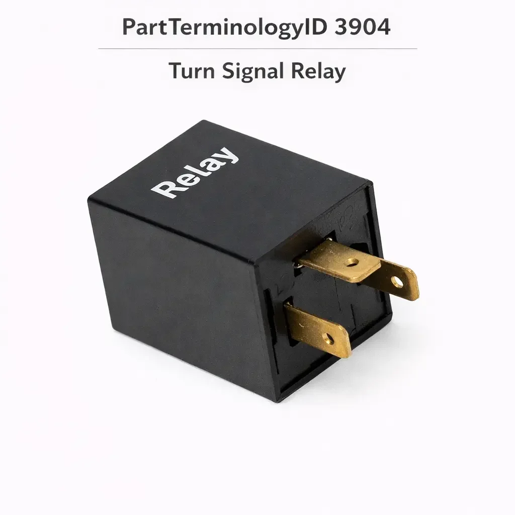
The Turn Signal Relay, cataloged under PartTerminologyID 3904, is the self-contained timing and switching module that makes the vehicle's turn signal lamps flash on and off at a regulated rate when the turn signal stalk is activated. Unlike a conventional relay that simply opens or closes contacts in response to a coil signal, the turn signal relay integrates the switching function with an internal timing mechanism: either a thermally actuated bimetallic strip that heats and cools through the lamp current itself, or an electronic timer circuit that generates the on-off cycle independently of lamp load. The result is a single-unit component that receives ignition-switched power and turn-switch input, and delivers an interrupted output to the turn signal lamps.
This PartTerminologyID spans a wide range of vehicle generations and circuit architectures that differ fundamentally in how flashing is achieved, who the correct replacement buyer is, and what the most common misdiagnosis looks like. Thermal flashers, found on older vehicles, are load-dependent devices whose flash rate is determined by how much current the lamp circuit is drawing. Electronic flashers, found on mid-generation vehicles, use solid-state timing circuits that produce a consistent rate regardless of load. BCM-integrated flash control, found on most late-model vehicles, eliminates a discrete relay entirely: the body control module drives the turn signal circuits directly through internal solid-state outputs, and no physical relay exists to replace. Each architecture requires different diagnostic logic and has different return risk profiles.
The practical scope of this PartTerminologyID is bounded by the presence of a discrete, physically replaceable flasher unit in the vehicle's fuse and relay panel or mounted independently in the dash or underhood. On BCM-integrated platforms where turn signal timing is handled entirely within the body control module software, purchasing a turn signal relay produces no improvement and no installation point.
Status in New Databases PartTerminologyID 3904, Turn Signal Relay PIES 8.0 / PCdb 2.0: No change.
What the Relay Does
Thermal Flasher Architecture: Load-Driven Timing
The thermal flasher operates on the principle that the current drawn by the turn signal lamps generates heat within the flasher unit. When the turn stalk is activated, current flows from the ignition supply through the flasher's internal heating element and bimetallic strip, then to the lamps. As the current heats the bimetallic strip, the two dissimilar metals expand at different rates, causing the strip to bend and open the circuit. With the circuit open, the lamps go off, current stops flowing, the strip cools, and it snaps back to the closed position. Current flows again and the cycle repeats. The clicking sound is produced by the mechanical snap of the strip.
The thermal flasher's most important diagnostic characteristic is that its flash rate is directly tied to the current the lamp circuit draws. The normal flash rate, typically 60 to 120 flashes per minute, is calibrated for the expected current draw of the full set of incandescent bulbs on that vehicle. If a bulb burns out and reduces circuit load, the strip heats and cools faster, and the flash rate increases. This is the bulb-out warning mechanism: fast flashing indicates a burned bulb, not a failed flasher. A thermal flasher installed in a circuit where all bulbs have been replaced with LEDs will receive far less current than it was calibrated for, and will either not flash at all or flash very rapidly, because the LED current is insufficient to heat the bimetallic strip to its operating temperature in the normal flash interval.
The thermal flasher's circuit terminals are typically the X terminal, which connects to the ignition-switched power supply, and the L terminal, which connects to the lamp circuit through the turn switch. The thermal flasher does not require a separate ground connection because the circuit ground is completed through the lamp bases. Some applications use a three-terminal version with an additional P terminal for a dashboard pilot lamp.
Electronic Flasher Architecture: Load-Independent Timing
The electronic flasher uses a solid-state timer circuit, typically built around a transistor-switched output, to generate the on-off cycle at a fixed rate that is independent of the current the lamp circuit draws. The flash rate is set by component values in the timer circuit and does not change when a bulb burns out or when LED bulbs are substituted for incandescent ones. This eliminates the thermal flasher's bulb-out warning capability but provides consistent flash rate regardless of lamp type or load variation.
Electronic flashers typically have three terminals: a power supply input, a lamp circuit output, and a ground return. Because the timing circuit requires a proper ground to operate, the ground terminal must be connected; the thermal flasher's practice of completing ground through the lamp bases does not apply. An electronic replacement installed in a socket that was originally wired for a thermal flasher may require attention to the polarity of the supply and lamp terminals, because the socket wiring may have the X and L terminals reversed from the electronic unit's requirements. A thermal flasher does not care which terminal receives supply and which connects to the lamps, because the current path through the bimetallic strip is the same in either direction. An electronic flasher is polarity-sensitive and will not operate, or will operate incorrectly, if installed with the supply and lamp wires reversed at the socket.
BCM-Integrated Architecture: No Discrete Relay
On late-model vehicles where the BCM controls turn signal function, the BCM monitors the turn switch stalk position and drives the turn signal lamp circuits directly through internal solid-state outputs. The BCM also monitors the current draw on each lamp circuit and sets a diagnostic trouble code or activates the fast-flash bulb-out indication if a circuit fault is detected. On these platforms there is no flasher unit in the fuse panel or mounted under the dash. A buyer who searches the relay panel for a turn signal relay, cannot find one, and orders a replacement based on catalog listings, is purchasing a component their vehicle does not have.
On BCM-integrated platforms, LED bulb substitution is not resolved by replacing or upgrading the flasher. The BCM's load-monitoring circuit detects the reduced current of the LED bulbs and interprets it as a bulb-out fault, triggering fast-flash regardless of bulb condition. Resolution on these platforms requires either installing load resistors in parallel with each LED bulb to simulate the expected incandescent current draw, or having the BCM's turn signal lamp-out detection threshold reprogrammed through a dealer or compatible scan tool with module programming capability. Neither of these remedies involves the turn signal relay.
Hazard vs. Turn Signal Circuit
On many vehicles, the turn signal function and the hazard warning function use separate flasher units or separate internal circuits within a combination flasher module. When diagnosing a turn signal complaint, confirming whether the hazard function is also affected is the fastest single diagnostic step to identify the circuit scope of the fault.
If the hazard lights flash correctly and only the turn signals do not, the fault is in the turn signal-specific circuit: the turn signal relay itself if a discrete turn relay is separate from the hazard relay, the turn signal switch stalk, the wiring between the stalk and the relay or BCM, or a bulb fault on only one side. If both hazards and turn signals have failed, the fault is in the shared power supply to the flasher, the combination flasher unit that serves both functions, or a fuse that protects both circuits. If only one direction's turn signal is affected and the hazard on that side still works, the fault is almost certainly in the turn signal switch stalk or its wiring rather than in the relay.
Top Return Scenarios
Burned Bulb Diagnosed as Relay Failure on Thermal Flasher Applications
The most common misdiagnosis generating returns for this PartTerminologyID on thermal flasher applications is a burned-out bulb that produces fast-flash. A driver who notices rapid blinking and interprets it as a relay malfunction rather than a bulb-out warning is the most likely incorrect buyer. The thermal flasher is functioning exactly as designed when it produces fast-flash in response to a failed bulb. Replacing the relay without first inspecting all turn signal bulbs on the affected side will result in installation of a new relay with no change in flash behavior, because the bulb fault was the cause.
The correct first diagnostic step for fast-flash on a thermal flasher vehicle is visual inspection and electrical test of all turn signal bulbs on the affected side: front, rear, and side marker where equipped. Confirming all bulbs are present and drawing current before replacing the relay eliminates this misdiagnosis category entirely.
LED Retrofit Producing Hyperflash or No Flash
A buyer who has replaced incandescent turn signal bulbs with LEDs and now experiences hyperflash or no flash at all is experiencing a compatibility fault between the LED bulbs' reduced current draw and the flasher unit's expectations. On thermal flasher applications, the solution is to replace the thermal flasher with an LED-compatible electronic flasher that operates at a fixed rate regardless of load. On electronic flasher applications with a lamp-out warning circuit that monitors current draw, the solution may be an LED-compatible flasher designed for lower minimum load thresholds. On BCM-integrated applications, as described above, the turn signal relay is not involved and replacing it produces no improvement.
A buyer on a thermal flasher application who purchases an LED-compatible electronic flasher in response to hyperflash from an LED retrofit is the correctly qualified buyer for this PartTerminologyID. A buyer on a BCM-integrated application who purchases the relay expecting to resolve LED hyperflash is an incorrect buyer who will return the relay unused.
Turn Signal Switch Stalk Failure Misdiagnosed as Relay
The turn signal switch stalk is the component that closes the circuit between the relay's lamp output and the specific side's lamp wiring when the driver moves the stalk. A stalk that has developed failed contacts, a broken mechanical cancel cam, or a corroded connector produces turn signal failure on one or both sides without any fault in the relay. On BCM-integrated platforms, the stalk's position signal is a digital input to the BCM rather than a direct switched circuit, and a stalk fault produces a BCM input fault rather than a relay fault.
The fastest diagnostic confirmation of a relay fault versus a stalk fault on a traditional circuit is to swap the turn signal relay with the hazard relay if the two are identical units in adjacent sockets, then test turn signal function. If function is restored with the known-good hazard relay in the turn signal position, the turn signal relay is confirmed faulty. If function is not restored, the fault is downstream of the relay socket: in the stalk, the wiring, or a bulb circuit fault.
Relay Replaced but Flash Rate Still Incorrect After Thermal-to-Electronic Swap
A buyer who replaces a thermal flasher with an electronic unit and finds the signals either do not flash at all or flash at the wrong rate may have installed the electronic unit in a socket where the supply and lamp terminal wires are reversed. Because thermal flashers are not polarity-sensitive, the original socket wiring may not respect the X and L terminal assignments, and any reversal in the socket passes unnoticed with the thermal unit. An electronic unit installed with reversed polarity will not operate correctly. Testing the socket with a multimeter to confirm which terminal has the ignition supply and which connects to the lamp circuit, and matching these to the replacement unit's marked terminals, resolves this fault without returning the relay.
An electronic replacement that requires a separate ground wire must also have that ground wire connected to vehicle chassis ground. A socket that was originally wired for a two-terminal thermal flasher will not have a ground wire in the socket, and the electronic unit's ground lead must be routed and connected separately during installation. Failure to connect the ground produces no flash or erratic flash from an otherwise functional electronic unit.
One Side Flashes, Other Side Does Not, Hazards Work Normally
Asymmetric turn signal failure where one side works and the other does not, combined with normal hazard operation on both sides, is consistent with a fault in the turn signal switch stalk, a wiring fault on the affected side, or a blown bulb on the affected side on a thermal flasher vehicle. It is not consistent with a relay failure, because a relay failure typically affects the entire flash circuit rather than one side only. The turn signal relay applies the same switching to both left and right circuits through the stalk: when the stalk is in neutral, neither circuit receives the flash output; when the stalk is left or right, the stalk connects the relay output to the appropriate side's lamps. A relay that has failed completely eliminates flash output entirely. A relay that has failed partially but still produces output would affect both sides.
A one-sided failure with functional hazards is the clearest indication that the stalk or the wiring from the stalk to the lamps on that side is the fault. The relay is almost never the correct replacement for a strictly one-sided failure.
No Flash at All, Fuse Is the Actual Fault
The turn signal circuit is protected by one or more fuses in the vehicle's fuse panel. A blown fuse removes the power supply to the relay entirely and produces a complete failure of turn signal function that is indistinguishable from relay failure at the driver's level. The fuse is the mandatory first check before any relay diagnosis. On many vehicles the turn signal fuse is shared with or adjacent to the hazard warning fuse, and a single blown fuse can affect both functions. Confirming fuse integrity requires no tools beyond a fuse puller and visual inspection, or a test light for a faster check of whether voltage is present at both sides of the fuse with the ignition on.
Listing Requirements
Every listing for PartTerminologyID 3904 should include:
ACES fitment data confirmed from factory documentation for applications with a discrete, physically replaceable turn signal flasher unit; must exclude BCM-integrated applications where no physical relay is present
A clear statement of whether the application uses a thermal or electronic flasher, because this determines compatibility with LED bulbs and the pin orientation requirements for replacement
A pin count and terminal layout description (2-pin thermal, 3-pin with P terminal for pilot lamp, 3-pin electronic with dedicated ground) sufficient for a buyer to confirm socket compatibility before purchasing
A note that on thermal flasher applications, fast-flash indicates a burned bulb as the first diagnostic step, not relay failure
A note that on BCM-integrated applications, LED hyperflash is resolved through load resistors or BCM reprogramming, not through relay replacement
A note that the hazard circuit and turn signal circuit may use separate relays on some applications, and that the hazard function working normally while turns fail narrows the fault to the turn-specific circuit
Frequently Asked Questions
My turn signals are blinking very fast. Does that mean the relay is bad?
On thermal flasher applications, rapid blinking most commonly indicates a burned-out turn signal bulb. The thermal flasher heats and cools faster with a reduced lamp load, producing the fast-flash rate. Inspect all turn signal bulbs on the affected side before replacing the relay. If all bulbs are present and functioning and rapid blinking continues, the thermal flasher may have failed or may be receiving incorrect current due to a wiring fault. On BCM-integrated applications, rapid blinking is a bulb-out or circuit fault indication generated by the BCM's load monitoring and is not related to a relay.
My hazard lights work fine but my turn signals do not. Is it the relay?
Turn signal failure with functional hazards is more likely to indicate a turn signal switch stalk fault or a wiring fault in the turn-side circuit than a relay failure. On vehicles with a separate turn signal relay and hazard relay, confirming the relay is the fault by swapping it with the known-good hazard relay is the correct diagnostic step. If function is restored with the swapped relay, the turn signal relay is confirmed faulty. If function remains absent after the swap, the fault is in the stalk, wiring, or bulbs.
I replaced my incandescent bulbs with LEDs and now the turn signals blink too fast or not at all. Do I need a new relay?
On thermal flasher applications, yes: the thermal unit requires incandescent-level current to operate normally, and LED substitution requires replacing it with an LED-compatible electronic flasher. On BCM-integrated applications, no: the BCM monitors lamp circuit load and triggers fast-flash when it detects LED-level current as a bulb-out condition. Replacing the relay on a BCM-integrated application will not resolve LED hyperflash.
I installed a new electronic flasher to replace the old thermal one and it does not work. What am I missing?
Two issues are common when replacing a thermal flasher with an electronic unit. First, the socket's supply and lamp terminals may be reversed, because thermal flashers are not polarity-sensitive and the socket may have been wired without regard to terminal assignment. Test the socket terminals to confirm which carries ignition supply and which connects to the lamp circuit, then match these to the replacement unit's marked X and L terminals. Second, if the electronic unit requires a separate ground wire, that wire must be connected to chassis ground. A two-terminal thermal flasher socket has no ground wire, and the electronic unit's ground cannot be completed through the lamp base as it was with the thermal unit.
My vehicle is a recent model year and I cannot find a turn signal relay in the fuse panel. Does it have one?
Many late-model vehicles handle turn signal timing entirely within the body control module, and there is no physical flasher relay to locate or replace. If the vehicle's factory service documentation or fuse panel diagram does not list a turn signal relay, the function is BCM-integrated. Turn signal faults on these platforms are diagnosed through scan tool BCM fault codes, stalk circuit testing, lamp circuit continuity checks, and in some cases BCM programming, rather than through relay replacement.
What Sellers Get Wrong
Including BCM-integrated applications in the ACES fitment data
The most consequential listing error for PartTerminologyID 3904 is including applications where the BCM controls turn signal function directly and no physical relay exists. A buyer on these applications receives a relay, searches for the socket in the fuse panel, cannot find it, and returns the part. The no-find return is a direct consequence of ACES data built from symptom association rather than factory circuit confirmation. Confirming the presence of a discrete flasher unit from the factory service documentation for each ACES line item is the only reliable basis for inclusion.
Not distinguishing thermal from electronic in the listing
A buyer who needs a thermal flasher replacement for a classic or older vehicle, or who needs an LED-compatible electronic flasher for a mid-generation vehicle, has a very specific technical need that is not met by the other type. A listing that describes only one architecture or does not specify thermal or electronic, or that does not address LED compatibility, will convert buyers whose application requires the other type. These buyers install an incompatible unit, find it does not flash correctly, and return the part even though the flasher itself is functional.
Not addressing the burned bulb as the primary differential for fast-flash on thermal applications
A listing that describes fast-flash as a relay failure symptom without noting that burned bulbs are the more common cause will systematically convert buyers whose actual fault is a burned bulb. These buyers replace the relay, still have a burned bulb, and still have fast-flash, producing a no-improvement return. Directing buyers to confirm all bulbs are intact before replacing the relay reduces this return category at zero cost.
Not addressing pin polarity requirements when replacing thermal with electronic
The pin polarity issue on thermal-to-electronic replacements produces a predictable subset of installation-failure returns from buyers who installed the unit correctly by mechanical fit but with electrically reversed X and L terminals. Including the instruction to test socket terminal polarity before installation, and to confirm ground wire connection where required, converts these buyers from returners to successful replacers.
Not noting that one-sided turn failures rarely indicate relay fault
A buyer experiencing turn signal failure on one side only with functional hazards is not a qualified relay buyer on most applications, because relay failure typically affects the entire circuit. A listing that does not note this distinction will attract one-sided-failure buyers who purchase the relay and find no improvement after installation.
Cross-Sell Logic
Turn signal switch stalk (the driver input component that connects the relay's lamp output to the specific side's lamp circuit when the driver signals; the most common single component fault when turn signals fail on one side while hazards work normally on both sides; also the correct fault location on BCM-integrated vehicles when the BCM receives no stalk position input)
Turn signal bulbs (the load component in the thermal flasher's timing circuit; a burned bulb is the most common cause of fast-flash on thermal flasher vehicles and must be confirmed intact before relay diagnosis proceeds; on LED-converted vehicles, the bulb type is the root cause of hyperflash on both thermal and some electronic flasher applications)
LED-compatible electronic flasher (the correct replacement when a thermal flasher vehicle has received LED turn signal bulbs; resolves hyperflash and no-flash conditions caused by LED current draw incompatibility with the thermal unit; not a solution for BCM-integrated vehicles)
Load resistors (the alternative to flasher replacement on LED-converted vehicles, particularly on BCM-integrated platforms where the BCM's lamp-out detection threshold cannot be bypassed by a flasher change; simulates incandescent current draw at each LED bulb location; generates heat as a side effect and must be appropriately rated)
Hazard relay or combination flasher unit (on vehicles where the hazard and turn signal functions share a single relay or flasher module, the combination unit is the replacement for either circuit's failure; on vehicles where they are separate, the hazard relay is the swap-test candidate that confirms or eliminates the turn signal relay as the fault)
Fuse for turn signal circuit (mandatory pre-check before any relay diagnosis; a blown fuse produces complete turn signal failure identical to relay failure and costs nothing to inspect)
Final Take
PartTerminologyID 3904 has the widest buyer audience of any relay in the lighting category and the most architecturally diverse application scope. The same symptom - turn signals not flashing - can originate from a burned bulb, a failed thermal flasher, an incompatible thermal flasher with LED bulbs, a failed electronic flasher, a failed stalk, a broken wiring connection, a blown fuse, or a BCM fault, depending entirely on the vehicle's generation and circuit design. The listing that maps each symptom to its most likely cause for each architecture type converts the correctly diagnosed buyer efficiently and routes the incorrectly diagnosed buyer to the right part before they make a purchase that will not solve their problem.
The three highest-return-risk scenarios in order are: BCM-integrated vehicles where no relay exists, burned-bulb fast-flash misdiagnosed as relay failure on thermal applications, and LED hyperflash on BCM-integrated vehicles where relay replacement cannot help. Each of these is preventable through targeted copy that states clearly which applications this PartTerminologyID applies to, what the burned-bulb check is, and what the BCM hyperflash resolution path actually involves.
Disclaimer
This guide is intended for catalog research, parts listing, and diagnostic reference. Turn signal circuit architecture, flasher unit type, pin configuration, and BCM integration vary by manufacturer, model, and model year. Always confirm application data against factory service documentation before finalizing a listing or parts recommendation. PartsAdvisory and its contributors are not responsible for fitment errors arising from catalog data that has not been independently verified against official OEM sources.