Transfer Case Relay (PartTerminologyID 3868): Diagnosis, Return Prevention and Listing Guide
Written by Arthur Simitian | PartsAdvisory
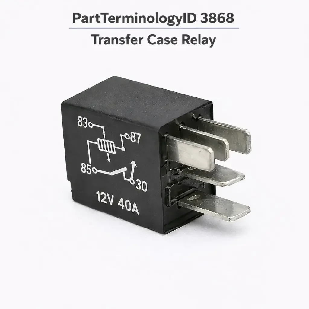
The Transfer Case Relay, cataloged under PartTerminologyID 3868, controls the electrical supply to the transfer case shift motor and determines the direction of that motor's rotation. On electronically shifted transfer case platforms, the shift motor is a bidirectional DC motor that moves the mode fork between 2WD, 4H, and 4L positions by rotating clockwise or counterclockwise depending on which direction the shift is being made. Controlling a bidirectional motor requires two separate relays: one that applies voltage to motor terminal A and grounds terminal B for clockwise rotation, and a second that reverses polarity, applying voltage to terminal B and grounding terminal A, for counterclockwise rotation. These two relays work as a pair. A shift in one direction uses only one relay; a shift in the other direction uses only the other relay. The transfer case control module or generic electronic module commands only the relay appropriate for the requested shift direction and deactivates both relays once the position sensor confirms the shift is complete.
The practical consequence of this paired relay architecture is that the symptom pattern of a relay failure depends entirely on which relay has failed and in which direction. A failed clockwise relay prevents shifts that require clockwise motor rotation, while leaving shifts requiring counterclockwise rotation fully functional. A failed counterclockwise relay does the opposite. On many platforms these two relays are physically identical components in adjacent sockets in a dedicated transfer case relay box, which means they can be swapped with each other for diagnostic purposes to confirm whether the fault follows the relay to its new position.
The relay box location is a significant catalog and diagnostic detail. On Ford ESOF platforms, the relay box is a small dedicated module mounted in the engine compartment near the battery or master cylinder. It has been documented to fall off its mounting bracket and dangle in the engine bay, and when it does, it can fill with water and corrode the relay terminals. A large share of transfer case relay complaints on these platforms are corrosion faults at the relay socket level rather than internal relay failures, and the distinction matters for replacement decisions.
What the Relay Does
Bidirectional Motor Control Through Relay Polarity Reversal
The transfer case shift motor is a permanent magnet DC motor. Like all DC motors, its direction of rotation is determined by the polarity of the supply voltage across its terminals. When terminal A is positive and terminal B is grounded, the motor rotates clockwise. When terminal B is positive and terminal A is grounded, the motor rotates counterclockwise. The two transfer case relays accomplish this polarity reversal by each connecting battery positive to one motor terminal while providing a return ground path through the other.
When neither relay is energized, both motor terminals are de-energized and the motor does not run. The transfer case control module or GEM energizes only one relay at a time during a shift event. Once the encoder position sensor confirms the shift shaft has reached the target position, the module deactivates the relay and the motor stops. The relay is energized only for the brief duration of the shift event, which on most platforms takes two to five seconds. A relay that remains energized after the position sensor has confirmed the completed shift indicates a control module fault rather than a relay fault.
Relationship to the GEM and TCCM
On Ford platforms using the Generic Electronic Module to control the transfer case, the GEM monitors the cab-mounted 4WD selector switch, confirms vehicle speed conditions permit the requested shift, and commands the appropriate relay to run the shift motor. The relay is an output device of the GEM. A fault in the GEM's internal power transistor or relay driver circuit will produce the same symptom as a failed relay: the shift motor does not run in the affected direction. The GEM and the relay are different failure locations with the same symptom presentation, and the relay must be confirmed as the fault location through circuit testing before replacement is appropriate.
On GM platforms using a dedicated Transfer Case Control Module, the TCCM performs the same function with the same circuit architecture: it commands the polarity relay pair to run the shift motor in the appropriate direction. The TCCM's internal relay drivers are a separate fault location from the external relay components in the underhood relay box.
Electromagnetic Clutch Relay
On platforms where the transfer case uses an electromagnetic clutch to spin up the front driveline before engagement when shifting from 2WD to 4H at speed, a separate relay may control the clutch engagement circuit rather than the shift motor direction. This electromagnetic clutch relay is part of the same shift sequence but serves a different load: it energizes the clutch coil inside the transfer case rather than driving the motor. On some applications this relay occupies the same relay box as the motor direction relays. The electromagnetic clutch relay and the motor direction relays are functionally and electrically distinct components. A fault in one does not directly indicate a fault in the others, and replacing all relays together without confirming which has failed generates unnecessary returns.
Top Return Scenarios
Vehicle Stuck in One Drive Mode, Opposite Direction Shift Works Normally
The clearest symptom of a single failed transfer case relay is asymmetric shift behavior: the vehicle shifts normally in one direction but cannot shift in the other. A vehicle that can shift from 2WD to 4H but cannot shift back from 4H to 2WD has a fault in the relay responsible for the motor direction that returns the transfer case to the 2WD position. The reverse pattern points to the other relay.
This symptom is highly specific to the relay pair in the transfer case shift circuit, but it is also produced by a failed motor winding on one polarity, a wiring fault on one of the two motor control lines, or a GEM output driver failure on one channel. The relay swap test, which moves both relays to each other's sockets, is the most efficient first diagnostic step because it requires no tools beyond a relay puller and no measurements. If the failure direction changes with the relay positions, the fault is in a relay. If the failure direction remains the same regardless of relay position, the fault is in the wiring, motor, or control module, not in the relays.
Both Shift Directions Failed, Neither Relay Is Actually Faulty
When neither shift direction works and the vehicle is stuck in its current transfer case position, the most common causes are a blown fuse in the transfer case control circuit, a loss of power to the relay box, a failed ground connection shared by both relays, a failed shift motor, or a failed control module. A relay pair failure in both directions simultaneously from internal relay causes is uncommon. Both relays failing at the same time independently requires both to have developed internal faults at the same time, which is possible but not the dominant cause.
A buyer who replaces both relays because neither shift direction works and finds the symptom unchanged has likely encountered a fuse, power supply, motor, or module fault rather than a relay fault. The relay swap test does not apply to this scenario because there is no functioning shift direction to compare against. Circuit testing with a wiring diagram, confirming fuse integrity, confirming power at the relay box supply terminals, and confirming motor resistance at the motor connector are the required steps before relay replacement in a both-directions-failed complaint.
Relay Box Water Intrusion and Corrosion
The dedicated transfer case relay box on Ford ESOF platforms, positioned near the master cylinder or driver-side battery in the engine compartment, is documented as a water intrusion fault location. The box can accumulate moisture through the relay socket openings, particularly when the mounting bracket becomes loose or broken and allows the box to tilt downward. Corrosion at the relay socket terminals increases resistance in the relay coil circuit, which reduces the current through the coil and prevents reliable relay energization. The relay itself may test correctly when removed and bench-tested, but its coil energization in the vehicle is insufficient because the socket terminals are adding resistance.
A relay that passes a bench coil resistance test but does not energize reliably in-circuit is a socket corrosion fault, not a relay coil fault. The correct repair sequence is to remove the relay, clean the socket terminals, apply dielectric compound, reseat the relay, and retest before ordering a replacement. On platforms where the relay box has been found filled with water or visibly corroded throughout, both relays and the relay box itself should be replaced together, as individual relay replacement into a corroded box will produce early repeat failures on the new relay.
The relay box mounting bracket should be inspected and restored to its correct position whenever the relays are replaced. A relay box that is hanging by its wiring harness will reinstate the water intrusion condition within the next season regardless of how clean the new relays are.
DTC P1820 or P1828 Stored, Relay Ordered Without Circuit Test
Diagnostic trouble codes P1820 through P1828 in the Ford ESOF system indicate faults in specific transfer case circuit elements: P1820 indicates a transfer case shift motor internal fault or open circuit, P1827 indicates a clockwise shift relay coil circuit fault, and P1828 indicates a counterclockwise shift relay coil circuit fault. Code P1827 or P1828 specifically identifies the relay coil circuit as the fault location, which makes relay replacement a more appropriate response than it would be for P1820. However, the relay coil circuit includes the relay coil, the wiring from the GEM output to the relay coil terminal, and the GEM's internal relay driver transistor. The code identifies the circuit, not the specific component.
A relay ordered on the basis of P1827 or P1828 without confirming that the coil circuit fault is located at the relay rather than at the GEM output transistor or the wiring between them has a significant probability of not resolving the fault. GEM output driver failures that set P1827 or P1828 are documented on Ford ESOF platforms. A relay that bench-tests correctly and is installed in a socket that measures correct supply voltage and ground but still does not energize points to a GEM driver fault. The listing must communicate that these codes identify a circuit fault requiring circuit testing before component replacement.
Shift Motor Misidentified as Relay Fault
A failed shift motor produces the same symptom as a failed relay: the transfer case does not shift in the affected direction. Unlike a relay fault, a motor fault typically prevents shifting in both directions unless only one winding of the motor has failed. Confirming motor resistance at the motor connector before replacing the relay prevents the return scenario where the relay arrives, is installed, and the vehicle still does not shift because the motor is the fault.
Motor resistance testing at the motor connector requires disconnecting the motor harness and measuring resistance between the two motor terminals. Normal resistance for most transfer case shift motors is in the range of one to four ohms. An open circuit or a resistance significantly outside this range confirms motor failure. A motor that reads normal resistance but still does not run after the relay is confirmed functioning indicates a motor with an intermittent fault or a control module issue.
Listing Requirements
Every listing for PartTerminologyID 3868 should include:
ACES fitment data confirmed from factory service documentation for platforms with a discrete, externally mounted transfer case relay in the shift motor control circuit; must distinguish applications where the relay is an external socketed component from applications where the relay function is integrated into the transfer case control module or GEM internally
A description of the bidirectional motor control architecture and which relay controls which shift direction, so buyers can identify the specific relay needed based on which shift direction has failed
A note that the relay swap test, exchanging the two relays between their sockets, is the most efficient first diagnostic step for confirming whether the fault is in a relay or in the wiring and motor
A note that DTC P1827 and P1828 identify a relay coil circuit fault but do not confirm the relay as the specific failed component without circuit testing that rules out GEM driver failure
A note that relay box corrosion, particularly on Ford ESOF platforms, is a disproportionate cause of relay complaints; socket inspection and cleaning should precede relay replacement on these applications
A note that a stuck-in-position complaint with no shift in either direction more commonly indicates a fuse, power supply, motor, or module fault than a relay pair failure
Frequently Asked Questions
My truck is stuck in 4H and won't shift back to 2WD. Is the relay the cause?
A fault in the relay responsible for the motor direction that returns the transfer case to 2WD is consistent with this symptom. Perform the relay swap test first: exchange the two relays in the relay box between their sockets and retest both shift directions. If the vehicle can now shift back to 2WD but cannot shift into 4H, the fault moved with the relay and confirms a faulty relay. If the behavior is unchanged, the fault is in the wiring, motor, or control module rather than in the relay.
I have codes P1827 and P1828 stored. Do I need to replace both relays?
P1827 indicates a fault in the clockwise shift relay coil circuit and P1828 in the counterclockwise relay coil circuit. Both codes together suggest either a common fault affecting both circuits, such as a shared wiring fault, a GEM output driver failure, or a relay box power supply loss, rather than two simultaneous independent relay failures. Circuit testing to identify the common fault location should precede component replacement. Replacing both relays into a relay box that has a wiring or power supply fault will not resolve the codes.
My 4WD won't shift in either direction. Should I replace the relay?
A total loss of both shift directions simultaneously is more commonly caused by a blown fuse, a lost power supply to the relay box, a failed motor, or a failed control module than by two simultaneously failed relays. Confirm fuse integrity and confirm power at the relay box supply terminals before ordering relays. If power is present at the box and the motor tests normal resistance at its connector, the control module is the most likely fault.
I replaced the relay and the new one failed within a few weeks. What went wrong?
Early repeat failure of a new relay after short service typically indicates relay socket corrosion on Ford ESOF platforms. A corroded relay socket increases coil circuit resistance, causing the relay coil to draw insufficient current and develop heat that degrades the new relay's coil faster than normal. Clean the relay socket terminals, apply dielectric compound, confirm the relay box mounting bracket is intact and the box is correctly positioned, and inspect for water intrusion signs before installing another relay.
Can I swap the clockwise and counterclockwise relays to test which one has failed?
Yes. On platforms where the two relays are physically identical components in adjacent sockets, exchanging their positions is the standard first diagnostic step. If the failure direction reverses after the swap, the faulty relay has been identified and only that relay needs replacement. If the failure direction does not change, the fault is in the wiring, motor, or control module and relay replacement will not resolve it.
What Sellers Get Wrong
Not distinguishing the relay's shift direction function
The most consequential listing error for this PartTerminologyID is treating the transfer case relay as a single component that either works or does not, without explaining that the relay pair controls motor direction and that one relay controls clockwise rotation while the other controls counterclockwise rotation. A buyer who has identified that their vehicle shifts in one direction but not the other needs the relay that controls the failed direction. A listing that does not make this directional distinction gives the buyer no basis for determining which relay to order, leading to returns from buyers who ordered the wrong relay or who ordered both relays when only one had failed.
Not explaining the relay swap test
The relay swap test is both the most efficient diagnostic confirmation for a suspected relay fault and the most reliable method of avoiding unnecessary relay replacement on wiring and motor faults. A listing that directs buyers to the relay as the first replacement step without mentioning the relay swap test will generate returns from buyers whose fault is in the wiring or motor and whose new relay makes no difference. The swap test costs nothing except the time to pull two relays and reinstall them reversed, and its result is definitive.
Attributing P1827 and P1828 directly to relay failure without GEM caveat
P1827 and P1828 are the most common codes associated with transfer case relay complaints, and they generate a high volume of relay replacement purchases. A significant portion of P1827 and P1828 faults on Ford ESOF platforms are attributable to GEM internal output driver failures rather than to the external relay. A buyer who replaces the relay on the basis of these codes and finds them return immediately after installation has a GEM fault. The listing must include a note that these codes identify the relay coil circuit rather than the relay itself, and that GEM driver testing is required before relay replacement on persistent or immediately recurring code conditions.
Not addressing the relay box mounting and corrosion issue
The relay box mounting bracket failure on Ford ESOF platforms is a documented and widespread cause of relay and relay socket deterioration. A listing that does not mention relay box position inspection and corrosion assessment as part of the relay replacement procedure will generate repeat sales from the same customers, which sounds appealing until those customers associate the repeat failure with the part quality rather than with the installation environment. Including relay box inspection guidance in the listing prevents early repeat failures and supports buyer confidence in the replacement.
Treating both-directions-failed as equivalent to one-direction-failed
The diagnostic approach for a vehicle that cannot shift in either direction is entirely different from a vehicle that can shift in one direction but not the other. The listing should acknowledge both symptom patterns and direct buyers with both-directions-failed symptoms to fuse and power supply confirmation before relay replacement, distinguishing this scenario from the asymmetric failure that most directly indicates a relay fault.
Cross-Sell Logic
Transfer case shift motor (the bidirectional DC motor driven by the relay pair; when the relay is confirmed functioning and the shift still does not occur, the motor resistance and mechanical freedom are the next diagnostic targets; motor failure is the most common non-relay cause of a directional shift failure)
Transfer case control module or GEM (the control module that commands the relay coil circuits; GEM internal driver failures produce the same symptoms as relay failures and share the same diagnostic codes; confirmed when the relay tests good, the wiring tests good, and the code persists)
Transfer case relay box or relay bracket (the mounting hardware for the relay box; on Ford ESOF platforms the relay box mounting bracket is a known failure point; replacing relays without restoring the relay box to its correct mounted position reintroduces the water intrusion condition)
Fuse associated with the transfer case circuit (a blown transfer case circuit fuse is the most common single cause of a both-directions-failed complaint; always confirm fuse integrity before relay replacement on total loss of shift function)
Transfer case encoder position sensor (the position sensor that tells the control module when the shift is complete and signals the relay to deactivate; a failed position sensor can cause the motor to run continuously because the module never receives the completion signal, creating a relay that is energized continuously rather than briefly; a shift motor that runs without stopping after a shift request indicates a position sensor or module fault rather than a relay fault)
Final Take
PartTerminologyID 3868 requires more directional diagnostic precision than most relay listings because the component exists in a matched pair where each relay is responsible for only one of the two possible shift directions. The buyer who identifies the correct relay to replace is the buyer who has already performed the relay swap test and confirmed that the fault follows the relay position. The listing that explains this test converts a diagnostic step into a sales tool: a buyer who performs the swap test and confirms a faulty relay already knows they need exactly one relay and has confidence that the replacement will resolve their symptom.
The GEM driver caveat on P1827 and P1828 is the second critical element. These codes drive a large volume of relay replacement purchases, and a meaningful portion of those purchases on Ford ESOF platforms end with the code returning immediately after relay installation because the GEM's internal output driver has failed. The listing that communicates this possibility before the purchase reduces returns from buyers who would otherwise assume the new relay was defective, and it directs them to the correct next diagnostic step before they return the relay and escalate the complaint.
Disclaimer
This guide is intended for catalog research, parts listing, and diagnostic reference. Transfer case relay circuit architecture, relay box locations, and control module logic vary by manufacturer, model year, and 4WD system type. Always confirm application data against factory wiring diagrams and OEM service documentation before finalizing a listing or parts recommendation. PartsAdvisory and its contributors are not responsible for fitment errors arising from catalog data that has not been independently verified against official OEM sources.