Automatic Transmission Torque Converter Inhibitor Relay (PartTerminologyID 3860): Diagnosis, Return Prevention and Listing Guide
Written by Arthur Simitian | PartsAdvisory
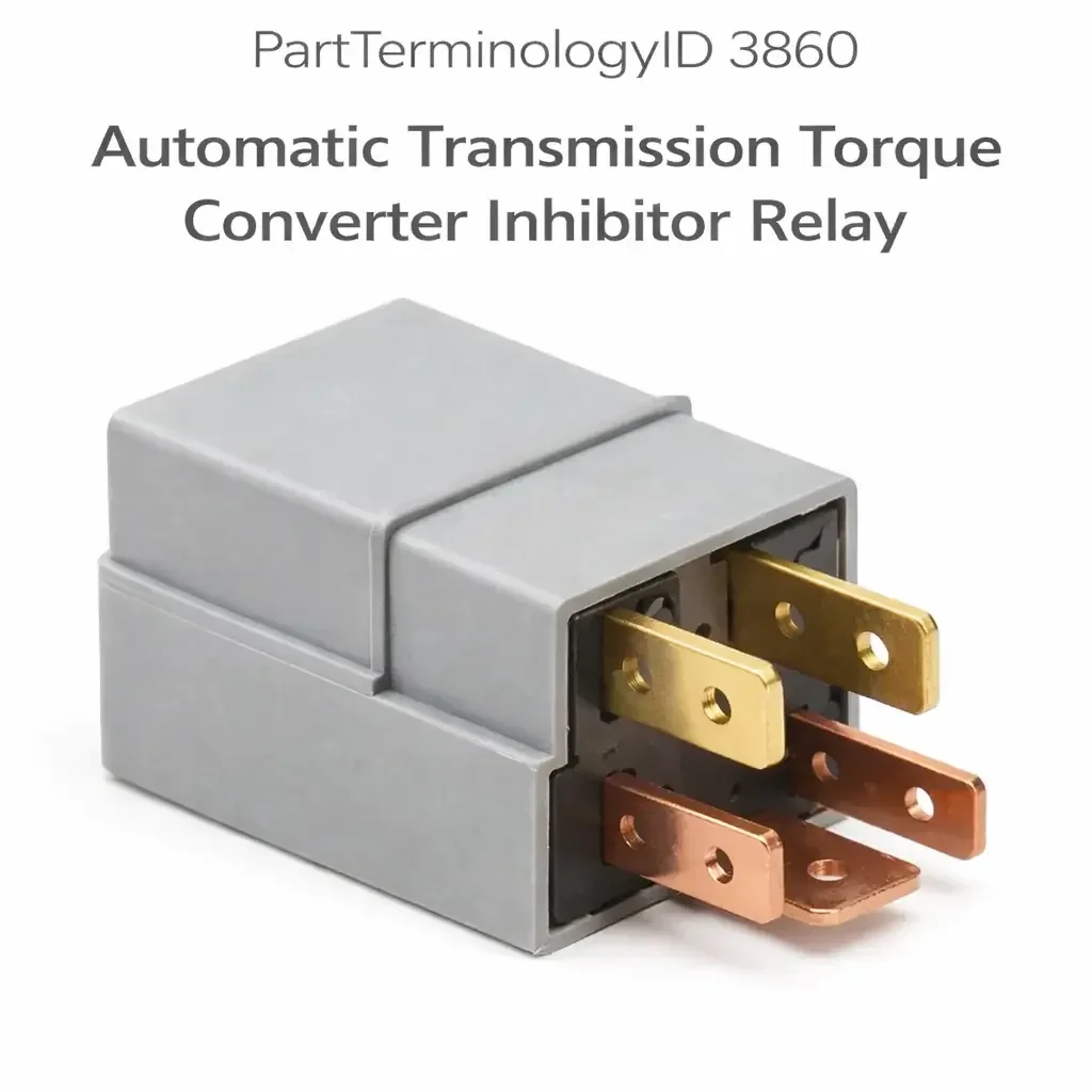
The Automatic Transmission Torque Converter Inhibitor Relay, cataloged under PartTerminologyID 3860, is a relay that prevents the torque converter lockup clutch from engaging under conditions where engagement would cause drivability problems, drivetrain stress, or stalling. It sits in the control circuit between the transmission control module or powertrain control module and the torque converter lockup solenoid, and its function is to interrupt or permit that circuit based on a set of inhibiting conditions. The defining characteristic of this relay is that it blocks lockup rather than enabling it: when the relay is energized or in its default state depending on circuit architecture, it holds the lockup solenoid circuit open and prevents converter lockup from occurring. When the inhibiting conditions clear and the relay releases, the transmission control module is then free to command lockup through the solenoid in the normal way.
The inhibiting conditions it responds to vary by application but typically include cold engine coolant temperature, low vehicle speed, high throttle angle, closed-throttle coast-down in specific drive modes, brake pedal depression, or combinations of these signals. The relay acts as a gatekeeper that enforces these conditions at the hardware level, supplementing or in some applications predating the software logic in the transmission control module. On older automatic transmission platforms from the late 1980s through the mid-2000s, discrete inhibitor relay modules were common because the electronic control sophistication of the transmission controller was limited enough that hardware relay logic was the practical way to implement these protections. On most modern platforms, the inhibitor function has been absorbed entirely into transmission control module software, and no discrete relay component exists in the lockup control circuit.
The distinction between platforms that use this discrete relay and platforms that do not is the most important catalog boundary for PartTerminologyID 3860. An application where the TCM directly controls the lockup solenoid through a software-managed output should not appear in this listing's ACES data. Only platforms confirmed to have a socketed, discrete inhibitor relay module in the lockup clutch supply or control circuit are correct fitment for this PartTerminologyID.
What the Relay Does
Torque Converter Lockup and Why It Must Be Inhibited
The torque converter couples the engine to the automatic transmission through fluid coupling during low-speed and high-load conditions, allowing the engine to operate at a different speed than the transmission input shaft. At cruising speeds under light load, this fluid coupling relationship is mechanically inefficient: the fluid slippage between the pump and turbine generates heat and wastes fuel. The lockup clutch mechanically links the engine and transmission input shaft to eliminate this slippage, improving fuel economy by several percent and reducing torque converter operating temperature under sustained highway load.
The lockup clutch engagement is not appropriate under all operating conditions. Engaging it at low vehicle speed creates a drivability problem similar to engaging the clutch of a manual transmission at too low an RPM: the engine lugs, shudders, or stalls. Engaging it during sudden heavy acceleration from cruise speed causes a momentary hesitation because the transmission cannot provide a fluid torque multiplication response while the converter is locked. Engaging it when the engine coolant is cold causes poor drivability and increased emissions because the engine needs the flexibility of fluid coupling to stabilize during the warm-up period. Engaging it when the brake pedal is depressed can cause stalling in some calibrations. The inhibitor relay enforces the hardware boundaries that prevent lockup engagement under these conditions, regardless of what the transmission control module is commanding.
Circuit Architecture: Normally Open vs. Normally Closed Applications
The relay can be implemented in either of two circuit architectures depending on the application. In a normally-open implementation, the relay contacts are open at rest, and the relay must be energized to close the lockup solenoid circuit and permit engagement. In this architecture, the inhibiting condition energizes the relay to close the circuit and allow lockup, and releasing the relay contact opens the circuit and prevents it. In a normally-closed implementation, the relay contacts are closed at rest, and the relay must be energized to open the contacts and break the lockup circuit when inhibiting conditions are present. The inhibiting signal energizes the relay coil, which opens the output contacts and prevents lockup.
The distinction between these two architectures matters critically for diagnosis. A relay that has failed open-circuit in a normally-open application means lockup can never be commanded: the circuit is permanently broken. The transmission behaves as though the lockup solenoid is disconnected. A relay that has failed open-circuit in a normally-closed application means lockup is permanently blocked: the contacts are stuck in the inhibited position. Both produce a no-lockup condition but for opposite electrical reasons, and the diagnostic test at the relay socket must account for the architecture before a conclusion is reached.
Temperature Inhibit and the Coolant Signal
On applications where the inhibitor relay incorporates coolant temperature as an inhibiting input, the relay receives a signal from the engine coolant temperature sensor or from a separate thermostatic switch and uses that signal to determine whether lockup is permitted. At cold startup, the relay holds the lockup circuit in the inhibited state until a threshold temperature is reached, after which the relay releases and allows the transmission control module to command lockup when the other conditions permit.
If the coolant temperature sensor feeding the inhibitor relay has failed or is producing an incorrect signal, the relay may hold the lockup circuit in the inhibited state permanently, even after the engine reaches full operating temperature. The transmission will function normally in all respects except that the torque converter will never lock up, and fuel economy will be measurably reduced, particularly on highway driving. This fault produces no warning light on many platforms and no stored transmission code, because the transmission itself is receiving its commands and operating correctly. The inhibitor relay is simply preventing the lockup command from reaching the solenoid.
Interaction with the Brake Inhibit Signal
Many applications route the brake pedal switch signal through the inhibitor relay circuit to release lockup whenever the brake is applied. This is a safety and drivability measure: releasing lockup before braking prevents the drivetrain engagement that could contribute to stalling or cause an abrupt engagement sensation when the brake is released. If the brake pedal switch is stuck in the applied position, or if the circuit feeding the brake inhibit input to the relay has a fault, the relay may hold the lockup circuit permanently open as though the brakes are always applied.
A driver who experiences permanent no-lockup behavior and finds no codes stored should have the brake pedal switch confirmed closed in the released position before the relay itself is condemned. A brake pedal switch that is shorted to ground or stuck activated will produce the same relay behavior as a relay whose output contacts are stuck open, because the relay is responding correctly to a permanently active inhibit signal.
Top Return Scenarios
No Torque Converter Lockup at Highway Speed, Poor Fuel Economy
The most direct symptom of a failed inhibitor relay is the absence of torque converter lockup during highway cruising. The driver may notice elevated engine RPM at a given highway speed compared to what they previously experienced, reduced fuel economy, or a slightly higher transmission operating temperature. On vehicles with a tachometer or a digital trip computer displaying instantaneous fuel economy, the lockup event is often visible as a small RPM drop and an improvement in MPG readout that no longer occurs.
This symptom can also be produced by a failed lockup solenoid, a failed torque converter clutch, a failed transmission control module output, contaminated transmission fluid, worn converter clutch friction material, or the inhibitor relay holding the circuit open in response to a fault in one of its input signals rather than a fault in the relay itself. The relay is one node in a circuit that includes all of these components. Replacing the relay without verifying that the relay is the failed node returns the buyer with the same symptom and an intact relay.
Correct diagnosis requires confirming that the lockup solenoid circuit is receiving no activation signal despite the transmission control module commanding lockup. If the TCM is not commanding lockup because it is seeing a fault in one of its inputs, the relay is functioning correctly and replacement accomplishes nothing. If the TCM is commanding lockup and the solenoid activation signal is being blocked at the relay, the relay is the fault.
Torque Converter Lockup at Low Speed, Shudder, or Stall
A relay that has failed with its output contacts stuck closed in a normally-open application, or with its coil failing to energize in a normally-closed application, will allow lockup to occur without any inhibition. The transmission control module can command lockup at any vehicle speed, any coolant temperature, and regardless of brake pedal position. The driver experiences torque converter engagement at low speeds where it should not be happening: a shudder or lurch during city driving, a stall when slowing to a stop if lockup is engaged at very low speed and the engine cannot maintain idle against the driveline load, or an unusual hesitation during heavy-acceleration events from cruise speed.
This is the failure mode most likely to be misdiagnosed as a torque converter clutch problem, a transmission internal fault, or even an engine misfire, because the sensation of lockup engagement at low speed resembles a drivetrain roughness symptom rather than an obviously electrical fault. A relay test at the socket, confirming that the relay is permitting lockup in conditions where it should be inhibiting it, is the diagnostic confirmation.
Permanent No-Lockup After Coolant Temperature Sensor Replacement
A coolant temperature sensor replacement performed without clearing adaptive data from the inhibitor relay circuit, or performed with a sensor that has a different resistance curve from the original, can leave the relay in a state where it interprets the new sensor's signal as indicating a cold engine even after the engine reaches operating temperature. This presents as a no-lockup symptom that appeared immediately after a coolant system service. The buyer replaces the relay expecting to restore lockup, finds that the new relay behaves identically to the old one, and returns the relay. The actual fault is the sensor signal mismatch or a residual offset in the relay's temperature input circuit, not the relay itself.
Any no-lockup complaint that appeared after a coolant system service should include verification that the coolant temperature sensor signal at the inhibitor relay input matches the expected value for a fully warmed engine before relay replacement is considered.
Relay Socket Corrosion Causing Intermittent Inhibit
A relay that tests correctly in bench conditions but produces intermittent no-lockup behavior in the vehicle is often the result of corrosion at the relay socket pins rather than internal relay failure. The socket terminals carry low-current signal inputs from the temperature sensor, brake switch, and vehicle speed circuit alongside the higher-current output to the solenoid supply. Corrosion at any of these contacts increases resistance and can cause voltage drops sufficient to affect relay coil energization or output contact behavior. Cleaning the relay socket contacts and applying dielectric compound to the socket before reseating the original relay resolves intermittent inhibit behavior on a significant share of these complaints without replacing the relay at all.
A buyer who replaces the relay without addressing socket corrosion may find the new relay produces the same intermittent symptom within weeks. The listing should note socket inspection as part of the installation procedure.
Code P0740 or Related Lockup Codes Without Confirming Relay Circuit
Diagnostic trouble code P0740, torque converter clutch circuit malfunction, and related codes such as P0741, P0742, and P0743 indicate a fault detected in the torque converter lockup control circuit. These codes are stored by the transmission control module when the circuit response does not match the commanded state. On platforms that use a discrete inhibitor relay, the relay is one possible location of the circuit fault, but the code does not specify the relay as the failed component. The solenoid itself, the wiring between the relay output and the solenoid, the wiring between the TCM and the relay coil input, and the power supply to the relay are all equally possible fault locations.
A buyer who replaces the relay based on P0740 without performing a wiring diagram-guided circuit test will return the part at a rate consistent with their probability of having guessed the correct fault location among five or more possible fault nodes. The listing must include a note that these codes require circuit testing before component replacement, and that the relay is the correct replacement only when circuit testing confirms the fault is at the relay.
Listing Requirements
Every listing for PartTerminologyID 3860 should include:
ACES fitment data confirmed from factory service documentation for platforms with a confirmed discrete, socketed torque converter lockup inhibitor relay module; must exclude platforms where the inhibitor function is implemented entirely within TCM or PCM software logic with a standard relay or direct solenoid output
A description of the relay's inhibitor function and the conditions it enforces: cold engine protection, low-speed inhibit, brake inhibit, and throttle-angle inhibit as applicable to the specific application
A circuit architecture note identifying whether the application uses a normally-open or normally-closed relay configuration, as this determines the failure mode and diagnostic approach
A note that P0740 and related codes indicate a circuit fault at one of several possible nodes and do not confirm the relay as the failed component without circuit testing
A note that the brake pedal switch and coolant temperature sensor are common upstream causes of a permanent inhibit condition that mimics a failed relay
Socket inspection guidance as part of the installation procedure
Frequently Asked Questions
My transmission never locks up on the highway anymore. The RPM is higher than it used to be. Is the inhibitor relay the cause?
Permanent no-lockup with elevated highway RPM is the most direct symptom associated with this relay's failure in the inhibited position. However, the same symptom is produced by a failed lockup solenoid, a failed torque converter clutch, contaminated transmission fluid, or the relay correctly responding to a fault in one of its input signals. A wiring diagram-guided circuit test confirming that the lockup solenoid is not receiving an activation signal despite the TCM commanding lockup, and that the open circuit is located at the relay rather than at the solenoid or in the wiring, is the correct basis for relay replacement.
I have code P0740 stored. Does that mean I need this relay?
P0740 indicates a fault in the torque converter lockup control circuit. On platforms that include a discrete inhibitor relay, the relay is one possible fault location, but the code does not identify which component in the circuit has failed. Circuit testing using the wiring diagram for the specific application is required to confirm whether the fault is at the relay, the solenoid, a wiring connector, or the TCM output circuit before relay replacement is appropriate.
My car shudders when slowing for a stop. Could the inhibitor relay be causing this?
A relay that has failed in the non-inhibited position, allowing lockup to engage at low speeds where it should be blocked, can produce shudder or a lurching sensation during deceleration and low-speed driving. Testing whether lockup is being commanded and whether the solenoid is being activated during conditions where the inhibitor should be holding the circuit open will confirm or exclude the relay as the cause. Torque converter clutch friction material wear, fluid contamination, and low fluid level produce similar shudder symptoms through different mechanisms and must be evaluated alongside relay function.
The relay I removed and tested with a 12V supply closes its contacts immediately when I apply voltage. Is that normal?
This depends on the circuit architecture of the application. In a normally-open application where the relay energizes to permit lockup, immediate contact closure when the coil is energized is correct behavior. In a normally-closed application where the relay energizes to inhibit lockup, immediate contact opening when the coil is energized is correct behavior. In either case, the relay's resting state with no coil voltage applied is the reference: contacts open at rest in a normally-open relay, contacts closed at rest in a normally-closed relay. Confirming the relay's resting state against the circuit diagram for the application confirms whether it is functioning correctly before any replacement decision.
How do I know if my vehicle uses a discrete inhibitor relay or handles this function in the TCM software?
The factory wiring diagram for the transmission control circuit is the authoritative source. A discrete inhibitor relay will appear as a named relay component in the torque converter lockup control circuit, with identified coil inputs from temperature, speed, and brake circuits and an identified output to the lockup solenoid supply. If the wiring diagram shows the TCM directly driving the lockup solenoid output without an intermediate relay in the control circuit, the inhibitor function is software-integrated and no discrete relay exists. The factory relay box diagram identifying each relay position by part number and function is the secondary confirmation.
What Sellers Get Wrong
Including platforms where the inhibitor function is in TCM software
The most consequential listing error for this PartTerminologyID is extending fitment data to platforms where no discrete inhibitor relay exists because the transmission control module handles all lockup inhibit conditions through software. On these platforms, a buyer who searches for the relay, finds a listing that covers their vehicle, purchases the part, and then cannot find the relay in the vehicle will return the part and lose confidence in the catalog. The fitment data for PartTerminologyID 3860 must be restricted to platforms with a confirmed discrete, socketed relay component in the lockup control circuit, not platforms where the function exists only as TCM logic.
Not identifying the circuit architecture in the product description
A relay that fails open-circuit in a normally-open application produces permanent no-lockup because the circuit is broken. A relay that fails open-circuit in a normally-closed application also produces permanent no-lockup because the contacts are stuck in the inhibited position. The symptom is the same but the relay's normal operating behavior, and therefore the correct diagnostic test, is opposite. A listing that does not identify the circuit architecture forces the buyer to guess whether the relay should have its contacts open or closed at rest, which leads to incorrect bench testing conclusions and returns from buyers who condemned a functioning relay because it did not behave as they expected.
Attributing P0740 directly to this relay without a circuit test caveat
P0740 is one of the most common codes associated with torque converter lockup complaints, and it produces a high volume of relay replacement purchases on platforms that use this relay. The majority of those purchases are made without a circuit test confirming the relay as the fault. The return rate from buyers who find the code persists after relay replacement is directly proportional to how clearly the listing communicates that the code identifies a circuit fault requiring circuit testing, not a specific failed component. A listing that omits this caveat converts code-driven buyers at a high rate but returns them at a nearly equal rate when the underlying fault was in the solenoid, wiring, or TCM output.
Not addressing the brake switch and coolant sensor as upstream fault causes
The two most common upstream causes of a permanent inhibit condition that mimics a failed relay are a brake pedal switch that is shorted or stuck in the applied position and a coolant temperature sensor providing an incorrect cold signal at the relay input. Both causes produce a functioning relay that is correctly blocking lockup in response to a signal that is permanently active when it should not be. A buyer who replaces the relay in either of these conditions installs a new relay that behaves identically to the old one and returns it. The listing must specifically identify these upstream inputs as pre-replacement checks.
Omitting socket inspection guidance
Relay socket corrosion is a disproportionate cause of intermittent inhibitor relay complaints compared to internal relay failure, particularly in older vehicles and in applications where the relay is in an exposed underhood location. A buyer who replaces the relay without cleaning and inspecting the socket contacts will often find the symptom returns within weeks because the new relay is subject to the same contact resistance that caused the original complaint. Including socket inspection and dielectric compound application as installation steps in the listing reduces repeat returns and improves buyer satisfaction with the replacement.
Cross-Sell Logic
Torque converter lockup solenoid (the output load the inhibitor relay controls; when the relay is confirmed functioning and lockup still does not occur, the solenoid itself is the next component in the circuit and the most common non-relay cause of no-lockup complaints)
Coolant temperature sensor (a primary inhibit input for temperature-gated applications; an incorrect cold signal from a failing sensor will hold the relay in the inhibited state permanently even with a fully warmed engine; confirm sensor output before relay replacement on no-lockup complaints on cold or recently serviced cooling systems)
Brake pedal switch (the brake inhibit input to the relay; a switch that is shorted to the applied position or mechanically stuck will hold the lockup circuit permanently open; confirm brake switch operation before relay replacement on permanent no-lockup complaints)
Automatic transmission fluid and filter (contaminated or degraded fluid is an independent cause of torque converter clutch shudder, poor lockup quality, and P0740; fluid condition should be confirmed before electrical diagnosis on lockup complaints to avoid electrical component replacement on a fluid-condition fault)
Torque converter assembly (when the relay and solenoid are confirmed functioning and lockup still does not occur, or when shudder persists after all electrical components are confirmed good, the torque converter's internal clutch friction material and piston are the mechanical fault location)
Vehicle speed sensor (vehicle speed is a common inhibitor relay input on speed-gated applications; a failed VSS producing a zero or erratic speed signal may hold the relay in the low-speed inhibited state even at highway speeds)
Final Take
PartTerminologyID 3860 occupies a narrow but specific position in the automatic transmission relay catalog. Its function is the mirror image of most relays: it exists to block rather than to enable, and its most common failure mode in one circuit architecture produces the same symptom, no lockup, as its most common failure mode in the opposite architecture. A listing that does not account for both architectures and both failure modes will generate diagnostic confusion from buyers who test the relay and find behavior they did not expect.
The most important catalog discipline for this PartTerminologyID is fitment scope. The discrete inhibitor relay is a component from an era of transmission control where hardware relay logic was the practical implementation of protection conditions that modern TCMs handle in software. Extending the fitment data to modern platforms where no such relay exists generates the most damaging return scenario in the catalog: a buyer who searches for a relay that is not in their vehicle, finds it in the listing, buys it, and then cannot locate it anywhere on the car. Platform-by-platform confirmation from factory wiring diagrams is the only reliable basis for this listing's ACES data, and it is the work that separates a catalog that sells this relay well from one that sells it and then takes it back.
Disclaimer
This guide is intended for catalog research, parts listing, and diagnostic reference. Circuit architecture, relay specifications, and control logic vary by manufacturer, model year, and transmission variant. Always confirm application data against factory wiring diagrams and OEM service documentation before finalizing a listing or parts recommendation. PartsAdvisory and its contributors are not responsible for fitment errors arising from catalog data that has not been independently verified against official OEM sources.