Brake Light Fail Relay (PartTerminologyID 3824): Diagnosis, Return Prevention and Listing Guide
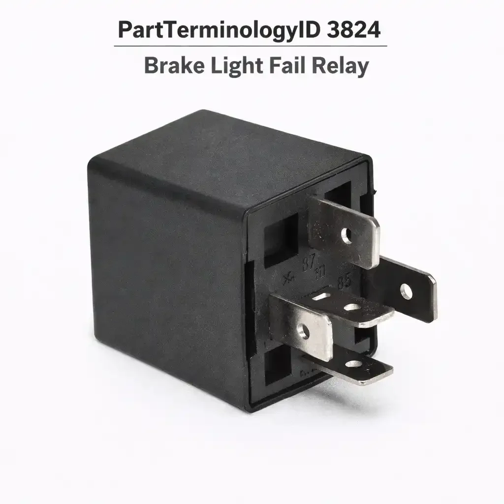
The Brake Light Fail Relay, cataloged under PartTerminologyID 3824, is a relay that performs two functions simultaneously: it is the supply relay that routes brake switch voltage to the stop lamp bulbs, and it is the monitoring component that detects a failed bulb filament and activates the instrument cluster warning lamp when a bulb is out. These two functions are housed in a single electromechanical unit. When the brake pedal is pressed, the relay closes its contacts and delivers supply voltage to the rear stop lamp circuit. At the same time, an internal current-sensing element monitors how much current the bulb circuit is drawing. If all bulbs are intact and drawing their expected load, no warning is generated. If a filament fails and the circuit current drops below the expected threshold, the relay triggers the dashboard bulb failure indicator, alerting the driver to a brake lamp that is out before the problem becomes a hazard or a traffic stop.
This design is predominantly found on European vehicles, with Volvo 700, 900, 850, V70, and S70 series being the clearest and most widely documented application. Volvo built brake light failure detection into the circuit architecture for decades, and the component responsible for that detection on these platforms is this relay, known in the Volvo community as the bulb-out relay or lamp failure relay. On some 700 and 900 series applications the relay is visually distinctive: round, red, and clipped to the relay plate in the driver's side footwell area. Because every brake lamp activation passes current through the relay's sensing element, the relay is subject to mechanical and thermal stress with every stop event, and contact failure is common enough that Volvo dealers historically kept them in regular stock and service technicians familiar with these platforms learned to check this relay before replacing bulbs or chasing wiring faults.
What the Relay Does
Current-Sensing Architecture
The brake light supply circuit on platforms using this relay runs through the relay's contacts rather than directly from the brake switch to the bulbs. The relay coil is activated by the brake switch signal, the contacts close, and current flows from the battery through the relay's contact set to the brake lamp bulbs. Inside the relay, a shunt resistor or current-sensing element is wired in series with the lamp supply path. The current flowing through this element represents the total draw of all connected brake lamp bulbs. When all bulbs are present and functioning, the measured current is within a calibrated range and no warning is generated. When a filament fails, the total current drops and the sensing element output falls below threshold, causing the relay to activate the warning lamp output.
On later Volvo platforms using a Rear Electronics Module or Central Locking Module, this function is integrated into the module rather than a discrete relay. A buyer on a platform with an integrated module has no discrete Brake Light Fail Relay to replace regardless of the brake lamp warning status. The fitment data for this PartTerminologyID must be built from confirmation that the platform uses a discrete external relay unit rather than a module with an integrated monitoring function. Ordering a discrete relay for a module-based platform produces an order with no application.
What Happens When the Relay Fails
Because the relay is both the supply component and the monitoring component, relay failure affects both functions simultaneously. When the relay's contact set fails open, the brake lights extinguish completely because the supply path through the relay is broken. The warning lamp behavior when the relay fails open varies by platform: on some applications the warning lamp illuminates because the relay's monitoring output reads zero current, which it correctly interprets as all bulbs out; on others the warning circuit itself loses its reference supply through the failed relay and the warning lamp remains off or behaves erratically.
When the relay's contact set fails closed due to contact welding, the brake lights stay on continuously regardless of pedal position. The sensing circuit may or may not continue to function correctly in this state. Contact welding in a brake light fail relay is less common than open failure but produces an unambiguous symptom that distinguishes it from bulb failure and switch failure.
When the relay's internal sensing element degrades rather than the contact set, the relay continues to supply the brake lights correctly but generates false bulb failure warnings. This mode is responsible for the well-documented pattern on Volvo platforms where the bulb failure indicator illuminates on every brake application despite all bulbs being intact and the circuit having no detectable fault. The sensing element's calibration drifts over time, typically toward false-positive detection, and the only repair is relay replacement.
The Third Brake Light Separation
On Volvo 850, V70, and related platforms, the center high-mount stop lamp is typically on a separate circuit from the two main rear brake lamps that the Brake Light Fail Relay monitors. A buyer who presents with both main rear brake lights inoperative while the CHMSL continues to function normally has useful diagnostic information: because the brake switch feeds all three positions, and the CHMSL is still working, the brake switch is confirmed functional. The fault is in the relay or in the wiring downstream of the relay to the two main lamp positions. This combination of symptoms, two main brake lights out with CHMSL still operational, points directly at the Brake Light Fail Relay and justifies relay replacement before further wiring diagnosis.
Top Return Scenarios
Burned Bulb Filament Triggering the Warning, Not the Relay
The brake light fail warning lamp is doing its job when a filament fails: it is detecting reduced circuit current and informing the driver. A buyer who sees the warning, assumes the relay has malfunctioned, and orders a replacement relay returns it when installing the new relay produces the same warning because the burned bulb was never replaced. The relay in this scenario is working correctly. The diagnosis is to inspect all three brake lamp positions with the ignition on and brake pedal pressed before concluding the relay is at fault. A single failed filament explains the warning completely.
This is the highest-volume return scenario for this PartTerminologyID. The relay's job is to produce a warning when a bulb fails, and many buyers interpret the warning as a relay fault rather than the expected outcome of a successful detection event.
Corroded Bulb Socket Producing a False Positive Warning
Corrosion in a brake lamp socket raises the circuit resistance at that position, reducing the total current draw below the relay's expected threshold even when the bulb filament is intact. The relay detects the current shortfall and activates the warning lamp exactly as designed. The symptom is a brake light failure warning with all bulbs visually intact and illuminating when tested directly. The distinction between a burned filament and a corroded socket is that a corroded socket produces visible light but at reduced brightness, while a burned filament produces no light at all.
The corroded socket does not call for a relay replacement. Cleaning or replacing the socket restores the expected current draw and the warning extinguishes. Buyers who replace the relay without addressing the socket return the relay when the warning returns immediately, because the underlying circuit fault was never corrected.
LED Bulb Conversion Producing Continuous False Warning
The Brake Light Fail Relay's sensing element is calibrated for the current draw of incandescent brake lamp bulbs. LED replacement bulbs draw substantially less current than the incandescent bulbs the relay was designed to monitor, so the relay continuously reads the LED load as a bulb-out condition and keeps the warning lamp illuminated even when all LED bulbs are fully functional. This is not a relay fault. The relay is correctly detecting that the circuit current is lower than the expected incandescent load; it simply cannot know the difference between a failed incandescent and a functioning LED.
The resolution for LED conversion on platforms with a Brake Light Fail Relay is either to retain incandescent bulbs in the monitored positions, to install load resistors in parallel with the LED bulbs to restore the expected current draw, or to investigate whether a relay with a different sensing threshold is available for the specific platform. Ordering a new relay to resolve an LED false-positive warning produces no improvement and generates a return.
Relay Failure Misdiagnosed as Brake Switch Failure
When the Brake Light Fail Relay fails open and extinguishes both main brake lights, the symptom is indistinguishable from a brake switch failure through casual observation: the driver presses the pedal and sees no brake lights in the rear. However, the two-function nature of this relay provides a useful cross-check. If the CHMSL continues to illuminate when the brake pedal is pressed, the brake switch is confirmed functional because it supplies the CHMSL circuit. Brake switch failure would extinguish all three positions including the CHMSL. Both main rear brake lights out with CHMSL still working means the brake switch is fine and the relay is the fault.
Buyers who do not know about this distinction replace the brake switch, find no improvement, and then need to trace the fault further. Listing content that explains the CHMSL separation and its diagnostic significance saves buyers the cost of a brake switch they did not need.
Intermittent Warning from Relay Contact Resistance
Intermittent brake light failure warnings that appear and disappear across multiple drive cycles, where the brake lights appear to function correctly when the warning is absent, are often caused by internal relay contact resistance that has increased as the contacts age and oxidize. High contact resistance in the sensing circuit changes the current measurement slightly, producing intermittent threshold crossings that trigger the warning. Buyers who observe this symptom and attempt to confirm a fault by testing the brake lights while the warning is absent will find no fault and may conclude the relay is fine. The pattern of intermittent warning with no verifiable lamp failure is the primary symptom of a relay with degraded internal sensing contacts, and relay replacement is the correct repair.
Listing Requirements
Every listing for PartTerminologyID 3824 should include:
ACES fitment data confirmed for platforms with a discrete external Brake Light Fail Relay, explicitly separated from platforms that use an integrated Rear Electronics Module or lamp control module with no discrete replaceable relay
A description of the relay's dual function as both supply switch and current-sensing monitor, making clear that the relay failure affects both functions simultaneously
A note that the brake light failure warning lamp indicates a burned bulb in the large majority of cases, and bulb and socket inspection must precede relay diagnosis
A note on LED conversion incompatibility with the current-sensing threshold calibrated for incandescent loads
A note on the CHMSL separation test as the diagnostic step that distinguishes relay failure from brake switch failure on applicable platforms
Frequently Asked Questions
My brake light failure warning lamp came on. Is this the relay?
In most cases, the brake light failure warning lamp indicates a burned brake lamp bulb rather than a relay fault. The relay is functioning correctly when it illuminates the warning in response to a bulb failure. Before considering the relay, press the brake pedal and have someone inspect all three brake lamp positions from outside the vehicle. A dark lamp position confirms a bulb or socket fault at that location. Replacing the failed bulb should extinguish the warning. If all lamp positions illuminate normally and the warning persists, the relay's sensing element may have drifted, producing a false positive, or a corroded socket is producing reduced current draw below the relay threshold without producing complete lamp failure.
Both my main rear brake lights are out but my center high-mount brake light still works. Is this the relay?
Yes, this symptom pattern points directly at the Brake Light Fail Relay on platforms where the CHMSL is on a separate circuit from the two main brake lamp positions. The brake switch is confirmed working because it is successfully activating the CHMSL. The main rear lamp circuit runs through the relay, and both positions losing supply simultaneously while the CHMSL remains functional means the relay's contact set has failed open. Relay replacement restores the main rear brake lamps. If replacing the relay does not restore both main positions, the fault is in the wiring between the relay output and the lamp sockets.
I installed LED brake light bulbs and now the warning lamp is on constantly even though the LEDs work fine. Is this the relay?
This is not a relay fault. The relay's current-sensing element is calibrated for the current draw of incandescent brake lamp bulbs. LED bulbs draw far less current, and the relay reads the reduced LED load as a bulb failure condition because it cannot distinguish between a failed incandescent and a functioning LED drawing low current. The relay is operating correctly. The solution is to install load resistors in parallel with the LED bulbs to restore the current draw that the relay expects, or to return to incandescent bulbs in the monitored positions. Replacing the relay will not resolve LED false-positive warnings.
How do I confirm the relay is faulty rather than a bulb or socket?
The test sequence is: first, verify all bulb filaments are intact by visual inspection or continuity test. Second, verify socket condition by inspecting for corrosion at the contact surfaces. Third, with the brake pedal depressed, probe the relay output terminal to confirm whether supply voltage is present at the relay output side: if input voltage reaches the relay coil and contact terminal but no output voltage appears on the load side, the relay contacts have failed open. On Volvo applications, swapping the suspect relay with an identically formatted relay from another position on the relay plate is a valid swap test if an equivalent unused relay is available. Restoring brake light function through the swap confirms the original relay was the fault.
What Sellers Get Wrong
Not explaining that the warning lamp is the relay working, not failing
The warning lamp this relay generates is evidence of successful detection, not relay failure. A listing that describes the brake light failure warning as a symptom of a bad relay will send buyers who have burned bulbs toward a relay purchase and return. The correct framing is: the warning lamp means the relay detected a fault in the circuit; check the bulb first; the relay is only the candidate if the bulbs and sockets are confirmed good and the warning persists, or if the brake lights themselves are out.
Not addressing LED incompatibility explicitly
LED conversion is one of the most common modifications performed on the Volvo platforms where this relay is used. Buyers who convert to LED and then see the brake light failure warning active at all times are a predictable, high-volume audience for this PartTerminologyID. A listing that does not explain the LED current mismatch will receive returns from every buyer in that group, because a new relay does not resolve a current threshold mismatch. The LED incompatibility note needs to be prominent.
Not distinguishing discrete relay from module-integrated function
Later Volvo platforms and most other modern European platforms moved the lamp monitoring function inside the Rear Electronics Module or equivalent body control module. On these platforms there is no discrete Brake Light Fail Relay to replace, and a buyer who orders one has no location to install it. Application data built without confirming that the platform uses a discrete external relay rather than a module with an integrated monitoring driver will generate a recurring category of orders with no valid application.
Not using the CHMSL separation test as a selling diagnostic tool
The observation that both main brake lights are out while the CHMSL remains active is the clearest single data point that distinguishes relay failure from brake switch failure on applicable Volvo platforms. Listing content that teaches buyers this test converts buyers who would otherwise replace the brake switch first and call back after finding no improvement into buyers who order the correct relay on the first attempt.
Cross-Sell Logic
Brake lamp bulb, applicable stop lamp wattage (the most common cause of brake light failure warnings on platforms with this relay; the relay's job is to detect this failure, and the bulb is the correct first replacement in almost every warning-lamp complaint)
Brake lamp socket or pigtail (corroded sockets raise circuit resistance and trigger false-positive failure warnings with intact bulbs; socket replacement or cleaning resolves persistent warnings that remain after bulb replacement)
Load resistors for LED conversion (required when LED brake lamp bulbs are installed on platforms with a current-sensing relay; restores expected current draw without requiring return to incandescent bulbs)
Brake light switch (secondary candidate when all three brake light positions including CHMSL are dark; the CHMSL continuing to work eliminates the switch and identifies the relay, but if CHMSL is also dark, the switch becomes the primary suspect)
Rear Electronics Module or lamp control module (on later platforms where brake lamp monitoring is integrated into the module rather than a discrete relay; when the discrete relay is not available for the platform, the module is the relevant replacement unit)
Bulb socket repair kit or rear lamp harness repair section (on Volvo applications, melted or heat-damaged bulb sockets in the rear lamp housing are a documented failure mode that produces intermittent failure warnings and can damage replacement relays if not addressed before relay installation)
Final Take
PartTerminologyID 3824 is one of the more educationally demanding relay categories in the aftermarket because the relay's warning output is consistently misread as a relay malfunction. The warning lamp is the relay's intended output when it detects a bulb failure; it is the relay working correctly. Listing content that does not establish this distinction clearly will produce a reliable stream of returns from buyers with burned bulbs who replaced the relay instead.
When the relay is genuinely at fault, the symptom pattern is specific: two main brake lights dark while the CHMSL remains functional, or a persistent failure warning that survives bulb and socket inspection and cannot be attributed to LED conversion. Buyers who arrive with that specific pattern have a confirmed relay fault, and the listing that guided them to that conclusion through triage content earns the sale and retains it.