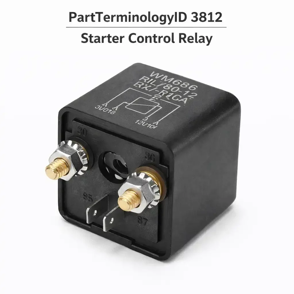
Starter Control Relay (PartTerminologyID 3812): Diagnosis, Return Prevention and Listing Guide
The Starter Control Relay, cataloged under PartTerminologyID 3812, is the relay whose coil circuit is commanded by the powertrain control module, engine control module, or body control module rather than by the ignition switch acting alone. When the driver turns the key to Start or presses the Start button, the ignition switch sends a discrete signal to the BCM or ECM notifying it that a crank has been requested. The control module then verifies that all required conditions are met: the transmission is confirmed in Park or Neutral by the range sensor, or the clutch pedal is confirmed depressed by the clutch switch, and any active inhibit conditions from the security or throttle control systems have been cleared. If all conditions pass, the module supplies voltage or a switched ground to the relay coil, the relay closes, and battery voltage reaches the starter solenoid. If any condition is not met, the module does not command the relay, and the engine does not crank regardless of how the key is positioned.
This architecture distinguishes the Starter Control Relay from the Starter Relay cataloged under PartTerminologyID 3804, which receives its coil trigger directly from the ignition switch without module arbitration. The practical consequence of that distinction is diagnostic: a no-crank on a Starter Control Relay platform cannot be diagnosed by working the ignition switch circuit alone. The diagnostic chain must extend through the control module, its inputs from the range sensor or clutch switch, and its output driver for the relay coil before any relay replacement is justified. The Starter Control Relay is also the relay associated with diagnostic trouble codes P0615, P0616, and P0617, which the PCM sets when it detects an unexpected voltage condition in the relay control circuit. No equivalent DTC exists for the standard Starter Relay because the standard relay's coil circuit is not monitored by any module.
What the Relay Does
The PCM as the Gatekeeper
On platforms that use a Starter Control Relay, the powertrain or body control module sits between the driver's crank request and the relay coil. The circuit architecture typically follows one of two patterns depending on the platform. In one pattern, the ignition switch provides battery voltage to the relay coil's supply terminal, and the PCM or BCM provides a switched ground to the coil's ground terminal to complete the circuit and energize the relay. In the other pattern, the module supplies the voltage to the coil directly. In either case, the module's participation is mandatory and monitored. The module supplies the coil trigger only after verifying the range sensor or clutch switch input, confirming the absence of active inhibit conditions, and determining that the start request is legitimate. The relay is the hardware output of that determination.
The significance of this architecture is that the module can set a DTC if the relay circuit behaves unexpectedly. P0615 indicates a general malfunction in the starter relay control circuit detected by the PCM. P0616 indicates that the circuit voltage is lower than expected when the relay should be energized. P0617 indicates that circuit voltage is higher than expected when the relay should be de-energized, which can indicate welded relay contacts or a wiring short that is holding the circuit active. Any of these codes present alongside a no-crank condition makes the Starter Control Relay and its circuit the primary diagnostic target, but the code alone does not confirm relay failure. The control circuit includes the relay, its socket, the wiring between the relay and the PCM output pin, and the PCM output driver itself, any of which can produce the same code.
Inhibit Conditions That Prevent Relay Command
The Starter Control Relay platform's no-crank diagnostic must include evaluation of every module input that gates the relay command. On automatic transmission platforms, the transmission range sensor or neutral safety switch must confirm Park or Neutral before the PCM will command the relay. A faulty, misadjusted, or damaged range sensor produces the same external no-crank symptom as a failed relay. The test is identical to the manual transmission clutch switch test: shift the selector to different positions while holding the key in Start and note whether any position produces cranking.
On manual transmission platforms, the clutch pedal switch must confirm full pedal depression. A failed switch, a worn plunger bumper, or a connector issue at the switch prevents the PCM from seeing the required input and the relay is never commanded. On platforms with an active security system, an unauthorized key or a failed transponder receiver can send an inhibit signal to the PCM that prevents the crank command from being issued. On platforms with electronic throttle control, some PCM calibrations include an ETC inhibit that prevents cranking if the throttle control system has flagged a fault. The relevant scan data PIDs for each of these inputs must be checked before the relay is declared the fault.
Module Output Driver Failure
The PCM or BCM output driver that supplies the relay coil trigger is an internal transistor. If this transistor fails, the coil receives no trigger and the relay does not close. A failed output driver produces the same no-crank symptom as a failed relay or a faulty range sensor, but the driver failure is inside the module and is not corrected by replacing the relay. The output driver failure is confirmed by back-probing the relay coil terminal that connects to the PCM output pin: if no voltage or ground signal appears at that terminal during a start attempt despite correct power supply and coil ground on the other terminal, and the relay and wiring have been verified good, the output driver is the fault. Module output driver failures are uncommon but are more likely on platforms with known PCM corrosion or moisture intrusion issues.
Platform Architecture: Relay Present vs. No External Relay
Not every modern platform with module-mediated starting uses a discrete external Starter Control Relay. Some platforms, including those using the Totally Integrated Power Module or similar integrated fuse and relay architectures, implement the starter control function entirely within the TIPM or equivalent integrated module. There is no external relay to pull or replace. The fuse block position labeled STRTR or STARTER on these platforms may be occupied by an internal switching component, not a removable relay. Ordering a Starter Control Relay for one of these platforms generates a part that has no socket to plug into.
The ACES fitment data for this PartTerminologyID must be built from factory service manual confirmation that the platform uses a discrete external Starter Control Relay in an accessible fuse block position. Platforms that implement starter control internally within an integrated power module have no application for this relay.
Top Return Scenarios
PCM Not Commanding the Relay Due to Range Sensor or Clutch Switch Fault
The most common return scenario for this PartTerminologyID is a buyer whose park/neutral switch or clutch pedal switch has failed and who orders a new Starter Control Relay before connecting a scan tool. The buyer installs the relay, finds the no-crank unchanged, and returns it. The relay was never the fault: the PCM was not sending the coil trigger because it was not receiving the range sensor or clutch switch input it required. Confirming this before ordering requires only a scan tool capable of reading the relevant input PIDs. Park/Neutral switch status and clutch switch status are visible in live data on virtually every platform that uses a PCM-commanded starter circuit. A switch showing incorrect status is the fault; the relay is not implicated.
Relay Ordered Based on P0615 Without Further Diagnosis
P0615 is stored in the PCM when the starter relay control circuit exhibits an unexpected voltage condition. It is commonly retrieved from a no-crank vehicle and commonly interpreted as confirmation that the relay is bad. A relay that tests fine by swap or bench test, installed in a circuit where the PCM output driver is not supplying the coil trigger, will not crank the engine and will be returned. The P0615 code confirms that the PCM has detected a fault in the circuit. It does not confirm that the relay is the faulty component within that circuit. Correct diagnosis follows the code with voltage testing at the relay socket: power on the supply terminal, PCM trigger signal on the coil terminal, and continuity from the load terminal to the starter solenoid. If the PCM trigger signal is absent with the key in Start, the wiring between the PCM and relay socket or the PCM output driver is the fault.
Platform Uses Integrated Module, No External Relay Present
A buyer on a platform with an integrated power module finds a STRTR or STARTER labeled position in the fuse box, interprets it as a relay socket, and orders a Starter Control Relay. On platforms where starter control is handled internally within the TIPM or equivalent module, that position is not an accessible relay socket. The relay has no home to be installed in, and the buyer returns it. This scenario is concentrated on Chrysler/FCA products from the mid-2000s onward that use the TIPM architecture, but equivalent integrated platforms exist from GM, Ford, and others. Listing content must explicitly address this distinction and direct buyers to verify relay accessibility before ordering.
Welded Relay Contacts Causing Continuous Cranking
A Starter Control Relay whose contacts have welded in the closed position causes the starter to engage every time the key is in the run position, or to continue cranking after the engine starts. This is a genuine relay failure that is addressed by replacing the relay, and P0617 may be stored. However, this failure mode is frequently misinterpreted: a buyer experiencing intermittent post-start cranking engagement attributes it to the relay, replaces it, and finds the behavior unchanged because the actual fault is a shorted wire between the relay load terminal and the starter solenoid that is bypassing the relay entirely. Confirming welded contacts requires removing the relay from its socket and verifying that the starter no longer engages. If the starter continues to engage with the relay removed, the wiring is shorted, not the relay.
Ignition Switch Fault Misidentified as Relay Fault
On some platforms, the ignition switch supplies the voltage to the relay coil's battery-side terminal, and the PCM provides the switched ground. A failed ignition switch contact at the Start position means that no voltage arrives at the relay coil terminal regardless of whether the PCM is commanding the ground. The result is a no-crank with a PCM that may show the crank request as active in live data but cannot close the relay because the coil has no supply voltage. The buyer sees a PCM that appears to be commanding a crank, orders the relay, finds no change. The ignition switch is the fault. Voltage testing at the relay supply terminal during a start attempt confirms or eliminates this scenario in one measurement.
Listing Requirements
Every listing for PartTerminologyID 3812 should include:
ACES fitment data built from factory service manual confirmation of discrete external relay presence, with explicit exclusion of platforms that implement starter control within an integrated power module
A clear explanation that the relay coil is commanded by the PCM or BCM, and that a no-crank on these platforms requires scan tool evaluation of module inputs and outputs before relay replacement is justified
A description of the P0615, P0616, and P0617 diagnostic trouble codes as the circuit-level fault indicators associated with this relay, with a note that the code identifies the circuit rather than the relay component
A note that the transmission range sensor or neutral safety switch, and the clutch pedal switch on manual transmission vehicles, must be confirmed functional before the relay is ordered
A note addressing integrated power module platforms where no external relay is present
Frequently Asked Questions
I have a P0615 code and the car won't crank. Does this mean I need a new Starter Control Relay?
P0615 means the PCM has detected a problem in the starter relay control circuit. The relay is one possible fault within that circuit, but the code alone does not confirm which component is at fault. The correct diagnostic sequence starts with a scan tool: check live data for the park/neutral switch or clutch switch status to confirm the PCM is seeing its required inputs, then check whether the PCM is actively attempting to command the relay coil. If the PCM is commanding the relay but the relay is not closing, the relay, its socket, or the wiring between the socket and the PCM output pin are the candidates. If the PCM is not commanding the relay because it is not seeing the range sensor or clutch switch input, those components are the fault and replacing the relay accomplishes nothing.
The car cranks sometimes but not other times. Could this be the Starter Control Relay?
Intermittent no-crank on a Starter Control Relay platform can be the relay, but intermittent range sensor or clutch switch faults are at least as common and are often the actual cause. An intermittent clutch switch that sometimes does not register full pedal depression, or a range sensor whose Park or Neutral position contact is worn, produces exactly this symptom. A scan tool with live data is the correct first step. Watch the range sensor or clutch switch PID while the symptom is active and compare it to when starting is successful. If the switch PID is the variable that changes between successful and failed start attempts, the switch is the fault. If the switch PID is consistent and the relay coil voltage or ground is the variable, the relay or its circuit is the fault.
My fuse box has a slot labeled STRTR but I can't find a relay in it. Is the Starter Control Relay missing from my car?
On platforms with integrated power modules, particularly many Chrysler and FCA products, the STRTR position in the underhood fuse box label guide does not correspond to an accessible relay socket. The starter control function is handled internally within the integrated module and there is no discrete relay to install or remove. If your vehicle's service manual does not show a removable relay in the STRTR position, no external Starter Control Relay is present or needed. Diagnosis and replacement of a starter control fault on these platforms requires addressing the integrated module itself.
Can I just swap the Starter Control Relay with another relay from the fuse box to test it?
The relay swap test is valid as a quick confirmation step but it must be performed after all upstream module inputs have been confirmed. If the PCM is not commanding the relay because of a range sensor fault, swapping the relay produces no change regardless of whether the original relay is good or bad. Confirm range sensor or clutch switch status first, then confirm that the PCM is producing the coil trigger voltage or ground during a start attempt, and then swap the relay if both upstream conditions are confirmed normal. A matched relay from another position in the fuse block can be used. If swapping in a known-good relay restores cranking, the original relay is confirmed faulty.
What Sellers Get Wrong
Treating P0615 as a confirmed relay diagnosis
P0615 is a circuit-level code. It identifies the starter relay control circuit as the location of the fault. It does not identify the relay as the specific faulty component within that circuit. A listing that describes P0615 as meaning the relay is bad will attract orders from buyers whose fault is a PCM output driver failure, a wiring open between the relay socket and the PCM, a corroded relay socket terminal, or a failed ignition switch that is not supplying coil voltage. These buyers install the relay, find no improvement, and return it. The listing must describe P0615 as pointing to the circuit and direct buyers through the upstream voltage tests before ordering.
Not distinguishing this relay from PartTerminologyID 3804
The Starter Relay (3804) and the Starter Control Relay (3812) produce the same external symptom when they fail and overlap in format and physical appearance. The critical difference is the trigger source: 3804 is triggered by the ignition switch directly, and 3812 is triggered by a PCM or BCM output. A buyer who looks up a no-crank on a platform that uses 3812 and finds a generic starter relay article will follow the wrong diagnostic path: they will check the ignition switch circuit, find voltage on the switch output, assume the relay is bad, and order a replacement. If the relay socket's PCM trigger terminal never had a PCM output to begin with, due to a range sensor fault or PCM inhibit, the replacement relay produces no improvement. The listing must make the PCM command architecture visible and central.
Not addressing integrated power module platforms
The distinction between platforms with a discrete external Starter Control Relay and platforms that handle the function internally within an integrated module is the most consequential fitment error for this PartTerminologyID. A buyer on an integrated-module platform who orders a discrete relay has no place to install it. The listing must address this directly and must include a recommendation to verify relay socket accessibility before ordering, particularly for Chrysler/FCA products and any other platform where integrated power modules are common.
Missing the range sensor and clutch switch as primary diagnostic targets
On Starter Control Relay platforms, the range sensor and clutch switch are in series with the relay command path from a diagnostic standpoint. They must be confirmed before the relay is addressed. A listing that mentions only the relay and the PCM as diagnostic candidates, without addressing the range sensor and clutch switch, leaves buyers without the most actionable diagnostic step. These switch inputs are visible in scan tool live data without any wiring access, making them the fastest and least invasive checkpoints in the entire diagnostic sequence.
Cross-Sell Logic
Transmission range sensor or neutral safety switch (the input the PCM requires to confirm Park or Neutral before it will command the relay coil; a failed or misadjusted range sensor is the most common cause of no-crank on automatic transmission platforms equipped with this relay architecture)
Clutch pedal switch on manual transmission applications (the equivalent input on manual transmission platforms; a failed switch prevents the PCM from seeing the required clutch depression confirmation)
Ignition switch (on platforms where the ignition switch supplies the relay coil's battery-side voltage, a failed switch contact at the Start position prevents the relay from closing even when the PCM is attempting to command it)
Starter motor or starter solenoid (downstream of the relay; when the relay is confirmed functional and the solenoid control circuit is confirmed receiving voltage, the solenoid and starter motor are the next diagnostic candidates)
Starter relay, PartTerminologyID 3804 (the functionally adjacent terminology; on platforms where the starting system includes both a PCM-commanded control relay and a downstream relay switched by the solenoid circuit, both are potential fault candidates in a no-crank sequence)
Battery and battery cables (a battery below cranking voltage or a high-resistance cable connection can cause voltage sag on the PCM supply that prevents the output driver from commanding the relay reliably; battery confirmation is the first step on any no-crank regardless of relay type)
Final Take
PartTerminologyID 3812 is the starting-circuit relay that most benefits from a scan tool being in the technician's hands before any part is ordered. The defining characteristic of this relay is that it cannot be evaluated in isolation: the PCM must be confirmed to be commanding it, and the inputs the PCM requires to issue that command must be confirmed present, before the relay itself is a meaningful diagnostic target. A buyer who arrives at this relay with a P0615 code and no scan tool data has confirmed only that the circuit has a problem, not that the relay is the problem.
The return rate for this PartTerminologyID is driven almost entirely by orders placed before upstream conditions were confirmed. The listing that changes that outcome is the listing that makes the scan tool a visible prerequisite, names the range sensor and clutch switch as the most common non-relay faults on these platforms, and addresses the integrated module architecture that eliminates the external relay entirely on a meaningful fraction of the platforms that use PCM-commanded starting circuits.